
Abstract
Explosive welding technology has been widely used in industrial production. However, there is always a controversy on the mechanism of explosive bonding, whether explosive welding should belong to a kind of mature welding such as a fusion welding or a solid phase welding. Based on the observation and analysis of the metallographs at interfaces, various opinions are proposed by different authors. This paper investigated the various mechanisms of the wavy interface formation in explosive welding and tried to determine a more reasonable one by using smoothed particle hydrodynamics method. The numerical analysis results show that explosive welding is a unique and complex kind of welding. In general cases, high pressure and melted particles can be found in the collision area at the interface. A version, in which explosive welding is a combination of diffusion bonding, fusion bonding and pressure welding, is considered as a more reasonable one.
Introduction
Explosive welding is well known on producing similar or dissimilar metal combinations. The main application is to flat plate cladding and the welding of cylindrical surfaces such as tube to tube and tube to tube plate welding.1 During the production process of flat plate cladding, the set-up shown in Fig. 1a is commonly applied. Analysis of the bonding process is conveniently divided into two parts. The first considers the transfer of energy from the explosive, upon detonation, to the flyer plate. A second general consideration is the transformation of flyer plate kinetic energy into deformations at the interface and the actual bonding mechanism.2 In the process of the latter, which is the oblique impact process, a re-entrant jet and interface wave are usually observed (Fig. 1b). The two phenomena are particularly important to reveal the welding mechanism. The re-entrant jet acts to remove or efface sufficiently the surface films and a metallurgical bond results. The interface wave formation increases the total surface of the joints and stores much energy of plastic wave flow, which is converted from the initial kinetic energy of the flyer plate. Subsequently, the energy of plastic wave flow is converted into heat. The metal in the joint zone is strongly heated, and it is favourable to form a strong bond.3 In Fig. 1, C is the collision point, VC is the collision point velocity and β is the collision angle.
(a) Experimental set-up of explosive welding; (b) process of explosive welding
A controversy about the mechanism of explosive welding always exists. Explosive welding is considered as a fusion welding or solid phase welding or else by different authors. The bonding interface research is significant to reveal the mechanism of explosive welding. This paper investigated the process of interface wave formation and tried to decide on a possible mechanism of explosive welding which was close to the facts.
Various mechanisms of explosive bonding
The mechanism of bonding concerns with the conditions and process of interface combination. In explosive welding, the wavy interface is the most common way of the combination, and it forms in the process of oblique impact. Since the first report on wave formation associated with the high speed impact of two metal bodies was made in 1954,4 various mechanisms have been introduced to describe the process of interface wave formation.
Several qualitative descriptions of interface wave formation have been introduced in the early stages of development. Abrahamson5 proposed a mechanism of wave formation based on the observation and analysis of the experiments with a tray of silicon putty, which was moved at constant velocity under a fixed water jet. The re-entrant jet was considered to be a necessary condition of interface wave formation. Cowan and Holtzman6 studied the bonding of metal plates by high velocity collision. Metallographic examination showed that three types of bond may be formed, namely, a direct bond, a uniform layer of solidified melt and a wavy interface. It was considered that the wavy interface was caused by the instability of re-entrant jet and stagnation point. Bahrani et al. 7 based their proposed mechanism on observations of explosive welding experiments. The mechanism was considered comprehensive, and it was supported by the experimental work of Wilson and Brunton.8 However, none of these papers give any indication of how the remarkable periodicity of the interface paten is linked to the set-up geometry or the properties of the materials involved.9
Subsequently, some qualitative works tried to describe the interface wave exactly. Kowalick and Hay2 and Reid and Sherif 9 9,10 recognised the obvious similarities between the interface waves in explosive welding and the Karman vortex streets observed when the fluid flows around an obstacle. Other authors 11 11,12 considered Helmholtz instability at a fluid interface, in which there was a discontinuity in fluid velocity similar to the interface wave. An alternative mechanics analogy was the rarefaction wave mechanism proposed by Godunov et al. 13 Zhen and Tan14 proposed a hydroplastic model to explain the main features regarding the interfacial wave formation and estimate the magnitude of wavelength.
Additionally, there is a debate on whether explosive welding is a fusion welding or a solid phase welding.15 In fusion welding, the two metal surfaces being joined are melted by the application of heat, and the contaminant surface films are dissolved within the molten metal. Solid phase welding involves no melting of the components being welded. Many solid phase welding processes involve gross plastic deformation at the interface of the components being welded.1 Therefore, if the pressure and temperature distributions in the collision area at the interface could be shown, the problem would be explained.
In recent years, some numerical studies of the explosive welding have been introduced. Akbari Mousavi and Al-Hassani15 simulated the oblique impact process of explosive welding by using the finite element method in AUTODYN-2D. Liu et al. 16 numerically analysed the detailed explosive welding process by using self-developed hydrocode. Wang et al. 17 numerically studied the explosive welding process by using material point method. These works could reproduce a partial or a whole process of explosive welding, which were difficult to observe. Their works contribute to the study of explosive bonding mechanism, but the high quality simulated results in the collision zone, such as clear interface wave and metallic jet, are hard to get. The reason is that the materials in this area experienced high strains, strain rates and large deformation.
The smoothed particles hydrodynamics (SPH) method, as a truly mesh free, free Lagrangian, particle method, offers substantial potential in many classes of problems especially those characterised by large deformations and moving discontinuities.18 It has been applied in the recent versions of some dynamic analysis software, such as AUTODYN and LSDYNA. It is possible to make appealing simulated results of interface wave formation. Tanaka19 simulated the oblique impact process of explosive welding by using the SPH method in AUTODYN-2D. A re-entrant jet and vortexes have been obtained clearly, but the mechanism of explosive bonding was not described deeply.
Numerical analysis
Numerical simulations of the oblique impact process were carried out using
the SPH method in ANSYS/LSDYNA 11·0.20
The plane strain numerical model was established, as shown in Fig. 2. The velocity of flyer plate Vp
and the collision angle β seemed as initial conditions.
There is a relationship between Vp and detonation
velocity Vd as the set-up was parallel (Fig. 1a). It
is given as
 .12
In the coordinate system of Fig.
2, the Vp could be expressed as two components Vpx
and Vpy. It is given by
.12
In the coordinate system of Fig.
2, the Vp could be expressed as two components Vpx
and Vpy. It is given by
Numerical model of explosive welding
Constitutive equations and states equations
During the oblique impact process, the pressure at the collision point
is so much higher than the strength of material that the material here could
be approximately considered as a fluid, but the strength should be taken into
account. Therefore, both the flyer plate and the baseplate are modelled by
hydroelastic plastic model.16 In this
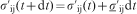
model, the total stress tensor 
The deviatoric stresses for material which exhibit elastic plastic is integrated
incrementally in time

Plasticity is treated using the Johnson–Cook material model. The
von Mises tensile flow stress is given by

 is the equivalent plastic strain and
 is the dimensionless plastic strain rate
for
is the dimensionless plastic strain rate
for
 s−1. The homologous temperature
is
s−1. The homologous temperature
is
 , where T is the absolute
temperature, Troom is the room temperature and Tmelt
is the melt temperature.23
, where T is the absolute
temperature, Troom is the room temperature and Tmelt
is the melt temperature.23
SPH method
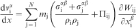
The kernel function is used in the numerical calculation. The discrete
form of momentum equation invoked with IFORM = 5 applies
for fluid material. It is given as
Simulated model
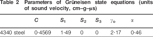
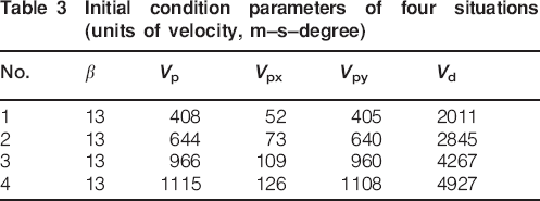
The plane strain numerical model of the oblique impact is shown in Fig. 2. The sizes of the flyer plane and baseplate were the same. The SPH particles were used. The size of the particle was (1·5×10−3)×(1·5×10−3) cm. A 4340 steel was used as the material of flyer plate and baseplate. The material parameters of Johnson–Cook model and Gruneisen state equation are shown in Tables 1 and 2. Four different velocities of flyer plate were considered in the simulations. The parameters of the initial conditions are listed in Table 3.
Parameters of Johnson–Cook equations (units, cm–g–μs)

Parameters of Grüneisen state equations (units of sound velocity, cm–g–μs)
Initial condition parameters of four situations (units of velocity, m–s–degree)
Results and discussion
Figure 3a shows four microstructures of steel to steel collision welded interfaces at different velocities of flyer plate.25 Figure 3b shows four photos of simulated interfaces. Comparing Fig. 3a with Fig. 3b, much similarity can be observed.
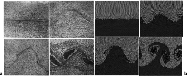
(a) Various microstructures; (b) Various simulated interfaces
Process of interface wave formation
In the no. 3 simulation, the oblique impact process is shown in Fig. 4. The interface waves and re-entrant jet appeared clearly.
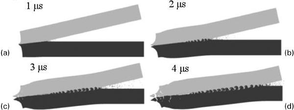
Numerical results at different times. (a) The simulated result at 1
The observation of a single wave formation is shown in Fig. 5a–d. Compared with the interface wave mechanism proposed by Bahrani et al., 7 there are some consistencies. In Fig. 5e–h, the interface wave formation mechanism proposed by Bahrani et al. 7 could be briefly introduced. It bases on the assumption that the base plane is perfectly rigid and the re-entrant jet all come from the flyer plane. When the re-entrant jet is completely choked, the stagnation point moves from the trough to the crest of the wave as shown in Fig. 5e. The high pressure at the stagnation point will depress and elongate the hump so that a forward trunk is formed. As the hump continues to move downstream, the stagnation point descends the forward slope of the hump as shown in Fig. 5f. As the re-entrant jet descends the forward slope of the hump, a second stagnation point is formed and part of the jet enters the cavity under the trunk, causing a vortex. As the new stagnation point moves forward, a new hump forms. The re-entrant jet is lifted upwards and is finally intercepted by the hump, as shown in Fig. 5g. The trapped re-entrant jet forms a vortex at the back of the hump as shown in Fig. 5h, and then a loop will go. Compared with the simulation results, Fig. 5a–c corresponds to Fig. 5e–g. The front vortex and behind vortex have formed in Fig. 5d. The main difference is that in the simulations, the re-entrant jet particles come from both plates, which may be more consistant with the facts.
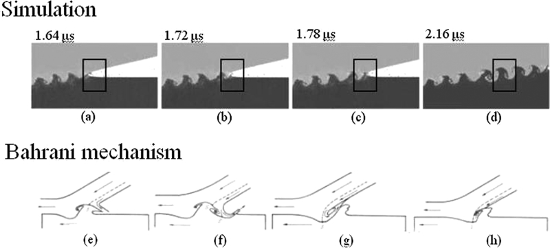
(a) The simulated result at 1.67 µs; (b) the simulated result at 1.72 µs; (c) the simulated result at 1.76 µs; (d) the simulated result at 2.16 µs
Discussion of explosive welding mechanism
Four different velocities of flyer plate were considered in the simulations. The collision angle β was kept as a constant. As the velocity of flyer plate increased (Table 3), the shape of combination interface changed from straight line to wave (Fig. 6a–d).
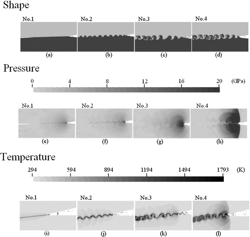
(a) The interface shape of No.1 situation; (b) The interface shape of No.2 situation; (c) The interface shape of No.3 situation; (d) The interface shape of No.4 situation; (e) The pressure distribution of No.1 situation; (f) The pressure distribution of No.2 situation; (g) The pressure distribution of No.3 situation; (h) The pressure distribution of No.4 situation; (i) The temperature distribution of No.1 situation; (j) The temperature distribution of No.2 situation; (k) The temperature distribution of No.3 situation; (l) The temperature distribution of No.4 situation
The pressure is much higher in the collision area than in the other areas,
and the pressure increases as the velocity of the flyer plate increases. If
the relationship exists, the temperature is calculated by
Fig. 6i–l shows that the re-entrant jet particles that escaped are almost all melted. Fig. 6i shows that there is no interface wave and no melted particles in the bonding interface. In this case, it is consistent with the factures of the solid phase welding. The Fig. 6j–l shows that some melted particles are stored in the bonding interface and the interface wave are formed. The deformation of the vortex become larger and the number of melted particles increases as the velocity of flyer plate increases. Fig. 6l shows the wavy interface with front and behind vortex and a lot of melted particles. In the central of vortex, there is a cavity caused by large deformation. If continued to increase the velocity of flyer plate, the melted particles would increase more and more. When the bonding interface in the collision area is densely covered with melted particles, it may be consistent with the characters of the fusion welding.
Explosive welding is a special kind of bonding which should not be simply attributed to a certain category of welding either to a fusion welding or to a solid phase welding, because in the collision area, there are both high pressure which is the solid phase welding characteristics and high temperature which is the fusion welding feature. Based on the study of metallographs at the bonding interfaces, Zhang26 proposed that explosive welding technology is a combination of diffusion bonding, fusion bonding and pressure welding. This argument is considered more reasonable.
Conclusions
SPH method could simulate the oblique impact process of explosive welding clearly. Most real phenomena of explosive welding could be reproduced in the simulation, such as the re-entrant jet and the interface wave. Therefore, it is helpful for us to study the mechanism of explosive welding by simulating high speed and internal finely flowing process, which is invisible in experiments. The simulation results show some conclusions below:
Explosive welding is different from a fusion welding or a solid phase welding. In the simulations, the features of high pressure and melted particles have been found. The thermal effects calculations were not considered. If the number of melted particles in the bonding interface was small, a fusion phenomenon may not happen in practice because of the thermal effects. A version proposed by Zhang26, in which explosive welding is a combination of diffusion bonding, fusion bonding and pressure welding, is considered to be more reasonable.
The mechanism by Bahrani et al. 7 is almost consistent with the simulated process of wavy interface formation. The main difference is that the particles of the re-entrant jet come from both flyer plate and baseplate in simulation, and this may be closer to the facts.
In addition, the SPH method provides a possibility to do a quantitative simulated research on explosive welding.
Footnotes
Acknowledgements
The authors gratefully acknowledge the financial support from the National Natural Science Foundation of China (grant no. 10902023).