
Abstract
The effects of positioning and clamping conditions of a specimen of friction stir spot welding are investigated in this paper in terms of axial force and torque generated during the process. For this purpose, two special designs of experimental set-ups embedding different positioning and clamping conditions are presented. A four-component mechanical sensor is used for the measurements. First, the effects of the rotational speed of the spindle and the plunge depth of the tool on the axial force and torque are studied. Second, the effects of positioning and clamping conditions are investigated through both set-ups designed, varying the spindle rotation speed. It is shown that the axial force and torque exhibit an important dependence with respect to the rotation speed of the tool and that their maxima depend on positioning and clamping conditions of the specimen.
Introduction
Friction stir spot welding (FSSW) is a solid state process, 1 1,2 extended from friction stir welding,3 which enables the welding of aluminium alloys. It creates a spot weld between two sheets by penetration of a rotating tool, composed of a pin and a shoulder, into the material. As the tool plunges into the material, heat is generated by friction between the tool and the material. The softened material beside the tool is then stirred and becomes mushy; a solid state bond is created at the interface of the upper and lower sheets, after which the tool is removed from the sheets. This process has been applied in the production of the Mazda RX-8 since 2003 for the assembly of the hood and rear door.2
The present paper focuses on the means of experimental implementation of the FSSW process. In the literature, the experimental implementation of FSSW is usually performed with instrumented milling or drilling machines.4– 8 The parts to weld are positioned and clamped in a vice or on a plane surface for experiments. However, this process is performed on industrial assembly lines with polyarticulated robots embedding a C frame device illustrated in Fig. 1. 1 9 1,9,10
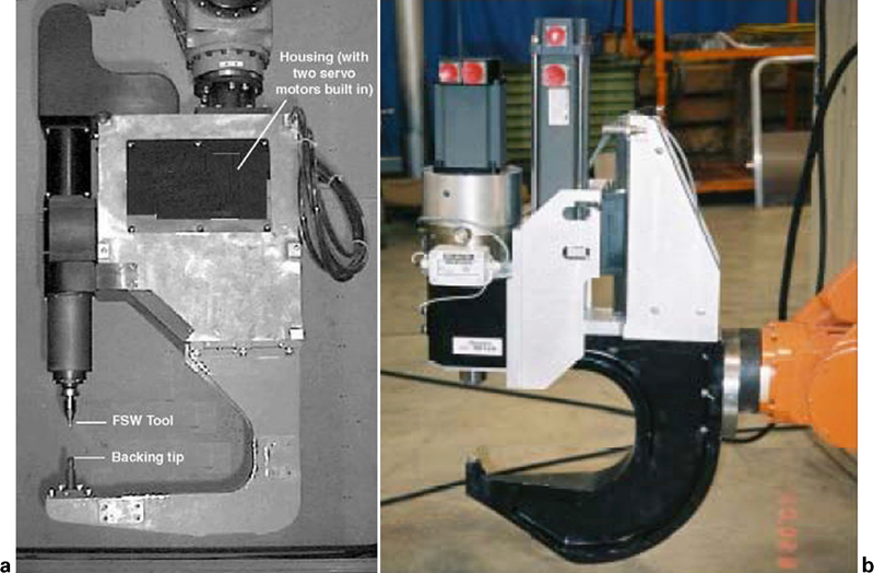
C frame device or spot FSW gun
This special device, also referred as a ‘spot FSW gun’, on which a tool is mounted, enables rotational and axial movements individually executed by servomotors; the welding sequence may be then controlled by the central processing unit of the robot system. A backing tip fixed face-to-tool enables the creation of a spot weld as the tool plunges into the material. The main advantage of a C frame device is that fixturing can be reduced because there is no need to resist any significant force on the part.10 Moreover, the robot can do spot welds whatever their orientations.
It is observed that positioning and clamping conditions are very different between a vice and a C frame device, and thus can lead to different effects on the weld joint quality since the deformed shape of the welded sheets can be different in both cases. Therefore, the study of the influence of the experimental implementation of the FSSW process on an operative weldability domain appears to be very interesting. Indeed, positioning and clamping conditions can have effects on the weldability domain as well as process parameters, geometries and materials of the tool and the specimen. Actually, to the authors’ knowledge this issue has not been investigated yet in the literature.
In this work, two experimental set-ups are designed for the investigation of the FSSW process. The design specifications embed different configurations for positioning. Those set-ups are mounted on a computer numerical control milling machine; thus the process is driven in displacement (position) control. Experiments are made with specimens of an AA 2024 aluminium alloy of 2 mm thickness. The studies carried out are focused on the analysis of the axial force and torque generated during the process, and on the influence of positioning and clamping conditions on these. The effects of the rotation speed of the tool and its plunge depth are also studied. It is shown that the axial force and torque exhibit an important dependence with respect to the rotation speed of the tool and that their maxima depend on the positioning and clamping conditions of the specimen.
Specifications
First, the design specifications have to be addressed. The aims of design of such devices are threefold:
to study the effects of process parameters on the weld joint integrity and on thermal and mechanical measurements, this means a special design incorporating the required instrumentation. Moreover, good and isostatic positioning and distributed clamping are required to minimise experimental uncertainties, to ensure a good repeatability of the process and to prevent further prestresses added in the specimen during the clamping operation
to enable and simplify the calibration of a numerical model with respect to data obtained from experiments.11 We address here the issue of the validation of the numerical simulation of welding processes. A real consistency is required between the design of the set-up and the numerical simulations performed
to quantify the effects of a change of a configuration for positioning on data measured and to assess the robustness of a model calibrated with respect to experimental data obtained from another configuration. This last point leads us to consider two configurations for positioning. Ones used are naturally those mentioned in the introduction, that is to say, the specimen placed on a plane surface and conditions equivalent to those of the C frame device. The other requires merging, in the same fixture, the positioning and clamping conditions of both a C frame device supported by a robot and the usual external fixture aimed at clamping the sheets to weld. Moreover, the plane surface device can make easier the calibration of a numerical model, since boundary conditions are simpler and the fixation is more rigid. Therefore, contact conditions between the specimen and the anvil can initially be approximated with prescribed displacements.
Design constraints
Two main design constraints arise from the design specifications listed above:
the assessment of forces and torques generated during the process is needed for the mechanical design of the devices but also for the choice of suitable mechanical instrumentation. Moreover, forces and torques generated may depend on process parameters and on geometries and materials of the tool and the specimen. For this purpose, a numerical simulation of FSSW could enable assessment of those efforts; however, the design of those set-ups aims to allow its calibration. Furthermore, though some authors have already performed force and torque measurements during the plunge stage of the weld,4, 12–15 it is still difficult to extract from the literature an accurate assessment of efforts generated for a given combination of material–geometry–process parameters
the ‘experimental simulation’ of a C frame device implies the positioning of an axial stop face-to-tool. Actually, this constraint proves difficult to treat as the design specifications issued have to be matched, that is to say, isostatic positioning and to prevent further prestresses being added to the specimen during the clamping operation. It is shown thereafter how to solve this problem.
Design of set-ups
Instrumentation
A four component mechanical sensor (KISTLER) is used for the mechanical measurements. This sensor is designed with a rotational geometry and is able to measure the three components of force and the axial torque. Afterward only the axial force and torque components will be considered.
Plane set-up
The specimen composed of two superposed sheets is supported on a plane surface. This solution is grafted on the mechanical sensor and takes full advantage of its rotational geometry. Actually, this kind of geometry enables efficient and accurate positioning of a component assembly by support plan/centring. The assembly is compact and thus rigid. Axial, radial and angular positioning of the specimen are respectively performed by means of a plane support (or backing anvil), a centring elastic sleeve mounted over a screw and a locating flat. A tightening cap clamps the specimen over the anvil and ensures distributed and homogeneous fixation while accommodating the important work area and thus may enable many welding points. The computer aided design model of this set-up is illustrated in Figs. 2 and 3, which show the set-up manufactured and assembled.
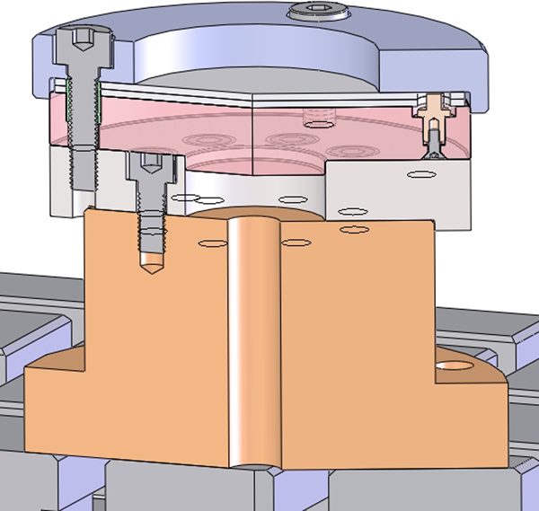
Computer aided design model of plane set-up: broken crossplane angular view
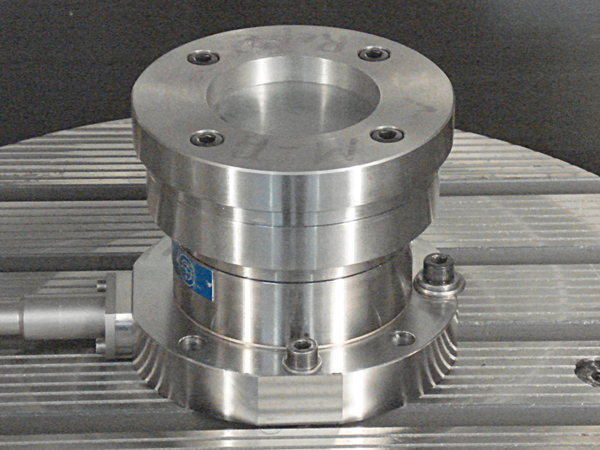
Plane set-up manufactured and assembled
The set-up parts have been manufactured in steel. The weld specimen is composed of two sheets designed as well with a rotational geometry. Each sheet is made of an AA 2024 aluminium alloy. Their manufacturing has been performed in two stages: they are first cut from sheets of aluminium by water jet cutting, and then functional surfaces are finished by wire electrical discharge machining.
Axial stop set-up
This second set-up aims at simulating operating conditions in a C frame device. Therefore, an additional point support, actually an axial stop, is implemented facing the welding area. Second, the machining of an undercut in the backing anvil and in the cap enables removal of contact surfaces between the specimen and those parts as far as possible from the centre of the welding area, in order to simulate the external fixture associated with a C frame device or other spot welds already made during the welding sequence. The reduced contact surface between the specimen and the set-up in the neighbourhood of the spot weld enables the specimen to deform more than that with the plane set-up. Furthermore, this solution preserves the advantages of the plane set-up, that is to say, the rotational geometry and thus the compactness and the accurate relative positioning of component assembly, the size of the welding area is not of interest here. The computer aided design model of the axial stop set-up is illustrated in Fig. 4.
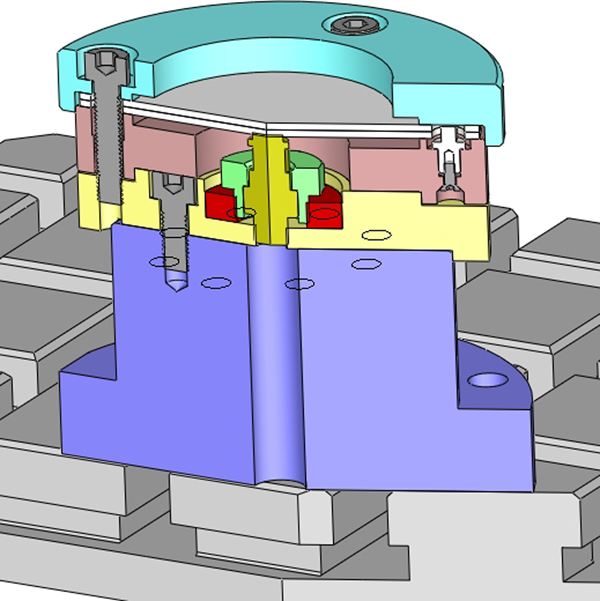
Computer aided design model of axial stop set-up: broken crossplane angular view
However, the introduction of an additional point support makes the positioning of the specimen modelled as hyperstatic. To remove the extra static unknown, a simple control system of the axial position of the axial stop is embedded in the device. This is adjusted by means of a threaded connection, after which a locknut clamps the system. This system is implemented in the base of the set-up, the part which enables the positioning of the set-up on the mechanical sensor. The control system of the axial stop position has been mechanically designed to support a load of ∼15 kN, while the maximum axial load allowable by the head of the machine spindle is ∼8·5 kN.
It is noted that an imprint can be machined on the upper face of the axial stop to make a decorative logo as by Pan et al. 15
Experimental
Experimental procedure
The tool geometry used is simple in order to make easier the calibration of a numerical model in the future. The tool is composed of a non-threaded conical shaped pin and a shoulder. The shoulder diameter is fixed to 8 mm and the upper diameter of the conical pin is 3·5 mm while the cone angle is 20°. The tool is made of tungsten carbide; Fig. 5 shows the hooping of the tool and its geometry.
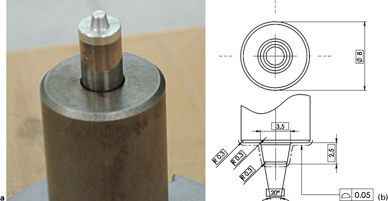
Friction stir spot welding tool geometry
Considering displacement control of the tool, the process parameters identified are the rotation speed of the spindle, the plunge depth and the plunging speed of the tool and the stirring duration. However, due to the high axial force generated during the process, the plunging speed of the tool cannot be investigated with this machine. Afterwards, the plunging speed is set at 10 mm mn−1. Moreover, as this study focuses on axial force and torque responses, the stirring duration is not investigated and is set thereafter for 4 s.
Therefore, the experiments have been performed varying the rotation speed of the spindle and the plunge depth of the tool. The latter is parameterised thereafter with the parameter δ illustrated in Fig. 6. This parameter has to be greater than or equal to zero; its value is calculated by the machine from the datum taken on the upper face of the backing anvil or the axial stop with a probe. The datum is recomputed after every set-up change.
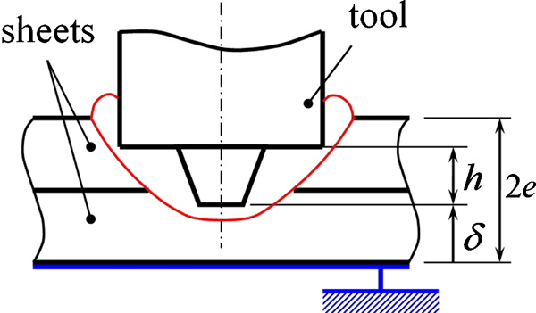
Plunge depth parameterisation
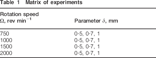
The rotation speed of the spindle ranges from 750 to 2000 rev min−1 and the opposite depth parameter δ ranges between 0·5 and 1 mm. The matrix of experiments performed is summarised in Table 1. Moreover this experimental sequence has been carried out for both set-ups designed, which in all 40 tests have been performed including repeatability tests.
Matrix of experiments
During the procedure, the tool stops 2 mm above the specimen to start acquisition of the mechanical sensor. The acquisition frequency is set to 1 kHz. Throughout the tests, controls are performed to ensure the stability of experimental conditions: control of the tool axial gauge, control of integrity of the set-ups by checking the axial position of the datum and cooling the set-ups to limit errors due to variations of thermal conditions.
Experimental results
The wide welding area accommodated by the plane set-up allows several weld points to be made on the same specimen. Figure 7 shows the welding stage of a spot weld and a specimen (two superposed sheets) joined with five spot welds. However, it appears that eccentric joints lead to an excessive noise in the acquisition of the axial force due to the position of the quartz within the mechanical sensor. Results of tests presented thereafter are performed with one spot weld made at the centre of the welding area.
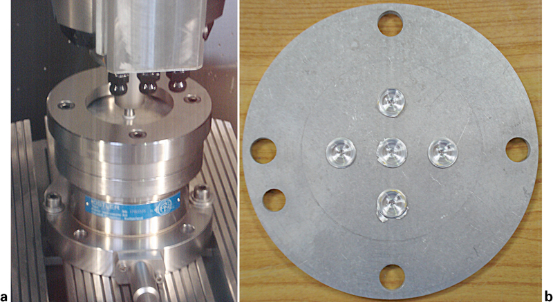
Friction stir spot welds
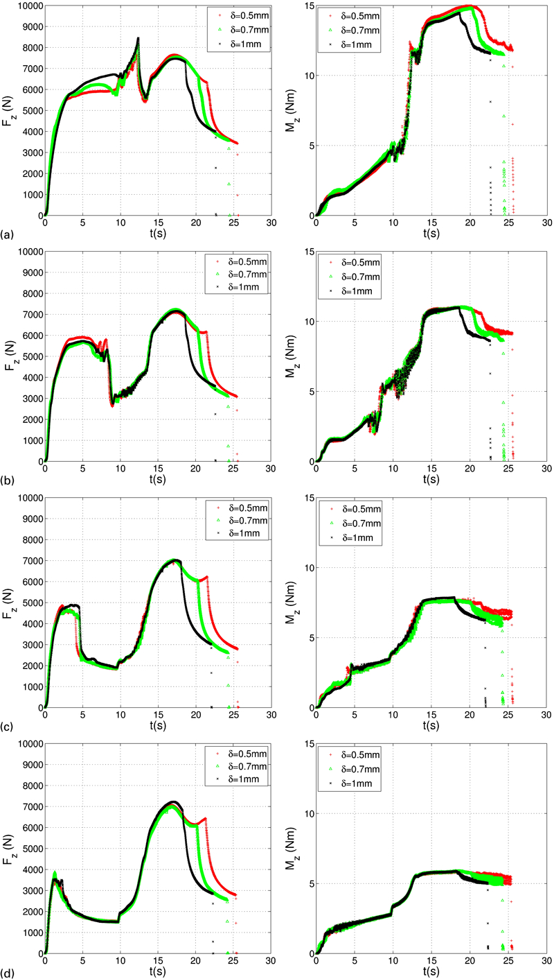
A comparison of axial force Fz and torque Mz evolutions at different plunge depths with the plane set-up is presented in Fig. 8. It is recalled that the parameter δ associated with the plunge depth is measured from the bottom of the specimen. Transverse forces, though recorded, are not presented here; they oscillate around zero during the process.
Axial force and torque comparison at different plunge depths with plane set-up
First, the axial force is composed of two peaks. This is linked to the geometry of the tool used. The first peak occurs as soon as the pin of the tool contacts the material. As it plunges, the heat generated by friction and stirring makes the material locally mushy, accordingly the axial force drops. As the shoulder contacts the upper face of the specimen, the friction area sharply increases, hence axial force and torque jump drastically, and the force reaches a maximum of about 7–8 kN. Once the plunge depth has been reached, the tool remains at the same position and stirs the material. The high rates of deformation and the heat generated soften the material as the temperature increases, and thus it is observed that the axial force and torque decrease in a parabola. This trend is consistent with axial force and torque measurements already reported in the literature. 4 4,8 Axial force and torque depend significantly on the rotation speed of the spindle. Though the second peak of the axial force changes little, the first one characterising the plunge of the pin into the material falls as the rotation speed of the spindle increases. In the same manner, the maximum torque reached as the shoulder plunges into the material decreases from 15 to 6 Nm, almost linearly with increasing rotation speed of the tool.
It is very interesting to observe that the torque trend is strictly increasing until the dwell stage, whereas the force exhibits these two peaks. This can be explained both by the material state beneath the tool and the friction conditions at the tool/material interface: before the first peak of the force, axial force and torque both increase suggesting that the friction conditions can be equated to dry friction. Then, as the force falls, the torque still continues to increase. A transition of the material state beneath the tool occurs to a viscous nature, thereby changing the friction conditions. Indeed, as the material is heated and softens, its mushy state tends to a very viscous fluid behaviour. During the process both mushy and solid phases coexist within the structure. This kind of fluid–solid coupling is the subject of a numerical model. 11 11,16
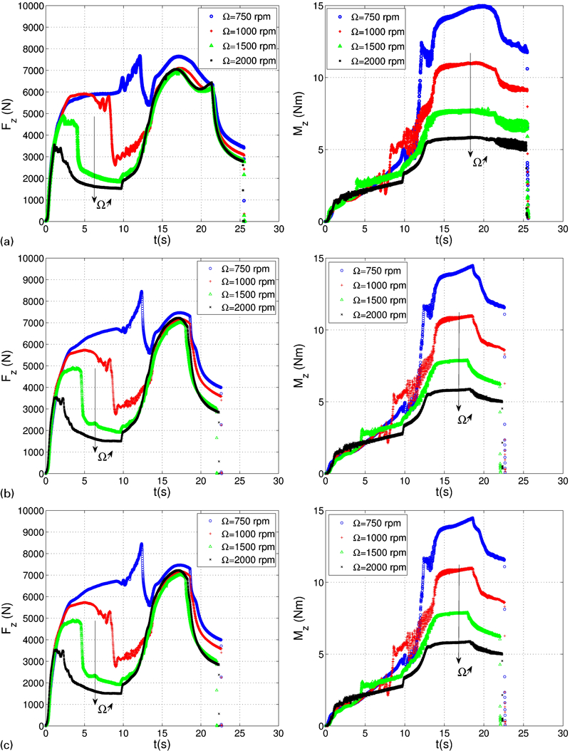
In Fig. 9, a comparison of axial force and torque evolutions at different rotation speeds obtained with the plane set-up is presented. Apart from the longer duration of the process due to the displacement control of the tool, the plunge depth effects on axial force and torque curves are small. An additional vertex appears in the force curves as the shoulder plunges into the material, between the second peak and the dwelling stage (parabola), which is even more pronounced as the rotation speed and the plunge depth of the tool increase. This effect remains to be explained.
Axial force and torque comparison at different rotation speeds with plane set-up
Furthermore, repeatability tests have been performed in order to assess the stability of the force and torque responses during the process. Figure 10 shows a repeatability test made from five trials performed with the plane set-up with the following parameter values: Ω = 1500 rev min−1 and δ = 0·7 mm. The displayed frequency of acquisition points has been reduced on this figure for readability. It is observed that the process exhibits quite good repeatability. The error bars are ∼300 N and 0·6 Nm at the force and torque maximum values. The ratio of these uncertainties with respect to the nominal maximum values gives relative uncertainties of ∼4·3% for the maximum force value and 8% for the maximum torque value. The uncertainties are higher in areas of strong variations of force and torque, which is the plunge of the pin and when the shoulder contacts the material.
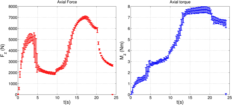
Repeatability test with plane set-up, Ω = 1500 rev min−1, δ = 0·7 mm
A series of identical tests were conducted with the axial stop set-up. Figure 11 shows a comparison between axial force and torque curves obtained with both set-ups designed. Those results are presented varying the rotation speed of the spindle and setting the parameter δ to 0·7 mm.
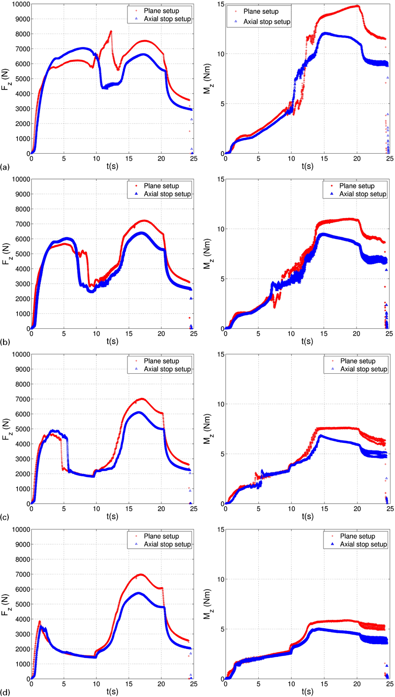
Axial force and torque comparison obtained with plane and axial stop set-up
It can be observed that a difference between force and torque maxima values appears between both positioning and clamping conditions. Whatever the rotation speed value of the spindle, the force and torque maxima values are greater with the plane set-up. Actually, this comes from the fact that the specimen is more rigidly clamped with this set-up, and can deform less. Moreover, it appears that the first force rise occurs slightly before the case of the plane set-up with respect to the axial stop set-up, and shifts the rest of the curve. This can be explained by the elastic deformation of the axial stop system, less rigid than a plane surface.
Figure 12 shows the force and torque maxima for both set-ups varying with the rotation speed of the spindle and the plunge depth. This illustrates the important effect of the rotation speed whereas the plunge depth has almost no effect on those quantities.
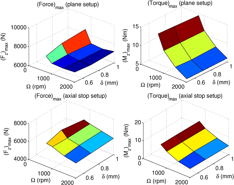
Force and torque maxima varying with rotation speed Ω and parameter δ
Those differences on extreme values seem a priori not very important, ∼1
kN at the force maximum and vary from 1 to 3 Nm at the torque maximum value
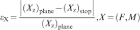
according to the rotation speed of the spindle. A normalised error between
force and torque maxima is computed as follows
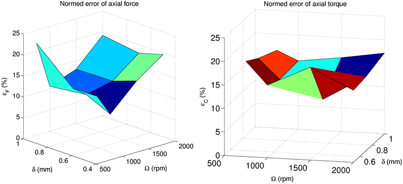
Normalised error on force and torque maxima varying with Ω and δ
Moreover, it is recalled that tests have been performed with sheets of 2 mm thickness, which are more than usual body sheet metal used in the automotive industry, and with an AA 2024 aluminium alloy, which is known for its high strength. Those severe test conditions lead to sheets deforming minimally, hence the deformed shape of the specimens are close for both positioning and clamping conditions. It follows that the differences between force and torque maxima obtained with both set-ups are not very important. Therefore, the differences exhibited can be considered as lower bounds.
Those differences measured may lead to some changes occurring during the formation of the weld joint, hence on its quality. Destructive mechanical tests, as single lap shear tests, have to be performed in order to verify if the failure load varies accordingly.
Conclusions
In this study, two special set-ups have been designed for the investigation of friction stir spot welding. The aims of designing such devices are:
to study the effects of process parameters on the weld joint integrity and on mechanical measurements
to enable and simplify the calibration of a numerical model with respect to data obtained from experiments
to quantify the effects of a change of positioning and clamping conditions on data measured and to assess the robustness of a model calibrated with respect to experimental data obtained from another configuration.
The plane set-up, supporting the specimen on a plane surface, and the axial stop set-up, embedding an axial stop face-to-tool, have been designed to simulate operating conditions respectively performed with a vice and a C frame device, systems usually used for FSSW. Those devices are mounted on a four-component mechanical sensor designed with a rotational geometry, and thus take full advantage of it.
Subsequently, the studies carried out have been focused on the analyses of the axial force and torque generated during the process, and on the influence of positioning and clamping conditions on these, varying the rotation speed of the tool and its plunge depth. From this study, it can be concluded as follows.
The axial force trend is not monotonic and exhibits two peaks associated with the plunge of the pin and the shoulder of the tool, whereas the axial torque is monotonic until the dwell stage. Those trends are in accordance with measurements already reported in the literature.
The first peak of axial force and the torque maximum exhibit an important dependence with respect to the rotation speed of the spindle.
It appears that there are almost no effects of the plunge depth on mechanical measurements.
The process exhibits good repeatability.
Positioning and clamping conditions affect the axial force and torque measured. Normalised errors on force and torque maxima vary in the range of 10–20% according to process parameters, which is greater than relative uncertainties found during repeatability tests.
Considering the thickness of the sheets (2 mm) and the high strength of the AA 2024 aluminium alloy used, the differences exhibited between measurements performed with both set-ups can be considered as lower bounds.
The mechanical measurements performed represent a first step. In the future, this work will be extended by performing further mechanical tests including destructive tests, metallurgical and thermal analysis. Those studies aim to feed an experimental database, which will enable in the long term the calibration of a numerical model.
Footnotes
Acknowledgements
The authors would like to acknowledge the pôle productique of the Ecole Nationale d'Ingénieurs de Saint Etienne for its financial support and for machines made available. They also want to thank the technicians Luigi Mintrone and Patrick Polly for the manufacturing of the experimental set-ups.