
Abstract
Full penetration 15 kW Yb fibre laser butt welding of thick AlMg3 (AW 5754) plates was performed in PA position. A contactless inductive electromagnetic weld pool support system was used to prevent gravity dropout of the melt. The welding speed needed to achieve 20 mm penetration was ∼0·5 m min−1. An ac power supply of ∼244 W at 460 Hz was necessary to completely suppress gravity dropout of the melt and eliminate sagging of the weld pool root side surface. The oscillating magnetic field can suppress the Marangoni convection in the lower part of the weld pool. The system was also successfully used in the full penetration welding of 30 mm thick AlMg3 plates.
Introduction
The advantages of laser beam welding, such as high welding speed and low heat input, are well known. The laser beam forms a narrow weld pool with nearly parallel side walls. During solidification of a weld pool, longitudinal and transverse shrinkage stress variations through the thickness of the material are much lower than in most other welding technologies. This results in very low buckling and bending of the workpiece.1 Especially, a high quality of welded joints is achieved in full penetration keyhole laser welding. Full penetration can effectively suppress the development of the so called process porosity due to keyhole instability near its bottom tip.2 This type of pore is particularly associated with partial penetration welding; its occurrence is sharply reduced when full penetration welds are produced.3
Modern industrial Yb fibre and disc lasers with output powers of up to 20 kW can perform single pass welding of up to 16 mm steel parts.4 However, from a penetration depth of 20 mm and onwards, the gravity force becomes a process limiting factor for full penetration welding in PA position.
The hydrostatic pressure in the melt increases with increasing plate thickness h

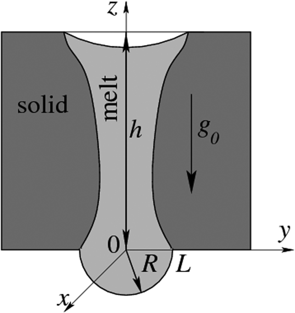
Pressure balance in weld pool
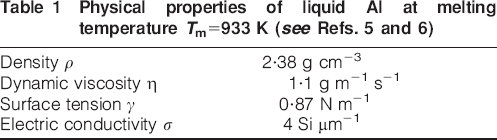
Physical properties of liquid Al at melting temperature Tm = 933 K (see Refs. 5 and 6)
Gravity dropout takes place when the hydrostatic pressure exceeds that of surface tension


In the present study, full penetration butt welding of up to 30 mm thick AlMg3 plates was performed in PA position using an electromagnetic (EM) weld pool support system. Numerous systems for EM fluid flow control of molten metal containing very large volumes of liquid metal (some kilograms) are widely used in many industrial processes: casting, crystal growth, electrolysis, etc., see e.g. proceedings of two EM processing of materials conferences cited in Refs. 7 and 8. Electromagnetic processing of material technologies can be used to:
stabilise (EM shaping) or destabilise (EM pulverisation) the surface of solidified metal
accelerate (EM stirring) or decelerate (Hartmann effect) convective flows in the melt
refine the melt (EM rectification).
In the present study, EM forces were used to prevent gravity dropout of the melt. The concept of EM weld pool support in laser beam welding was developed at the Institut für Strahlwerkzeuge, University of Stuttgart.7– 10 The system was successfully tested in CO2 laser and Yb disc laser beam welding of up to 12 mm thick AISI 316L stainless steel plates in PA position. The ac power needed to completely eliminate sagging of the lower weld pool surface was found to be ∼1·1 kW per 1 cm of the plate thickness. The optimal frequency was 3 kHz.
The thermal conductivity of liquid Al is much higher than that of liquid steel. Reference welding tests (without EM weld pool support) carried out within the scope of this study using 15 kW laser power have shown that the welding speed needed for full penetration is ∼0·3 m min−1 for 30 mm thick AlMg3 plates. The weld pool width becomes very large, i.e. up to 30 mm. The intensity of thermocapillary (Marangoni) convection is extremely high for both weld pool surfaces. However, the magnetic field can be used also to suppress any convective flow in the weld pool (Hartmann effect, see equation (13)).
Physical background
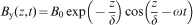
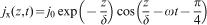
The inductive EM weld pool support system utilises eddy currents produced by an oscillating magnetic field generated by an ac magnet located under the sample (see Fig. 2). Two magnet poles of the ac magnet are located on the left and right sides the weld pool. The externally applied magnetic field B is directed perpendicularly to the welding direction (x axis), whereas the electric current density

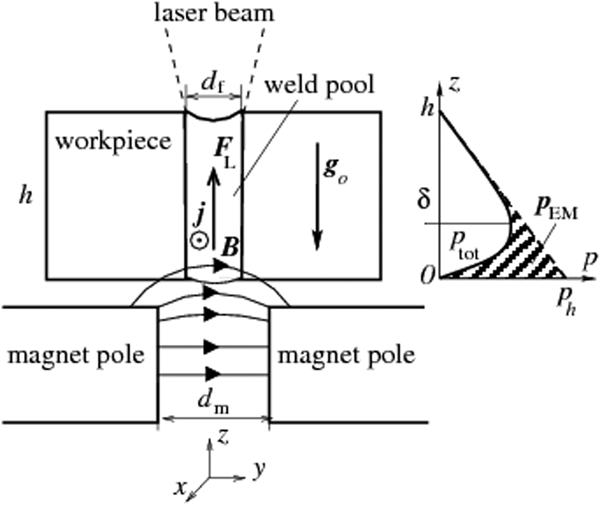
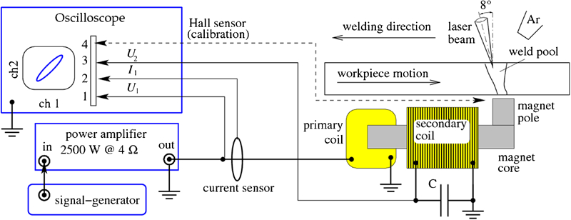
Scheme of inductive EM weld pool support system; diagram (right) illustrates pressure balance in melt
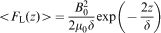
A qualitative description of the weld pool support process can be obtained using the classical skin effect theory.11 First, neglect the temperature variation of the electric conductivity σ and suppose that the magnet pole cross-sections and the gap between them dm are much larger than the weld pool width df and the skin depth, i.e.

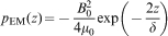
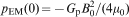
The Lorentz force averaged over time is

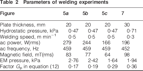
Parameters of welding experiments
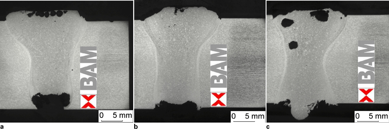
Cross-sections of full penetration 15 kW Yb fibre laser butt welds in 20 mm thick AlMg3; parameters of EM weld pool support are listed in Table 2
To prevent the development of intensive weld pool stirring, the Lorentz force field must be as uniform as possible. First, all the characteristic dimensions of magnet poles (the pole cross-section and the gap between poles) must be much larger than the width and length of the weld pool. The magnetic field in the vicinity of the magnet pole edges is very non-uniform, and this effect results in a large non-uniformity of the magnetic pressure. The second source of electromagnetically driven convective flows in the melt is the temperature dependence of the electrical conductivity σ. Both of these effects can intensify undesirable EM stirring in the weld pool.
12
12,13 Electromagnetic processing of material technologies can be used to suppress all convective flows in the melt. In particular, the EM contribution to the effective viscosity (Hartmann effect) is ∼σ(BL)2. This value rapidly increases with increasing both the rms value of the magnet field B and the characteristic scale of convective motion L (half-width of the weld pool). The relation between the EM contribution and the normal (dynamic) viscosity η is known as the Hartmann number12

Experimental set-up
All welding experiments (butt welding in PA position without filler wire) were performed using an Yb fibre laser YLR-20000 at the laser output power of 15 kW. To prevent optical feedback, the incident angle of the laser beam was taken to be 8° to the vertical (see Fig. 4). The laser optics has the following parameters: the diameter of the beam delivery fibre is 0·2 mm, and the output aperture is 35 mm. The collimation and the focal length are 125 and 350 mm respectively, which result in the focal spot diameter of 0·6 mm (theoretically). The focal position is −2 mm (under the surface). The shielding gas (industrial grade argon, 20 L min−1) was supplied to the top of the weld pool behind the laser beam.
Experimental set-up
All the welds were produced by traversing the sample relative to the laser optic head and the ac magnet, which were mounted stationary (see Fig. 4). The distance between the magnet poles and the sample was 2 mm. The gap between the magnet poles must be large enough to allow free outflow of the laser beam for full penetration and avoid damage of the ferromagnetic material by contact with the plasma plume and with hot metal spatter. Additionally, the magnet poles were protected by calcium silicate plates (Duratec). The gap between the magnet poles was taken to be 25 mm, and the cross-section of both magnet poles was 25×25 mm. Both primary and secondary coils were mounted on the magnet core made of 0·05 mm thick Fe–Si lamination (Microsil).
An oscilloscope was used to control the output voltage and current as well as the phase shift between them. The capacitor C was connected parallel to the secondary magnet coil and was used to compensate for the reactive power.
The voltage on the secondary coil U2 was measured and used to control the ac magnet field between the poles. A series of calibration tests were performed before starting the laser power. A Hall sensor was placed ∼2 mm under the workpiece in the middle of the gap between the magnet poles.
The most important part of the analysis preceding the welding tests was the choice of the optimal ac frequency f0≈460 Hz. As noted in the previous section, the distance between the weld pool and magnet poles (25 mm) must be larger than the skin depth δ of cold metal. For AlMg3, σ(T = 273 K) = 20 Si μm−1, i.e. δ(cold) = 5·3 mm (see equation (6)). The next problem is EM suppression of the Marangoni convection (see equation (13)). To provide an effective deceleration of the flow deep in the weld pool, the skin depth should be about the width of the weld pool. The electric conductivity of liquid AlMg3 is σ(liquid)≈4 Si μm−1 and δ(liquid) = 12 mm. This analysis shows that the applied ac magnet can provide an EM support of up to 12–14 mm wide weld pools.
Results and discussion
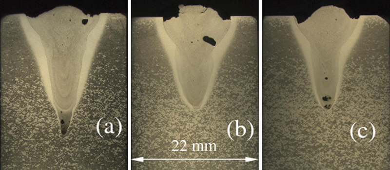
All the welding experiments were performed using 15 kW laser beam power. Figure 4 shows the results of reference (without EM support) welds obtained in partial penetration bead on plate welding of 40 mm thick AlMg3 plate in PA position. Large process pores are observed in all regions of the weld. Clusters of small pores are observed in the bottom region of the two welds. Additionally, many small (<1 mm) pores are detected near the weld centreline. Widening of the upper region and very irregular weld surfaces relate to a very intensive Marangoni convection.
All the welding experiments with EM weld pool support were carried out in butt joint configuration with zero gaps. It was found that full penetration takes place at welding speeds of 0·5 and 0·3 m min−1 for 20 and 30 mm thick plates respectively. The next series of experiments were undertaken at different values of ac power to determine the equilibrium conditions for hydrostatic pressure compensation in the weld pool. The results are listed in Table 2.
Figure 5 shows the typical cross-sections of welds produced with EM weld pool support. Test weld 5a was produced using 279 W ac power. This value is larger than the power needed to compensate for the hydrostatic pressure (470 Pa). The EM pressure pressed the surface of the melt deep into the weld pool. Test weld 5b (244 W ac power) shows a small overcompensation of the gravity forces. Both of these welds show Y-like shapes of weld cross-sections: the Marangoni convection is very active in the upper parts of the weld pool but does not affect the root region. One of the possible explanations of this fact is the Hartmann effect (see equation (13)). The Hartmann number rapidly increases with increasing characteristic scale of the convective flow L. For the weld shown in Fig. 5b [B = 77 mT(rms) and half-width of weld pool L = 5 mm], the Hartmann number is Ha2 = 550, i.e. EM suppression of the Marangoni convection in the lower part of the weld pool is more than two orders of magnitude higher than viscous effects. The skin depth δ = 12 mm is much smaller than the thickness of the welded plate, i.e. the EM field does not affect the Marangoni convection near the upper surface of the weld pool.
Reference welds (B = 0)
For a better understanding of the magnetohydrodynamical phenomena in the weld pool, we have performed computer simulations of the process.14 These simulations show that the ac magnetic field can drastically reduce the width of the lower region of the weld pool.
Both cross-sections in Fig. 5a and b show a thick oxide layer on the upper surface of the weld. The gas bubbles can easily reach the upper surface, but they cannot escape from the weld pool and remain captured in the resolidified melt. The standard methods used to eliminate the oxide layer are dry machining of the welded parts immediately before welding and using a low moisture shielding gas.3 This preparation can also reduce the level of hydrogen porosity. However, the main objective of the present study was to test the EM weld pool support system. The ac magnet field does not affect the upper weld pool surface, and all methods used to remove the oxide layer from the upper workpiece surface can be tested and optimised independent of the weld pool support system.
For the weld shown in Fig. 5c, the applied ac power of 166 W cannot support and stabilise the weld pool. Root sagging of ∼4 mm is observed. The lower weld pool surface becomes unstable. Very large gas bubbles are captured by the melt and flow to the upper surface. A further decrease in ac power results in weld pool instability.
The same ac magnet was used for welding 30 mm thick plates using 15 kW laser power. Figure 6 shows the weld produced with and without weld pool support. This photo clearly demonstrates the importance of weld pool support. An attempt to weld without support results in a complete drop through of the liquid metal.
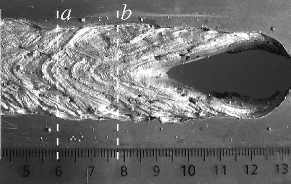
Top weld bead obtained in welding of 30 mm thick plates with EM weld pool support: dashed lines mark positions of cross-sections shown in Fig. 7; last 5 cm of weld was produced without weld pool support
Figure 7 shows two X-like shapes of weld cross-sections obtained with optimal ac power supply (see process parameters in Table 2). Note the slight overcompensation of sagging at the outer border of the weld pool. This effect is a consequence of the non-uniformity of the ac magnetic field near the edges of the magnet poles: the gap between the magnet poles (25 mm) was of the same order as the width of the weld pool. The magnetic field near the pole edges is very non-uniform. This non-uniformity results in a large rotational (rot FL≠0) contribution to the Lorentz force field and, as a consequence, in very intensive EM stirring, which can deform or even destabilise the surface of the melt.11 To improve the uniformity of the applied magnetic field, it is intended to use another magnet with 50×50 mm magnet pole cross-section and up to 50 mm gap between poles. This modification of the ac magnet must be performed before starting full penetration welding experiments using 20 kW laser power.
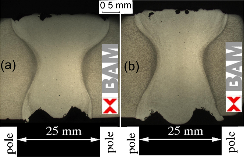
Two cross-sections of full penetration 15 kW Yb fibre laser butt welds in 30 mm thick AlMg3 with EM weld pool support: gap between magnet poles is of same order of magnitude as width of weld pool
Conclusions
The results of full penetration high power laser beam butt welding of up to 30 mm thick AlMg3 plates in PA position were presented. An inductive contactless EM weld pool support system was successfully used to prevent gravity dropout of the melt.
Full penetration was observed to occur at 0·5 or 0·3 m min−1 welding speed for 20 or 30 mm plate thickness respectively. The EM weld pool support system operating at 460 Hz needs ∼200 W ac power to prevent outflow from up to 30 mm deep and 25 mm wide weld pools.
In PA position welding, the gas bubbles appearing due to keyhole instability can easily reach the upper surface of the weld pool. However, a thick oxide layer holds the bubbles on the surface of the melt. Since the ac magnet field does not affect the upper surface of the weld pool, all standard methods of eliminating surface oxide layers can be used to solve this problem.
The results of the welding experiments performed with EM weld pool support offer perspectives for the proposed technology. In particular, this technology allows deep penetration laser beam welding in PE (overhead) position.9