
Abstract
In order to investigate the durability of an Ir based alloy tool, friction stir welding (FSW) of 304 stainless steel plates was performed under various welding conditions, and the mechanical properties of the joints were measured. Defect free joints are possible under certain conditions, and the mechanical properties of the joints are the same as the base material. When the rotation pitch is ∼0·3, the degree of wear of the Ir based alloy tool with 1·4 mm probe height, which was used for the FSW of a 304 stainless steel plate with 2 mm thickness, was less than or equal to that of the polycrystalline cubic boron nitride tool with 2 mm probe height, which was used for the FSW of a 304 stainless steel plate with 9 mm thickness. The result of the tool life test in this study showed that the Ir based alloy tool enabled the FSW of 304 stainless steel over a 75 m length.
Keywords
Introduction
Stainless steels are widely used everywhere from consumer durables such as kitchens, home appliances, cars, trains and architectures for nuclear facilities, not to mention chemical plants under corrosive environment. These materials have excellent characteristics, such as high strength, high corrosion resistance, durability and relatively low production costs. However, it is generally known that fusion welding for assembling stainless steels creates problems such as strength deterioration of the joints, deformation due to distortion and corrosion. Friction stir welding (FSW) was invented in 19911 as a solid state joining method and produces joints with low distortion because the welding temperature is lower than the melting point of the workpieces.2 Furthermore, the strength deterioration in the joint is lower than that of fusion welding because grain refinement occurs due to stirring action by the welding tool. 3 3,4 Friction stir welding is an excellent welding method, which has the possibility to improve the problems of fusion welding. Such an excellent welding method must be applied to excellent materials, such as stainless steels, which constitute many constructions; therefore, the research and development of the FSW of stainless steels have been carried out aggressively.5– 13 It is a very important matter to select a welding tool material for the FSW of materials such as stainless steel with high strength and relatively high melting point. Until now, tool materials, such as high melting point metal,14– 16 tungsten carbide17– 19 and ceramic based tools,20– 23 have been developed and investigated as a tool with high heat resistance and high mechanical properties at elevated temperatures. These FSW tools have been reviewed in detail from several perspectives, such as tool material selection, tool geometry, load bearing ability, tool wear, deformation, failure and tool cost, by Rai et al. 24
The authors focused on iridium, which has a high melting point, high mechanical properties and oxidation resistance at elevated temperatures. Although the available supplies of Ir are very low, the demands are also low (∼3 tons/year).25 Therefore, it is thought that the supplies of Ir are not scarce at present. Since Ir is a rare metal, refining technology has been established, and the recycling of Ir is possible.26 The price of Ir metal is very high, about $35/g (as of November 2011). However, it is possible to reduce the cost of Ir metal by recycling or recasting, since their purchase except for new metal is almost unnecessary. As for the manufacturing process, Ir based alloys have a moderate hot workability. Electrical discharge machining and grinding can be applied to Ir based alloys, though cutting is comparatively difficult. Although the authors developed the Ir based alloy tool and succeeded in the FSW of 304 stainless steel, the details have not yet been clarified. 27 27,28 The objectives of this study are the clarification of the welding conditions of 304 stainless steel using an Ir based alloy tool and the investigation of the joint properties and tool life.
Experimental
Friction stir welding was performed using a position controlled machine. Figure 1 shows a schematic illustration of the Ir based alloy tool used in this study. The welding tool made of Ir–10Re–1Zr (at-%) with a 15 mm diameter shoulder, a 6 mm diameter probe and a 1·4 mm probe height was used with a tilting angle of 3°. Because this welding tool has an excellent oxidation resistance at elevated temperatures,28 the FSW was performed without shielding gas.
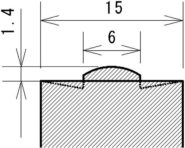
Schematic illustration of Ir based alloy tool
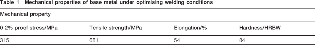
As for optimising the welding conditions and evaluating the joint properties, two SUS 304 stainless steel plates with 1·5 mm thickness, 50 mm width and 150 mm length were used as workpieces. The chemical compositions of the workpiece is 0·05C–0·53Si–0·92Mn–0·034P–0·001S–8·10Ni–18·09Cr (mass-%) and its mechanical properties is shown in Table 1. These workpieces were degreased after machining of the joint surface and then butt welded. The process parameters were varied from 13·8 to 50·0 rev s−1 in rotation speed and from 4·2 to 13·3 mm s−1 in travelling speed. The tool wear of the Ir based alloy tool was hardly observed during optimising of the welding conditions. The defects were checked by visual inspection and cross-section observations. The cross-sections perpendicular to the welding direction were polished and electrically etched by 10% oxalic acid solution, which were observed using an optical microscope and a scanning electron microscope. The tensile test and hardness distribution measurements were performed to evaluate the mechanical properties. During the experiment of the optimising welding conditions, several welds were obtained at the appropriate conditions, and these welds showed a similar appearance and microstructure; therefore, the mechanical properties of one weld were evaluated as being representative. Three 13B tensile test specimens were prepared according to JIS Z2201. They were cut out perpendicular to the welding interface from the same test plate without any mechanical surface treatment. The tensile tests were performed at a strain rate of 6·7×10−3 s−1 and room temperature. The hardness tests of the cross-section were carried out using a Vickers hardness tester at a load of 2·94 N. The hardness distributions were measured from the weld centre towards both sides of the base metal with 1 mm pitch at 0·7 mm height from the bottom surface of the workpieces.
Mechanical properties of base metal under optimising welding conditions
As for the tool life tests, the optimum conditions were selected based on the above experiments, and the stir in plate FSW was carried out several times with each welding length of 500 mm, and then the tool wear was checked by observation of the tool variation. SUS 304 stainless steel plates with 2 mm thickness were used for the tool life test. The probe height, the shoulder height and the probe diameter were measured to evaluate the tool wear. The tool wear was evaluated by the area reduction rate, i.e. (S−S0)/S0×100, where S and S0 are the cross-sectional area of the tool after the FSW and the initial cross-sectional area of the tool observed from a direction perpendicular to the rotation axis of the tool respectively.
Results and discussion
Determination of optimum welding conditions
Figure 2 shows the cross-sectional macrostructure of the joints that were obtained under various welding conditions. When a higher travelling speed at the same rotation speed was applied, groove-like defects appeared on the advancing side. When the travelling speed is faster than 10·5 mm s−1, an unwelded part, namely, the kissing bond, was found on the back side of the workpiece.29 Even if no defects are identified from the appearance inspection, it was found that a kissing bond exists on the back side of the joint.
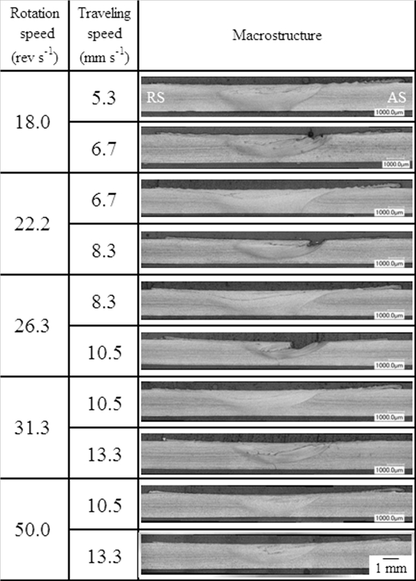
Cross-sections obtained under various welding conditions (AS: advancing side; RS: retreating side)
Under these circumstances, the appropriate welding conditions were found and are summarised in Fig. 3. During the FSW, the revolution pitch ( = travelling speed/rotation speed) is related to the heat input, and it is believed that the heat input decreases with increasing revolution pitch.30 The dashed line in Fig. 3 shows the revolution pitch of 0·3 mm rev−1. Thus, it is considered that the appropriate welding conditions are less than a revolution pitch of 0·3 mm rev−1 and less than a travelling speed of 8·3 mm s−1. When the travelling speed is over 10·5 mm s−1, and even if the revolution pitch is <0·3 mm rev−1, the kissing bonds are present as shown in Fig. 2c, though no defects could be visually observed. The reason for this is considered that the time to transfer frictional heat, which is generated between the shoulder and the workpiece, to the back side decreases with increasing travelling speed, though the details are not completely clear yet. On the other hand, it is thought that the kissing bonds can be suppressed by optimising the shape of the probe or increasing the plunge depth.
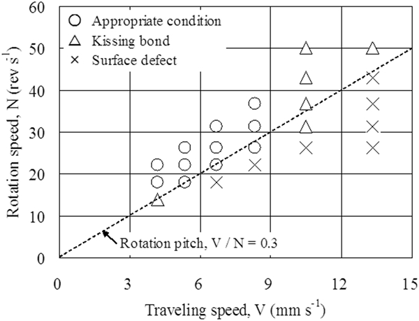
Appropriate welding conditions for butt joints
Cross-sectional observation of joints
Figure 4 shows the typical macrostructure of the joint obtained under appropriate welding conditions. The streaked layer that is etched easier than the surrounding area was observed across the stir zone. Such an easily etched region was also reported by Park et al. 6 6,7 and Ishikawa et al. 12 In this study, the polished cross-section was analysed by an electron probe microanalyser, and it was found that hundreds of nanometre diameter particles with higher concentrations of Cr, Si, Mn and O than the surrounding area were agglomerated, as shown in Fig. 5. During the FSW in this study, no shielding gas, such as argon, was used. Therefore, although it is postulated that these particles were oxides of additive elements in stainless steel and were taken into the joint by the stirring action of the tool, the details have not been completely clarified yet.
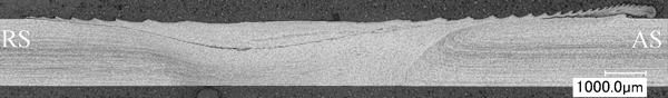
Typical macrostructure obtained under appropriate welding conditions
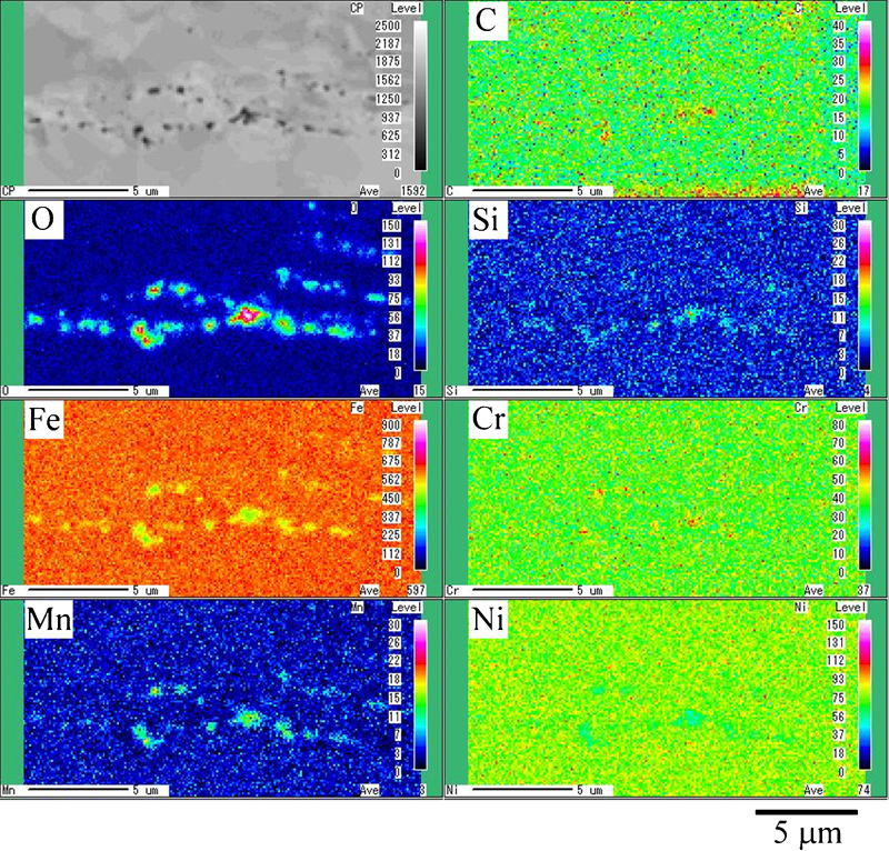
Electron probe microanalyser elemental maps of streaked layer
The relationship between the grain size of the stir zone and the welding conditions is shown in Fig. 6. The grain size decreases with the increasing travelling speed and the decreasing rotation speed, i.e. the decreasing heat input.
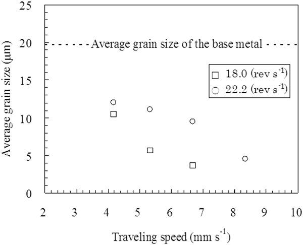
Relationship between grain size of SZ and welding conditions
Mechanical properties of joints
Figure 7 shows the hardness distribution of the joints obtained under various welding conditions. When the rotation speed is fixed at 22·2 rev s−1, the hardness profiles show little change, though the hardness in the stir zone becomes slightly higher than that of the base metal at the travelling speed from 4·2 to 6·7 mm s−1, but the hardness profiles in the stir zone increase at the travelling speed of 8·3 mm s−1. On the other hand, when the rotation speed is fixed at 18·0 rev s−1, an increase in the hardness is seen in the stir zone at the travelling speed from 5·3 to 6·7 mm s−1. Although direct proof has not been acquired, it is thought that it is because the finer grains shown in Fig. 6 contributed to the increase in deformation resistance.
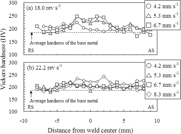
Hardness distribution on cross-section at different travelling speeds with rotation speed of a 18·0 rev s−1 and b 22·2 rev s−1
The tensile properties of the sound joints and those of the base metal are shown in Fig. 8. The joints that were obtained at the rotation speed of 18·0 rev s−1 with the travelling speed of 5·3 mm s−1 fractured in the base metal. The reason for this is considered to be influenced by the hardening in the stir zone. The increase in travelling speed and the decrease in rotation speed decrease the heat input and produce finer grains. At the rotation speed of 22·2 rev s−1, however, because a surface defect is generated at the travelling speed of 8·3 mm s−1, as shown in Fig. 2, the optimum welding conditions, that is, the fracture of the base metal, will exist between 6·7 and 8·3 mm s−1 travelling speeds. Under other conditions, almost all of the tensile specimens showed lower elongations than that of the base metal and were fractured in the stir zone, though they showed the same ultimate tensile strength and 0·2% proof stress as that of the base metal. This is because the thickness of the stir zone is slightly thinner than that of the base metal. Moreover, the reason for the reduction in fracture elongation is believed to be influenced by the hardening in the stir zone, as shown in Fig. 7.
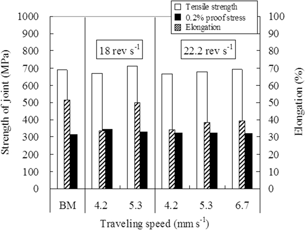
Tensile properties of joints under various welding conditions
Life test of Ir based alloy tool
The welding conditions to obtain sound joints (at the rotation speed of 22·2 rev s−1 along with the travelling speed of 5·3 mm s−1) and the critical welding conditions with the revolution pitch of 0·3 mm rev−1 (at the rotation speed of 18·0 rev s−1 along with the travelling speed of 5·3 mm s−1) were selected from Fig. 3; then, the wear test of the Ir based alloy tool was carried out by stir in plate FSW. Figure 9 shows the variation in shape of the tool during the wear test. The probe diameter significantly decreases with increasing welding distance. On the other hand, the probe height and the shoulder height hardly changed. Figure 10 shows the reduction rate of the cross-sectional area of the tool that was observed from a lateral view. In addition, the reduction rate of the cross-section of the polycrystalline cubic boron nitride (PCBN) tool with CS4 (convex scrolled shoulder step spiral) shape (application thickness range, 1·5–2·3 mm) when 304 stainless steel with 9 mm thickness is friction stir welded at the rotation speed from 3·3 to 13·3 rev s−1 along with the travelling speed of 1·0 mm s−1 is shown in Fig. 10.31 The rotation pitch, which is an index of the heat input, is almost the same between the welding conditions on the Ir based alloy tool (18·0 rev s−1 and 5·3 mm s−1) and the PCBN tool (3·3 rev s−1 and 1·0 mm s−1). Although an easy comparison cannot be made because the tool shape, the thickness of workpiece and welding conditions are different, the degree of wear of the Ir based alloy tool with 1·4 mm probe height, which was used for the FSW of 304 stainless steel with a 2 mm thickness, was less than or equal to that of the PCBN tool with ∼2 mm probe height, which was used for the FSW of 304 stainless steel with 9 mm thickness.
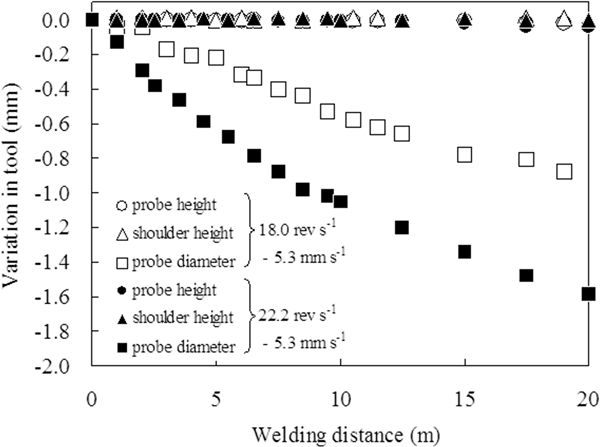
Relationship between variations in tool shape and welding distance
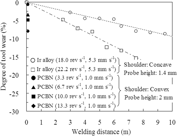
Relationship between variations in degree of tool wear and welding distance
Figure 11 shows the appearance of the probe and the macrostructure after the stir in plate FSW at the rotation speed of 22·2 rev s−1 with the travelling speed of 5·3 mm s−1. It is thought that there is a contamination of the tool component because the weight loss of the tool from 0·01 to 0·02 g per 1 m welding length was checked. It was possible to weld ∼20 m long without defects at the same tool plunge depth. When the welding distance exceeded 20 m, surface defects occurred. It is believed that this is due to the change in stirring action and heat input by the decrease in volume of the probe, as shown in Fig. 11b. Defect free joints were then obtained again by increasing the tool plunge depth. After many stir in plate FSW tests were performed with increasing tool plunge depth in this way, the probe did not break even if the welding distance reached 75 m, though an area reduction in the stir zone was observed, as shown in Fig. 11a.
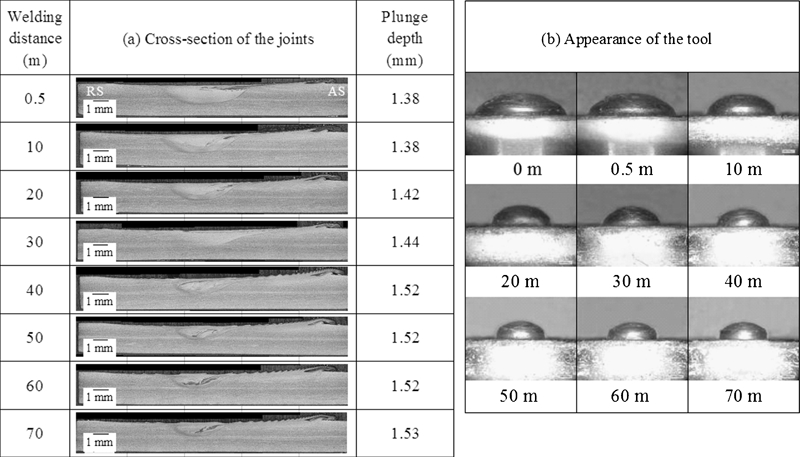
Cross-sections of joints and appearance of tool after stir in plate FSW at 22·2 rev s−1 and 5·3 mm s−1
Conclusions
The FSW of 304 stainless steel using an Ir based alloy tool was carried out without shielding gas, and the appropriate welding conditions, joint properties and tool life were investigated. The results of this study are as follows.
During the FSW using a position control machine, the appropriate welding conditions of the 304 stainless steel using an Ir based alloy tool are less than the travelling speed of 8·3 mm s−1 and less than the revolution pitch of 0·3 mm rev−1.
The strength of the joints obtained under appropriate welding conditions is similar to that of the base metal.
When the rotation pitch is ∼0·3, the degree of tool wear of the Ir based alloy tool with 1·4 mm probe height, which was used for the FSW of 304 stainless steel plate with 2 mm thickness, was less than or equal to that of the PCBN tool with 2 mm probe height, which was used for the FSW of 304 stainless steel plate with 9 mm thickness.
The Ir based alloy tool with 1·4 mm probe height enabled the FSW of austenitic stainless steel over a 75 m distance with increasing plunge depth, and the probe was not fractured.
Footnotes
Acknowledgements
One of the authors (HF) would like to thank the financial supports from the Priority Assistance for the Formation of Worldwide Renowned Centers of Research – The Global COE Program (project: Center of Excellence for Advanced Structural and Functional Materials Design), a Grant-in-Aid from the Ministry of Education, Culture, Sports, Science and Technology (MEXT), Japan, and the Japan Science and Technology Agency (JST) under Collaborative Research Based on Industrial Demand ‘Heterogeneous Structure Control: Towards Innovative Development of Metallic Structural Materials’.