
Abstract
Joining of an aluminium alloy to a magnesium alloy (AA 6082-T6 to AZ31) has been carried out by linear friction welding. The joining of this material combination is of particular significance for automotive components. Results show that welds with reasonable strength (comparable to the yield strength of the parent materials in O temper) can be produced. Weld microstructures were characterised by backscattered scanning electron microscopy, hardness testing and laboratory based X-ray diffraction. A particular emphasis was placed on determining the effects of welding parameters on the relative amounts of detrimental intermetallic phase at the weld line.
Introduction
The welding of aluminium to magnesium is considered to be very challenging regardless of the welding process used. The principal difficulty when joining these materials is the formation of brittle intermetallic phases and eutectic structures at the weld interface, which degrade joint strength.1 Another factor is that the eutectic reactions in the aluminium–magnesium system take place at very low temperatures (437 and 450°C; Fig. 1) relative to the melting temperatures of the bulk material2 (∼600°C, dependant on the alloy). This makes the formation of these intermetallics practically unavoidable when using almost any joining process. The task is then to limit the amount of intermetallic formed in order to achieve good weld strength.
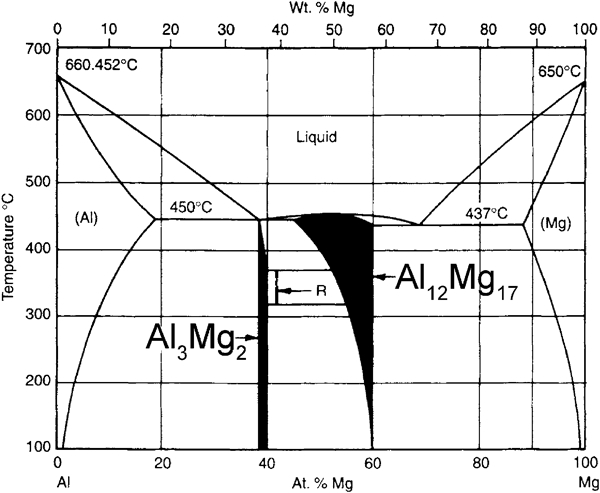
Al–Mg equilibrium phase diagram:3 intermetallic phases form at low temperatures relative to melting (∼600°C for both materials) and hot working (AZ31, 230–425°C; and AA 6082, ∼450°C) temperatures of two parent materials; they are therefore hard to avoid
This present work discusses the linear friction welding (LFW)4, 5 of aluminium to magnesium, which has potential significance for automotive applications. AA 6082-T6 (aluminium) and AZ31 (magnesium) were used, which are typical grades used by the automotive industry. The aims of this work were to demonstrate the feasibility of joining these materials and to analyse the effects of welding parameters on the weld microstructures.
The solid state friction welding processes, of which LFW is a subset, are potentially attractive for the joining of aluminium to magnesium as they allow low welding temperatures relative to fusion welding processes. Therefore, the likelihood and amount of intermetallic phase formation should be reduced when using these processes, potentially producing high weld strength. Such solid state welding processes also allow the avoidance or at least minimisation of problems associated with differences in melting temperature and thermal expansion mismatches when joining dissimilar metals. Linear friction welding may be particularly suitable for the welding of these materials as it has been demonstrated that the time at high temperature during welding can be controlled, to some extent, by careful choice of welding parameters.6 Therefore, the LFW process has the potential for limiting the tendency of intermetallic formation using welding parameters which allow limited time at high temperature and hence producing welds with improved mechanical performance and structural integrity. However, for an integral weld, the interface temperature would equally need to be high enough to allow adequate material plasticity. Welds may consequently need to be produced at temperature conditions which satisfy both the requirements for adequate plasticity and the limited intermetallic formation.
There have been a number of studies reporting the welding of aluminium to magnesium using various different welding processes, including friction stir welding (e.g. Firouzdor and Kou2), laser welding (e.g. Borrisutthekul et al. 7), diffusion bonding (e.g. Liu et al. 8), arc welding (e.g. Zhang and Song9) and explosive welding (e.g. Yan et al. 10). In the majority of these studies, weld strength has been very poor because of the large scale formation of intermetallic phases. However, more recently, there have been a number of studies which have demonstrated that welds with reasonable strength can be produced. Among these is the work of Zettler,11 which demonstrated that the weld tensile strength just less than those of the parent materials (189 MPa; ∼75% of base Mg alloy strength12) could be produced using friction stir welding when the weld set-up was optimised. Similarly, encouraging results have been seen when using a hybrid between metal inert gas welding and adhesive bonding13 (highest lap joint shear strength of 130 MPa achieved; ∼90% of base Mg alloy shear strength12) and hybrid laser/friction stir welding with a pure nickel interlayer14 (highest tensile strength of 169 MPa; ∼65% of base Mg alloy strength12). It is important to note that the highest tensile strength achieved for the friction stir welding of AZ31–AZ31 was ∼200 MPa15 (∼80% of base material strength12). Therefore, some of the reported strengths are close to the strength of magnesium similar welds. It should also be noted that high strength aluminium–magnesium welds were reported for thin section welds 2,11 1·513 and 4 mm14), and it may be more difficult to achieve adequate weld quality in thicker section specimens (the AZ31–AZ31 welds as reported by Johnson and Threadgill15 were from 6 mm thick plates). Thin plates would be expected to cool significantly faster than thick plates, and this may have an impact on intermetallic formation, which may in turn have an impact on weld strength.
Experimental
Attempts were made to weld samples of geometry 50×12×40 mm, with a weld interface of 12×50 mm. AA6082-T6 [Al–0·6Mg–1·0Si–0·5Mn–0·2Fe (wt-%)] and AZ31 [Mg–2·4Al–0·3Mn–1·2Zn (wt-%)] alloys were used for welding trials. Samples were machined to the correct dimensions using a manual milling machine to a tolerance of ±0·2 mm. Welds were produced on a hydraulic type LFW machine4 based at TWI Ltd, Cambridge, UK.
The magnesium sample was reciprocated in the 12 mm dimension, while the aluminium sample was held stationary. Process parameters that were varied in this study were friction and forge pressures, frequency of oscillation and amplitude of oscillation. A burn-off distance (distance that parts are allowed to shorten during the friction stage) of 2 mm was used for all the welds (please see Refs. 4 and 5 for detailed definitions of these parameters).
Weld mechanical properties were characterised by tensile testing, with tests conducted in accordance with BSEN 1002-1:2001. Micro-Vickers hardness traces were completed across a number of welds in order to determine trends with different welding parameters. In order to obtain close spacing between hardness indents, a diagonal path was utilised. The distance between indents was always at least three times the diagonal length of the indent, and all hardness indents were made in the middle two-thirds of the weld.
Weld microstructures were characterised from analysis of backscattered scanning electron microscopy images and laboratory based X-ray diffraction. X-ray diffraction was used to quantify the relative amounts of intermetallic phases in welds produced using different welding parameters in order to allow correlation with mechanical property (tensile strength) data. The fracture surfaces of previously tensile tested samples were studied using Co Kα radiation, with a 2θ step size of 0·05° and a counting time of 40 s. A Philips Xpert-1 machine was used with a Bragg–Brentano set-up.
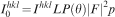
Phase fractions were determined from relative absolute integrated intensities (Ihkl), which can be calculated from diffraction integrated intensities (
 ) correcting for:
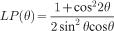
Lorentz polarisation:
multiplicities (p)
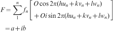
structure factor (|F|2)
of the individual peaks
Results and discussion
Macro- and microstructure
A total of 28 welds were produced in the present study (Table 1). In the majority of cases, the welds exhibited some level of adhesion; however, in a number of cases, samples were not joined at all or fractured on removal from the machine. In cases where there had been some adhesion, the welds appeared macroscopically satisfactory (Fig. 2), with ample flash coming from the magnesium half of the weld. Very little, if any, flash expulsion took place from the aluminium half of the weld owing to its significantly higher strength at high temperature, but in the majority of cases, there had been some deformation of aluminium because of the high applied pressures used during welding.
Aluminium to magnesium weld (magnesium top and aluminium bottom): almost all of flash comes from magnesium half of weld because of its lower strength at high temperature
Welding parameters and mechanical testing results for LFW of aluminium to magnesium. Two tensile specimens were taken from each weld that was tested. ‘No weld’ indicates that samples were not joined on removal from welding machine. ‘Fail’ in tensile strength column indicates that weld failed during preparation of tensile specimen
Examination of the weld microstructure showed that, in most cases, there was intimate contact between the two materials with no obvious microstructural defects such as voids or a lack of bonding (Fig. 3a). However, at certain welding parameters, there was some lacking of bonding at the weld interface (Fig. 3b). No obvious evidence of large layers of intermetallic and low melting point eutectic phases was found from the images. However, it was clear from the images that there was significant movement of the magnesium material and to a lesser, but still significant, extent the aluminium during welding (Fig. 3c).
Backscattered SEM images of aluminium–magnesium welds: there appear to be fine stacked layers of aluminium and magnesium or layers rich in aluminium and rich in magnesium at weld interface
Effects of welding parameters on weld mechanical properties
All welds fractured cleanly across the weld interface during tensile testing, at failure stresses lower than those of either parent material. An ultimate tensile strength of 140 MPa was recorded for one weld, which is just less than the yield strength of the parent magnesium in O temper (∼150 MPa). This strength compares reasonably well with those presented in public domain literature (as discussed in the section on ‘Introduction’ of this report) and compares well with the strength of AZ31 similar friction stir welds (ultimate tensile strength of ∼200 MPa15), particularly when the additional complications of producing dissimilar welds are taken into account.
From consideration of the results in Table 1, it is evident that the repeatability when welding these materials was poor. This is signified by the fact that a weld was produced for S21, while for S22 and S23, the samples were not joined on removal from the machine, despite using the same welding parameters (Table 1). The weld strength for S26 was also much lower than for S12, again despite using the same welding parameters.
The samples for the current study were produced using a manual milling machine. There was no particular emphasis on controlling the surface finish of welding faces, although it could potentially have an impact on the weld properties if the surfaces are very rough.18 Care was taken, however, to obtain a visually smooth and flat surface and to use sharp cutting tips when machining. It has been demonstrated that adequate repeatability can be achieved when welding aluminium to copper using these procedures.19 Indeed, very good repeatability has been demonstrated even when using LFW with saw cut welding faces (when welding 316L stainless steel6 and C–Mn steel20). Saw cutting would provide a significantly poorer and more variable surface finish than milling. It is therefore surprising that repeatability was poor for this combination despite similar or better preparation conditions being used than those often used when using LFW with other materials or dissimilar combinations. Perhaps with the present, very challenging, material combination, even relatively minor changes in welding preparation would have a major impact on weld mechanical properties as the range of conditions for achieving welds with any level of strength is very narrow. A particularly stringent set of welding procedures may therefore be needed to allow adequate repeatability for this combination if welding for production applications.
The lack of repeatability could also be related to the fact that intermetallics may not be uniformly distributed across the whole of the weld interface, and differences in intermetallic layer thickness may exist in different regions of the weld. Certainly, the more general microstructure in aluminium to magnesium welds can be different in different regions, and the stacked microstructure seen in Fig. 3c does not exist across the whole weld interface of the imaged weld (S8). Therefore, it is reasonable to suggest that the level of intermetallic phases may be different in certain regions of the weld, which could affect repeatability.
Tensile strengths taken from the same weld were also sometimes inconsistent, which is signified by the fact that one of the tensile specimens from S15 failed during preparation while the other had a reasonable strength. Similarly, for S20 and S28, the differences in strength from samples taken from the same weld were high. It is not clear at present why these differences in strength occur; however, it could be related to variations in intermetallic content in different regions of the weld, as mentioned above.
While there were issues with repeatability in this study, some trends in weld strength can be suggested. Figure 4a plots the weld tensile strength against the applied friction and forge pressure. Although there is a lot of scatter, the figure suggests that high applied friction and forge pressures can produce welds with increased tensile strength. The trend suggests that applied pressures above 133 MPa, which was the maximum used in this study, may improve strengths further. There appears to be a critical applied pressure threshold that needs to be exceeded to produce welds with any level of strength, and welds were not produced when applied pressures of <100 MPa were used. This can be seen on comparison of S2 (applied friction pressure of 100 MPa) with S7 (applied friction pressure of 66 MPa; otherwise, the same parameters as S2); S7 was produced using a lower friction pressure and was not joined on removal from the LFW machine, while S2 was at least joined and visually sound. A higher applied forge pressure was used for S7, relative to S2, but this should aid the consolidation and strength of the weld rather than hinder it.
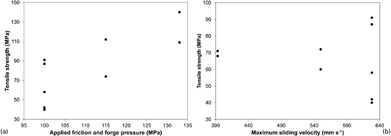
a effects of applied friction and forge pressure on weld tensile strength [frequency, 50 Hz; amplitude, 2 mm; burn-off distance, 2 mm; S15_Specimen1 (100 MPa applied pressure), which failed during preparation of the specimen, is not included in figure] and b effects of maximum sliding velocity on maximum recorded weld tensile strength (friction and forge pressure, 100 MPa; burn-off distance, 2 mm)
It has been shown previously, through studies on the friction stir welding of aluminium to magnesium,1 that the heat input condition is a key factor governing the strength of welds, and high weld strength is achieved at low heat input (low temperature or low time at temperature) conditions. This is because intermetallics, which are formed in large quantities at high temperature, have a significant effect on weld failure and strength.1 In LFW, the use of a high applied pressure is thought to reduce the time at high temperature that material close to the weld interface is exposed.21, 22 Therefore, high weld strength also seems to be achieved at low time at temperature conditions for the LFW of aluminium to magnesium, similar to the trends seen in the work on friction stir welding.
From the results, it seems to be difficult to produce welds at very high sliding velocities, and a weld could not be produced for S28 (max sliding velocity of 785 mm s−1). This is possibly because of the high heat input at very high sliding velocities. A trend between weld strength and sliding velocity could not be identified because of the large scatter in tensile strength results (Fig. 4b). Similarly, it is hard to identify trends in strength with just amplitude and frequency individually because of the large scatter and the small number of tensile tested samples.
Finally, it appears to be difficult to achieve welds with any level of adhesion at very high amplitudes regardless of the overall sliding velocity. A total of six samples were produced with an amplitude of 3 mm, and all aside from one were not welded on removal from the LFW machine. At high amplitudes, there is a large exposure of the welding face to the surrounding environment, which may potentially allow greater oxidation and therefore poor welds. Off centre loading is also more significant at high amplitudes, which may also affect the welding process.
As the applied friction and forge pressures had the greatest impact on weld strength, it was determined that changes in hardness traces in welds produced using low, mid and high friction and forge pressures (S16 applied pressure of 100 MPa, S19 of 115 MPa and S24 of 133 MPa) should be analysed. From Fig. 5, it can be seen that there was a slight increase in the hardness of magnesium, relative to the parent, close to the weld line. This could be because of workhardening or grain refinement at near weld line regions, both of which are common during LFW. In contrast, the aluminium alloy displayed a reduction in hardness close to the weld line. This is to be expected as the aluminium material in T6 (peak strength) condition was welded, which is likely to have softened during welding because of the overaging of hardening particles. With welds exhibiting a hardness trace as in Fig. 5, and for welds without microstructural defects, it would be expected that the welds fail, during tensile testing, in the low hardness and strength parent magnesium. However, this is clearly not the case, which suggests that intermetallic layers at the weld interface are playing a dominant role in the failure of welds.
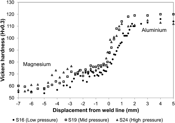
Hardness traces across aluminium–magnesium welds S16 (low applied pressure, 100 MPa), S19 (mid applied pressure, 115 MPa) and S24 (high applied pressure, 133 MPa)
Effects of welding parameters on intermetallic phase fractions
X-ray diffraction analyses were undertaken on tensile fracture surfaces of aluminium–magnesium welds. The advantage of using this technique is that the facture surfaces of samples with known levels of tensile strength can be directly analysed. This is important as the lack of repeatability discussed previously may be related to slight changes in welding conditions and subsequently microstructure. A direct analysis of fracture surfaces therefore avoids issues with repeatability. Peaks corresponding to Mg, Al and Al12Mg17 were detected on the magnesium half of the welds, while on the aluminium half, peaks corresponding to Al, Mg, Al12Mg17 and Al3Mg2 could be detected (Fig. 6).
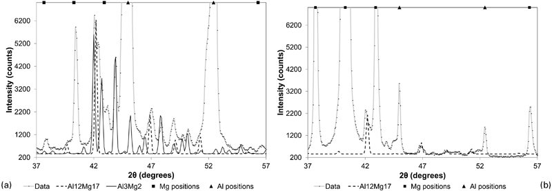
Extracts of X-ray diffraction traces from a aluminium half of weld S12 and b magnesium half of S12. Positions of aluminium and magnesium peaks are indicated, and diffraction pattern is overlaid with ideal diffraction patterns for Al12Mg17 and Al3Mg2: Pattern consists of mainly aluminium in a and magnesium in b; Small peaks corresponding to Al12Mg17 and Al3Mg2 were detected on aluminium half of weld, while small peaks corresponding to Al12Mg17 could be detected on magnesium half; in each case, there were some small peaks which were unidentifiable
Attempts were made to quantify the relative amounts of intermetallic phases in welds produced using different welding parameters. This was performed in order to allow correlation with weld strength. As the applied pressure had the greatest impact on weld strength, the tensile fracture surfaces of welds produced at low, mid and high friction and forge pressures (S12_Specimen1, 100 MPa applied pressure; S20_1, 115 MPa; S28_2, 133 MPa; Table 1) were analysed using X-ray diffraction. Two tensile specimens were taken from each of these welds, and the specimen that failed at higher load was analysed. Only the aluminium fracture surface was examined, as this side of the specimen had a significantly greater weight fraction of intermetallic phases compared to the magnesium side.
Results from the analyses are shown in Fig. 7. There is a general trend towards lower intermetallic weight fractions when high pressures are used, and the data suggest that there is limited intermetallic formation in high strength welds, which are produced at high pressure. However, the weight fractions from welds produced at 115 MPa (S20) and 133 MPa (S28) applied pressure were quite similar even though there were significant differences in the tensile strengths of these samples (Table 1).
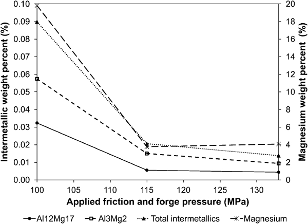
Effects of applied friction and forge pressure on weight per cent of intermetallic phases and magnesium on tensile fracture surface of aluminium half of aluminium–magnesium welds
It is important to note that a phase fraction analysis with very complex diffraction traces, as presented in Fig. 6, is difficult. The fact that there is a large number of overlapping peaks means that it is sometimes difficult to assign particular peaks to particular phases. Low intensity peaks from intermetallic phases, which are present in very small quantities, may also become indistinguishable from the background. These factors may have caused inaccuracies in phase fraction analysis, leading to the very low weight fractions of intermetallics seen in Fig. 7. However, for all samples, the peaks were located at the same set of 2θ values, and so peaks at particular 2θ values could be assigned to the same phase for each sample. The relative phase fractions, which this study is particularly interested in, would therefore not be affected by the discussed possible sources of inaccuracies.
It is also interesting that there was a significant reduction in magnesium weight fraction on the aluminium half of the weld at high pressure (Fig. 7). This is despite weld strength significantly improving when high pressure was used. This is not altogether unexpected as experience has shown that low applied pressures tend to give better adhesion and weldability conditions when friction welding dissimilar materials.18 For the welding of this combination, however, the weld strength seems to be completely dominated by intermetallic weight fraction. Therefore, weld strength can be high even at poor weldability conditions if the intermetallic weight fraction is limited. Given this observation, the attainment of weld strength comparable to the strength of the parent materials may be almost impossible for this material combination as there needs to be a compromise between low pressure conditions, which give good adhesion, and high pressure conditions, which give low intermetallic formation.
Conclusions
The current report presented work on the LFW of aluminium to magnesium. The welding of this combination proved viable with a maximum tensile strength of just less than the yield strengths of the parent materials in O temper reported. The maximum recorded strength compares reasonably well with those previously reported in public domain literature and also compares well with the strength of AZ31 similar friction stir welds.
Trends between weld strength and friction and forge pressures showed that welds with high strength can be produced with high applied pressures. The trend also suggested that the use of applied pressures greater than those used in this work may improve strength further. Certainly, the attainment of weld strength similar to those of magnesium–magnesium welds seems viable with further parameter refinements, although welds with mechanical properties equal to those of the parent magnesium may be much more difficult to achieve.
The intermetallic phases Al12Mg17 and Al3Mg2 were detected at the weld interface, and these phases seemed to be the main reason for the welds having poorer mechanical properties than the base materials. The intermetallic volume fraction decreases with increasing weld pressures, but the intermetallics were not eradicated completely even at high pressure conditions. Even small weight fractions of these phases seem to compromise mechanical properties.
Footnotes
Acknowledgements
This work was funded by TWI as part of exploratory projects, with funding also provided by the EPSRC. The authors would also like to thank Judith Shackleton for help with X-ray diffraction.