
Abstract
Adaptive remeshing technique based finite element model of friction stir welding was used for the investigation of tool forces in the welding processes. Results indicate that the maximum tool forces occur at the initial time in the translational stage. In the tool forces in the three directions, the axial force is the maximum. The tool force in the direction perpendicular to the welding line is the minimum. The tool forces in the three directions are all increased with the increase in transverse speed and decreased with the increase in angular velocity.
Introduction
Friction stir welding (FSW) was invented by TWI1 in 1991 as a solid state and hot shear joining technique.2 It can be applied to the joining of hard to weld materials with low defects and low distortions, such as aluminium alloys, magnesium alloys, etc.3, 4
The modelling of heat transfer, fluid flow and mass transfer can provide detailed insight into the welding processes.5 Different models have been developed for the investigations on heat transfer,6– 9 fluid flow and mass transfer,10– 14 residual state15– 19 and even microstructural changes20, 21 in FSW. The heat in FSW is generated by both frictional and plastic energy dissipations. More than 50% total energy can be transferred to the welding plates and ∼85% energy can be converted to frictional heat in FSW of AA 2024-T3.11 The welding tool can also be heated in FSW.
The rotating tool is a critical component to the success of FSW.22 The design of the welding tool can affect the quality of the obtained friction stir weld and the tool forces in the FSW process. Buffa et al. 23 compared two tools with cylindrical and conical pins by finite element method. The selection of tool materials and tool geometries can have obvious influences on FSW.24– 26 In the translational stage of FSW, the forces on the welding tool and the heat flow into the welding tool decide the fatigue life of the welding tool. Dicherson et al. 27 investigated the heat flow into FSW tools. Balasubramanian et al. 28 reported the process forces on the welding tool in FSW of AA 6061 and F357. It is found that the net resistance offered during the friction stir processing of wrought aluminium alloys is higher than that of the cast alloys.
Detailed studies of the tool forces on the welding tool are very important for the development of FSW. Therefore, an adaptive remeshing technique based finite element model of FSW is proposed for the investigation of the forces in the FSW process. Compared with the ALE model, penetration depth in the axial direction instead of the axial load can be used for the controlling of the axial movement of the welding tool in the adaptive remeshing model with consideration of the tilt angle.
Model description
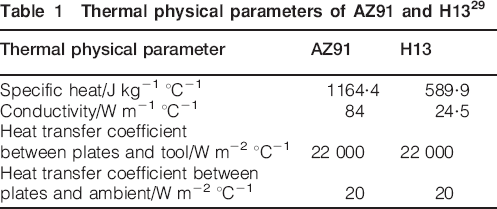
The dimensions of the welding plates for FSW are 80×40×5 mm. The initial mesh size for the welding plates is 0·75 mm in and near the welding region. In the other regions in the welding plates, the mesh size is taken as 1·5–3 mm. The total finite element model of the welding plates consists of 4648 nodes and 18 611 tetrahedral elements in the initial state. The mesh size of the welding tool is 0·75–3 mm. The welding tool consists of 1618 nodes and 6541 elements, as shown in Fig. 1. The radii of the shoulder and the pin are 7·5 and 2 mm respectively. The material of the welding plates is AZ91 magnesium alloy, and the material of the welding tool is H13 steel. The physical parameters of the materials of the welding tool and plates are listed in Table 1.
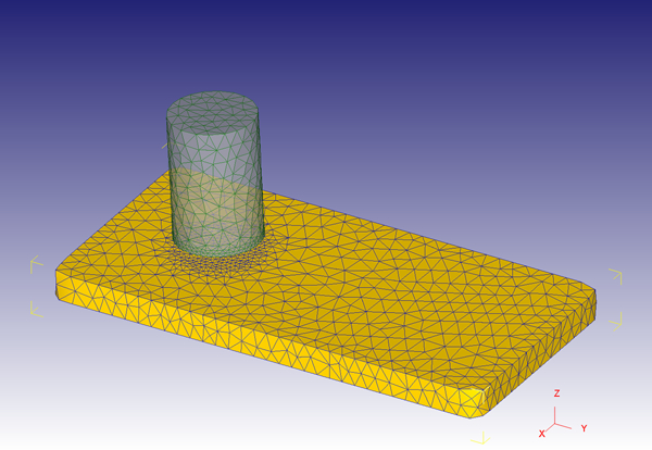
Initial meshing of FSW model
Thermal physical parameters of AZ91 and H1329
Arrhenius equation was used for the description of the flow stress of the AZ91 magnesium alloy29
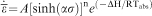
 is the equivalent stress and
 is the equivalent strain rate

The Levy–Mises flow rule is used to relate stress and strain tensor31

Two processes are considered in the FSW process, i.e. the plunge period and the welding stage. In the plunge period, the welding pin is inserted into the butt of the two plates with a velocity of 1 mm s−1. The tilt angle of the tool is 3°. The penetration depth is 0·3 mm. In the welding stage, the welding tool is moved with a constant translational velocity. The boundaries of the plate are set to be room temperature.
Shear model is used for the definition of the contact between the welding tool and the plates31

To control the mesh distortions caused by the movements of the welding tool, adaptive remeshing technique is used. The fraction is selected to be 0·7 for the programme to conduct a check on each surface edge that has a contact node on each end. The distance from the middle of the edge to the welding tool surface is then calculated and divided by the original length of the edge. If the ratio exceeds the magnitude of the specified value (0·7), remeshing will be triggered.
The balance of the body forces and surface tractions is expressed as
The temperature field can be obtained by solving the following equation

Results and discussion
The temperature distributions are shown in Fig. 2. With the variation of the angular velocity from 900 to 1200 rev min−1, the maximum temperature on the joined plate is increased from 450 to 465°C. This variation is fitted well with the observations from both numerical simulation13 and experiment.33 When the translational velocity is increased from 40 to 60 mm min−1, the maximum welding temperature is increased from 450 to 456°C.
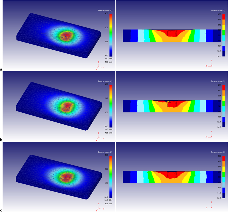
Temperature fields
To show the validity of the current model, the obtained temperature field in 900 rev min−1 and 40 mm min−1 was compared with the experimental test,29 as shown in Fig. 3. The temperature history obtained from the current model is fitted well with the experimental data.
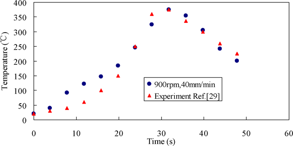
Comparison of temperature derived from simulation with experimental test
The maximum effective strain is 95 in 900 rev min−1. When the angular velocity is increased to 1200 rev min−1, the region of high effective strain is decreased in the current case, as shown in Fig. 4. When the translational velocity is increased, the maximum effective strain is decreased.
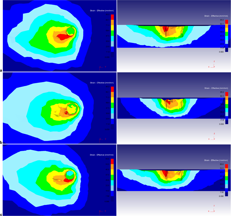
Effective strain
Different to the ALE model, the heat transfer on the welding tool is calculated in the current adaptive remeshing model. The temperature distributions on the welding tool in different cases are shown in Fig. 5. In the case of 900 rev min−1 and 40 mm min−1, the maximum temperature on the welding tool is 437°C. When the angular velocity is increased to 1200°C, the maximum temperature is increased to 451°C. When the transverse velocity is increased to 60 mm min−1, the maximum temperature is increased to 445°C.
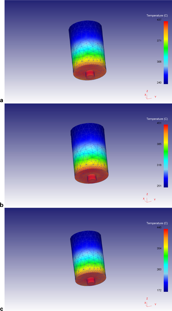
Temperature distributions on welding tool
In the case of 900 rev min−1 and 40 mm min−1, the predicted tool force in the axial direction can be compared with the experimental test,29 as shown in Fig. 6. The comparison shows the validity of the current model for the prediction of tool forces.
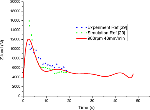
Comparison of tool force in axial direction with experimental test
When the angular and transverse speeds are changed, the variations of the forces in the three directions are shown in Figs. 7–9. It can be seen that the forces in the three directions are increased with the increase in translational speed and decreased with the increase in angular velocity. Among the three force components, the axial force is the maximum. This force is one of the main factors for the determination of frictional force on the shoulder and pin tip surfaces. The tool force in the axial direction is increased in the plunge period and reaches its maximum at the initial time of the translational stage. When the tool keeps moving along the welding line, the axial force is decreased. The force in the direction perpendicular to the welding line is the minimum. This force is caused by the non-uniform material flow shown in Ref. 13.
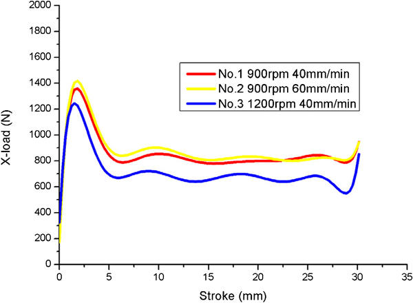
Tool force in direction perpendicular to welding line
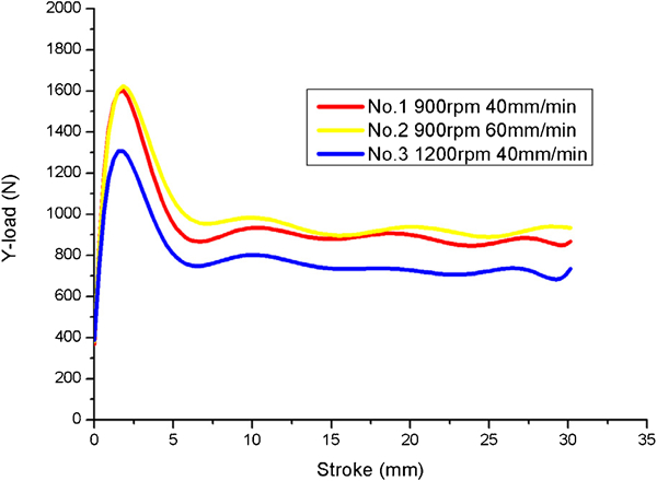
Tool force in direction along welding line
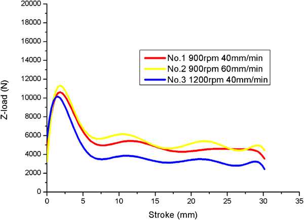
Tool force along axial direction of tool
Conclusions
The tool forces in the three directions are increased with the increase in transverse speed and decreased with the increase in angular velocity.
In the tool forces in the three directions, the axial force is the maximum. The tool force in the direction perpendicular to the welding line is the minimum. This force is caused by the non-uniform material flow.
The maximum temperatures on the welding plate and on the tool can be both increased with the increase in angular velocity of the welding tool.
Footnotes
Acknowledgements
This work was supported by the National Natural Science Foundation of China (grant no. 11172057) and the National Key Basic Research Special Foundation of China (grant no. 2011CB013401).