
Abstract
Friction stir welding has been successfully used to weld the dissimilar metals. A few investigations have been carried out on the friction stir lap welding of Al to Cu, but the basic issue of how the position of the metals would affect the joint strength is still not resolved. In the present study, the 7070 Al and the commercially pure copper are lap joined using friction stir lap welding technology. Two test cases are considered. The distinction refers to the position of Al with respect to Cu. Microstructural analyses are carried out to gain intermetallic compounds and some microcracks. The effect of position of materials on the heat generation is investigated and justified through the temperature measurements. Mechanical properties of each sample are characterized using both shear and hardness tests. The results reveal that the maximum fracture load of the joint is obtained when Al is placed on the top of Cu.
Introduction
The development of sound joints between dissimilar materials is of great importance in many emerging applications including chemical, nuclear, aerospace, transportation, power generation and electronics industries.1 Joining dissimilar materials by the conventional fusion welding is difficult for two reasons: (i) poor weldability arises due to the different chemical, mechanical and thermal properties of the welded materials; (ii) hard and brittle intermetallic compounds (IMCs) are usually formed at the weld interface. Friction stir welding (FSW) is a technique invented in 1991 by the Welding Institute2 for joining aluminium alloys. This technique results in lower distortion and higher joint strength in comparison to the other techniques and is capable of joining all aluminium alloys including dissimilar ones.3 It uses a non-consumable rotating tool to generate frictional heat and deformation at the welding zone leading to the formation of a joint while the materials are still in the solid state.4 At the joint, the material is frictionally heated to temperatures at which it is easily plasticised. Recently, some attempts have been made to join the dissimilar materials such as dissimilar Al alloys,4– 6 aluminium to steel,7– 9 aluminium to magnesium10, 11 and magnesium to steel.12– 14 To meet the requirements dictated by the electronic and power generation industries, a few preliminary studies have also been reported on the FSW of aluminium to copper.15– 18 Due to the different chemical, mechanical and thermal properties of materials, a dissimilar materials joining process offers significant challenging problems. Ouyang et al. 15 claimed that the direct FSW of 6061 aluminium alloy to copper was difficult due to the brittle nature of the IMCs formed in the weld nugget. Recently, Elrefaey et al. 16 studied the feasibility of FSW of dissimilar lap joints of an aluminium sheet to a copper one. The level of bond strength was quite low in their investigation and the relationship between the fracture location and the microstructure suggested that IMCs formed in the interfacial region were responsible for the low strength of the joints. Abdollah-zade et al. 17 observed a black area consisting of IMCs of Al4Cu9, AlCu and Al2Cu near the Al/Cu interface, where the crack could be initiated and propagated preferentially during the tensile test. As far as the authors know, however, no systematic attempts have been made to characterise the effects of dissimilar sheets positioning on the properties of the joint formed via FSW. The present study aims to study experimentally the feasibility of friction stir lap welding of Al to Cu as well as to evaluate the effect of the position of Al and Cu with respect to each other on the properties of the resultant joint.
Experimental
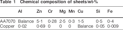
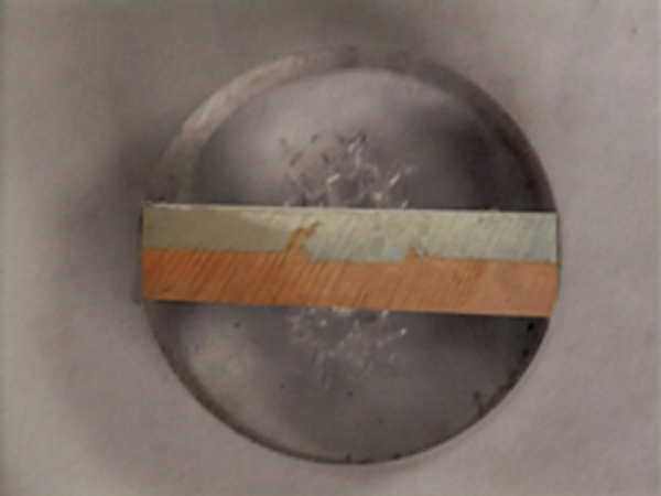
Two dissimilar rolled sheets were used in the FSW process carried out in the present work: a 7070 aluminium alloy sheet under annealing condition and a commercially pure copper sheet. The sheets were 2 mm thick and their chemical compositions are given in Table 1. The welding tool used in the FSW process was made of 2436 steel alloy, which encompasses a concave shoulder with a diameter of 17·5 mm and a non-threaded cylindrical pin with length and diameter of 3·5 and 5 mm, respectively (see Fig. 1). The tilt angle of the rotating tool with respect to the z axis of the milling machine was about 2 degrees. The workpiece was tightly clamped down using four steel screws (see Fig. 2). An infrared thermometer (see Fig. 3) was used to monitor the changes in joint temperature during the welding process. The temperature measurement process is needed for the purpose of thermal analysis of the joint. As shown in Fig. 4, the thermometer was fixed to the table, close to the backing plate and it could move with the table's feeding speed. It may be noted that, the temperature measured here is the temperature of the point A (see Fig. 4) rather than point B as considered by Tang et al. 19 However, the trend of the temperature variations diagram for point A is the same as the case when point B was considered, although the temperature of point A always falls below those of point B. The lap joining process was performed via FSW at the tool rotational speeds of 700, 900, 1120 and 1400 rev min−1 and the traverse speeds of 25, 40 and 70 mm min−1. The other parameters such as the tool geometry were kept fixed. Two cases regarding the position of Al with respect to Cu were considered. In the first case, denoted as Case I in the rest of the paper, the Al sheet was placed over the Cu sheet. In the second case denoted as Case II, the positions of the sheets in Case I were reversed. It is worth mentioning that in both cases the upper sheet was in touch with the shoulder of the welding tool during the FSW process. Figure 3 shows two typical lap welded joints associated with Case I (Fig. 5a) and Case II (Fig. 5b).
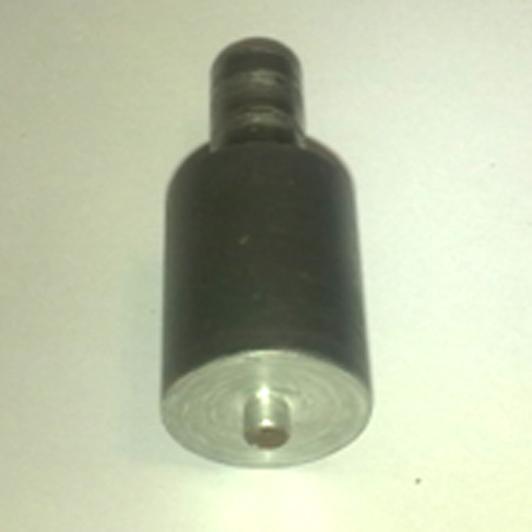
Welding tool used in FSW process
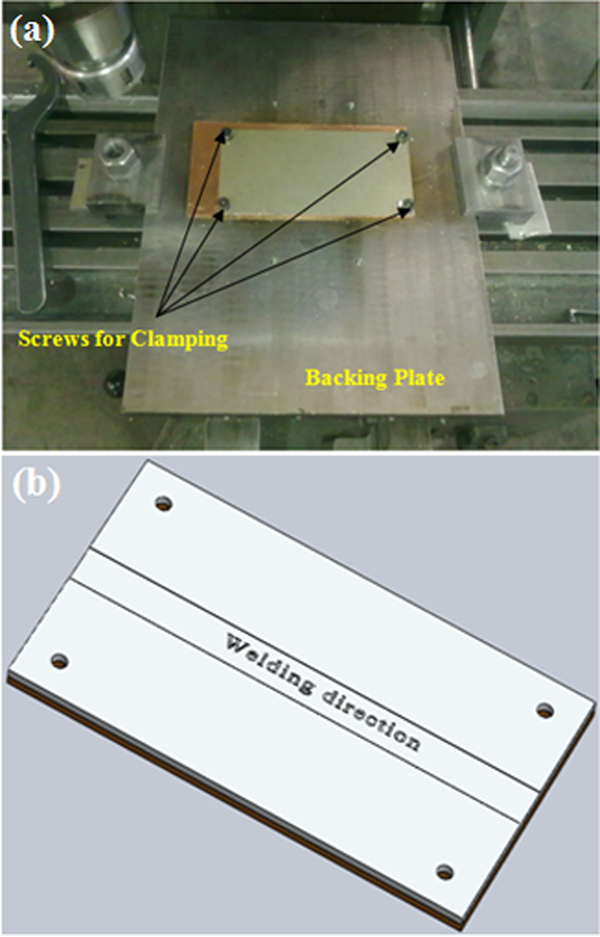
a experimental setup and b schematic representation of FSW sample

Infrared thermometer used in FSW process
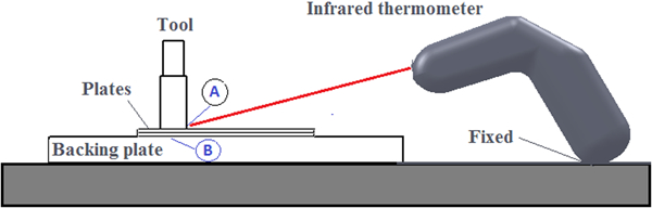
Schematic presentation of weld setup including thermometer
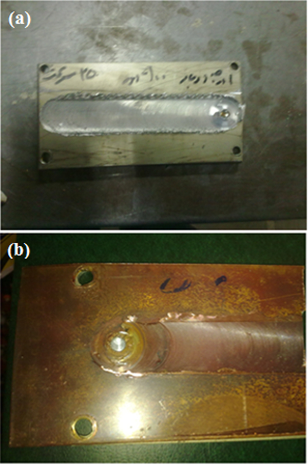
Typical samples of weld joints for a Case I and b Case II
Chemical composition of sheets/wt-%
For metallurgical analysis, the specimens were prepared using standard metallographic procedure according to ASTM E3-01. The chemical etching of aluminium alloy was performed using Keller's reagent (1 mL HF, 1·5 mL HCL, 2·5 mL HNO3 and 95 mL H2O) to reveal its microstructure and the copper was etched by means of a solution of 5 g FeCl3, 50 mL HCI and 100 mL H2O. Microstructures of the alloys are observed using an optical microscopy. A typical prepared sample is shown in Fig. 6.
Prepared sample of FSW joint
In order to characterise the mechanical properties of the joint such as lap shear fracture load (LSFL) in the two cases, a set of lap shear tests was carried out. In addition, the hardness of the welded samples was measured at different points along the welded zone and through the thickness by using Vickers microhardness tester. For this purpose, a load of 100 g was applied for 15 seconds. The dimensions of the prepared specimens employed in the lap shear tests are given in Fig. 7.
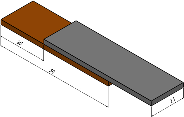
Dimensions of prepared specimens for lap shear test
Results and discussion
Microstructural analysis
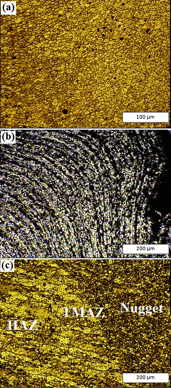
The micrographs of different areas of the Al–Cu joint for both Cases I and II are depicted in Figs. 8 11. Figures 8 and 9 show the microstructures in Case I associated with Al and Cu respectively. Also, the microstructures observed in Case II for Al and Cu are shown respectively in Figs. 10 and 11. According to the optical microscopic investigations and based on the microstructural characterisation of grains and precipitates carried out in the present work, three distinct zones have been identified in all of the welding samples in both the aluminium and copper sides: the stirred (nugget) zone, the thermomechanically affected zone (TMAZ) and the heat affected zone (HAZ). The weld forms a consolidated nugget with fine grains accompanied by a fully recrystallised material, which is surrounded by a TMAZ with a significantly different microstructure. Far enough away from the weld is an HAZ, beyond which the base metal remains unaffected.
Optical micrographs associated with Case I
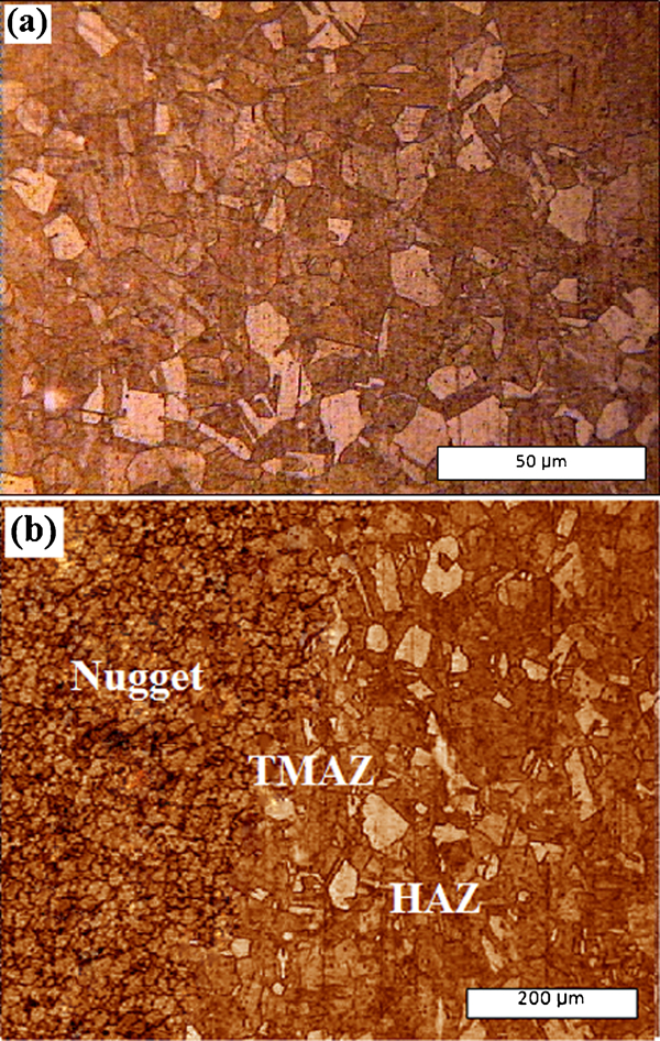
Optical micrographs associated with Case I
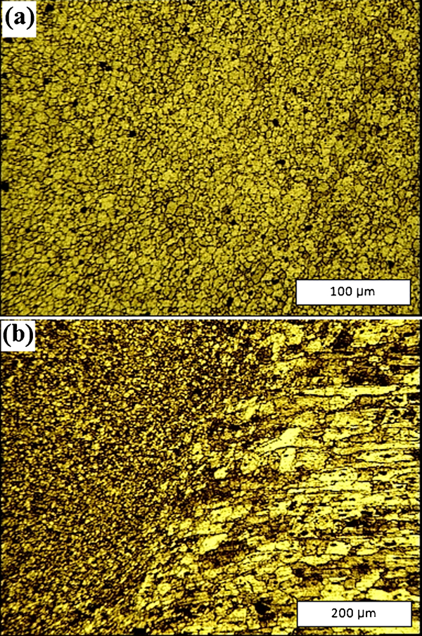
Optical micrographs associated with Case II
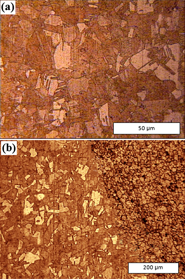
Optical micrographs associated with Case II
It is well accepted that the dynamic recrystallisation during the FSW process results in the generation of fine and equiaxed grains in the nugget zone, which can be attributed to the effect of rotating pin on the deformation and recrystallisation of the grains in the stir zone. The extent of the stirred zone decreases with increasing welding speed. This may be attributed to the lower heat input and the consequent lower peak temperature associated with the faster welding. In this zone, due to the friction between the shoulder and workpiece and to the plastic deformation of the material, the temperature increases to 0·6–0·9Tm,20, 21 where Tm is the melting temperature. The TMAZ is characterised by a highly deformed structure. This interface represents the salient difference between the structure of the base metal grains and structure of the grains obtained from the dynamical recrystallisation process (i.e. the nugget zone). A typical micrograph of TMAZ associated with Case I is shown in Fig. 8b. Although the TMAZ undergoes plastic deformation, it may not experience recrystallisation due mainly to the insufficient deformation strain. The parent metal elongated grains are deformed in an upward flowing pattern around the nugget zone (see Fig. 8b). This reveals that the grains in the TMAZ usually contain a high density of sub-boundaries22 and there exists an HAZ beyond the TMAZ. This zone experiences a thermal cycle, but does not undergo any plastic deformation.
Thermomechanical analyses
In general, the lap joints are loaded either by peel or in shear. In this study, the strength of the lap joints which are nominally loaded in overlap shear is examined. For all the tests carried out in the present work, the fracture points are located in the joint area. The diagram of the failure load versus rotational speed corresponding to the Cases I and II (see the section on ‘Experimental’) is depicted in Fig. 12a and b respectively. For each case three traverse speeds are tested and the related results are compared. The results shown in Fig. 12 can be interpreted as follows.
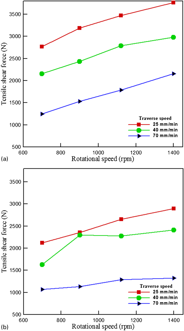
Lap shear fracture load (N) under various welding conditions
Effect of rotational and traverse speeds on failure load
The two important parameters affecting the FSW are the rotational speed and the traverse speed. The rotation of the tool leads to the mixing and stirring of materials around the rotational pin. In addition, the tool traverse displaces the stirred material from the front to the back of the pin. In FSW processes, higher rotational speeds or lower welding speeds lead to more heat input, which in turn provides better conditions for diffusion reaction of Al and Cu and consequently results in a thick weld zone (fine grained zone). Therefore, in both cases I and II the mechanical strength of the joint is improved with increasing the rotational speed or by reducing the traverse speed (see Fig. 12).
Effect of materials position on failure load
Figure 12 shows that under similar welding conditions the strength of the joint (failure load) in Case I is always higher in comparison with Case II. The peak temperature and cooling rate of the joint are two factors which are deemed to be more effective on the failure load among the other factors. The peak temperature depends strongly on the thermal conductivity of the upper sheet. The thermal conductivity k influences the heat concentration in the welding area. The friction between the shoulder and the surface of the upper sheet is the most important factor contributing the heat generation in the FSW process. Therefore, the higher thermal conductivity of the upper sheet, the faster distribution of the frictional heat through the sheet will take place in general. This prevents the heat to be concentrated in the welding zone and causes the produced joint to have (relatively) coarse mechanical properties. The values of thermal conductivity of copper and aluminium are 401 and 157 W m−1 K−1, respectively. So the thermal conductivity of copper is about two times larger than that of aluminium. In order to calculate the magnitude of the cooling rate in each case, the temperature is measured imediately after the joint is produced by the rotation of the tool.
Figure 13 depicts the variations of temperature versus time for the Cases I and II. It can be seen that in Case I the temperature of the joint approaches that of the environment relatively faster than in Case II, i.e. the cooling rate in Case I is relatively faster than in Case II. In addition, the peak temperature in Case I (472·2°C) is higher than that in Case II (373·1°C). This discrepancy in the peak temperature is attributed to the difference in the thermal conductivity of aluminium and copper, which are the upper sheets in Cases I and II respectively. As mentioned before (see the section on ‘Microstructural analysis’), when aluminium is placed over the copper sheet the produced joint has finer mechanical properties as compared to the case where copper is placed over the aluminium sheet. This is due to the more concentration of the heat in the weld area.
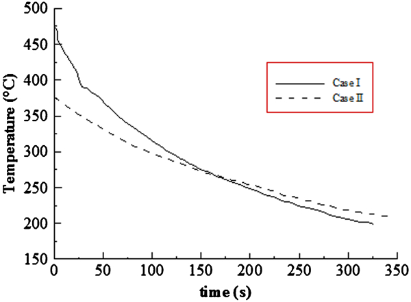
Temperature variations versus time for Al–Cu joint measured after FSW process is finished (welding conditions: 1400 rev min−1, 25 mm min−1)
Figure 14 shows the LSFL versus cooling rate, where the points denoted by Al and Cu refer to the Case I and Case II, respectively. Typical values of the cooling rate for Cases I and II at the rotational speed of 1400 rev min−1 are respectively 0·741 and 0·466°C s−1. It is clearly evident that for all the rotational speeds tested, Case I takes higher fracture load and cooling rate in comparison to Case II. This implies that increasing the cooling rate decreases the grains sizes, hence improving the mechanical properties of the joint, which is consistent with what found by Nelson et al.
21 The higher cooling rate for Case I may be interpreted through the following discussion. After the welding process is finished the heat transfer between the upper sheet and the surrounding air is the most dominent heat transfer mechanism. Therefore, the properties of the upper sheet, which is in direct contact with air is very important. The heat transfer analysis may be simplified through the use of lumped system analysis, which is an idialisation for transient heat conduction. It is generally accepted that lumped system analysis is applicable if Bi⩽0·1, where Bi is the Biot number defined as the ratio of the internal resistance of a body to heat conduction to its external resistance to heat convection, i.e.


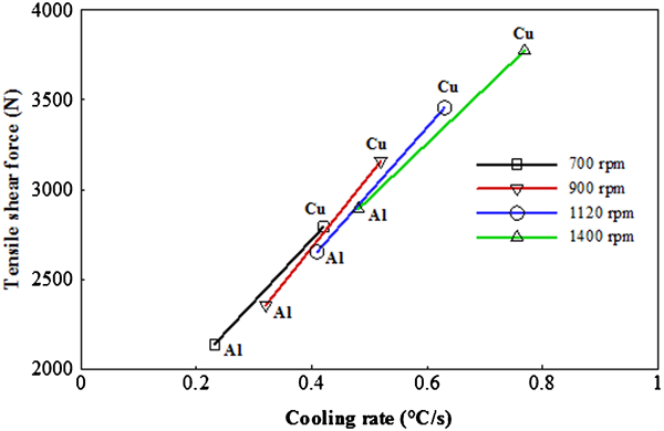
Fracture load versus cooling rate for different rotational speeds; points Al refer to Case I and points Cu refer to Case II (welding condition: 25 mm min−1)
Note that the value of h is such that the Bi number in both cases still remains much smaller than 0·1 and the lumped system analysis is applicable. Therefore, the transient heat transfer equation reduces to the following relation23
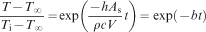
In this equation T and Ti are the instantaneous and initial temperatures of the body, respectively, T∞ is the temperature of the surrounding air, ρ is the density of the solid body, c is the specific heat of the body and t is time.
In equation (1), the difference Ti−T∞ is constant for each case, although it is bigger for Case I. In addition, the values of As, V and h are the same for both cases. Therefore, a smaller value of the multiplication ρc gives rise to a bigger value of exponent b in equation (1) and hence the temperature decreases more rapidly. It may be noted that the value of ρc for Al is bigger than that for Cu. Therefore, the temperature of the joint in Case I would decrease faster than in Case II.
Hardness
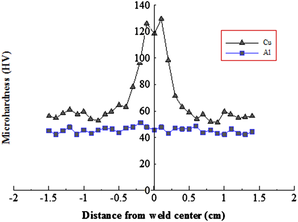
Figures 15 and 16 show hardness results obtained from the hardness measurements. It can be seen from Fig. 15 that in Case I the maximum and minimum values of hardness for Al are encountered in the nugget zone and HAZ region, respectively. Also in this case the hardness of the copper is slightly higher than that of the base metal. In Case II (see Fig. 16) the hardness profile of aluminium is rougly uniform, wheras the minimum hardness of copper is found in the HAZ region. The growth of the hardness of the nugget zone of the upper sheet in both cases is due to the intense plastic deformation in this zone. It is worth mentioning that the hardness results showed here confirm once again the results of failure loads (see the section on ‘Thermomechanical analyses’ and the discussions therein).
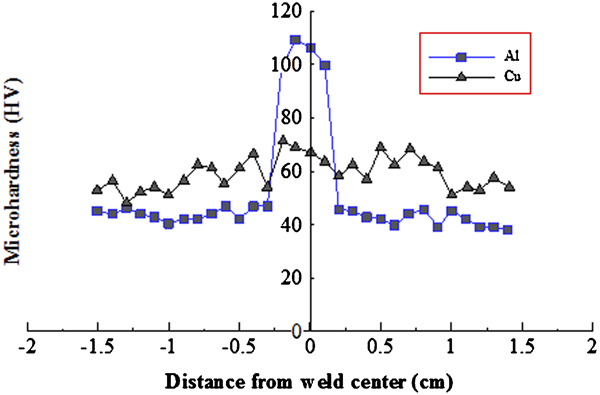
Hardness profile of Case I (welding conditions: 1400 rev min−1, 25 mm min−1)
Hardness profile of Case II (welding conditions: 1400 rev min−1, 25 mm min−1)
Conclusions
Friction stir welding experiments are conducted to lap weld the aluminium and copper sheets. Two test cases are considered, namely, Case I where the aluminium sheet is placed on the copper sheet and Case II where the positions of the sheets in the Case I are reversed. The effect of position of the materials with respect to the welding shoulder on the joint strength has been investigated through consideration of different thermomechanical factors such as cooling rate, peak temperature, hardness and LSFL. It is found that the effect of the materials position on the strength of the welded joint depends significantly on how it affects the heat input during the FSW process, which in turn affects the formation of defects. It is observed that in Case I where the aluminium sheet is in touch with the shoulder, due to the low thermal conductivity of Al, a relatively large amount of heat is generated in the weld area, which results in the formation of defect free fined grain zone in this area. On the other hand, in Case II less heat is generated due to the high thermal conductivity of Cu (the top plate). Therefore, the materials may not receive enough heat, which is needed for the sufficient plastic flow. This prevents the formation of channels and hence weakens the resultant weld. In general, the extreme heat generation in the weld zone halts the growth of the fracture load due mainly to the formation of brittle IMCs in the nugget.16 In the present work, however, merely a small difference between the cooling rates in Case I and Case II is observed. Therefore, the difference between the fracture loads in the two cases can be attributed to the difference between the heat inputs (peak temperatures) rather than the cooling rates. In other words, the peak temperature plays the main role in increasing the fracture load of the joint. The greater the peak temperature of the welding zone, the greater fracture load.