
Abstract
Tungsten inert gas (TIG) welding is most frequently used for arc study because it is clean and easy to control welding factor. Many researchers have been focused on the plasma stream to find out the relationship between vertex angle and penetration of the tungsten electrode in TIG welding. Moreover, researchers studied the characteristics of vertex angle and arc pressure and heat flux distribution of the tungsten electrode. In addition, they have carried out factors that have influence on the behaviour of the molten pool. Previous studies assumed that arc pressure was dominant for the force that physically works on the surface of the molten pool, neglecting the shield gas pressure. In addition, they have been focused on the protection of molten weld pool from exposure to the atmosphere. The object of this study is to investigate the effect of shield gas pressure on the surface of the molten pool by measuring the distribution of arc pressure and shield gas pressure compared with arc physical results of previous researches. In this study, we measured the distribution of arc pressure and shield gas pressure on the water cooled copper plate by changing the setting shield gas pressure and shield gas cup inside diameter. As the setting shield gas pressure increased and the shield gas cup diameter decreased, the arc radius got narrower due to the thermal pinch effect. Maximum arc pressure was slightly affected by setting the shield gas pressure and shield gas cup diameter. However, the shield gas pressure on arc surroundings was raised with the increasing setting shield gas pressure and the decreasing gas cup inside diameter. Orbital welding with convex back bead was successfully performed through molten pool control by shield gas pressure adjustment.
Keywords
Introduction
Tungsten inert gas (TIG) welding is an essential welding process in many industry areas such as ships, plant and nuclear power, since high quality weldment can be obtained from the TIG welding process and the demand is continuously increasing.1– 4 Many industries are currently transforming or planning to perform TIG welding from manual to automatic. However, it is hard to manage the welding quality in automatic TIG welding if it is not under a flat position. Especially, it is very complicated to manage the weld condition in pipe orbital welding because it requires all positions. For instance, it is difficult to have convex back bead under overhead and inclined-up positions.5 Thus, it is important to find the characteristics of arc phenomena and molten pool under the situation for successful orbital TIG welding. Modelling of manual TIG welding is applied to most automations.
To investigate the basic modelling, previous researches of arc phenomena have performed. Many researchers have reported on plasma stream for the relationship between vertex angle and weld penetration of the tungsten electrode in TIG welding,2 as well as the tungsten electrode form and the characteristics of arc pressure, current density and heat flux distribution.3,4,6– 9 Previous researchers ignored the shield gas pressure because the force on the molten pool surface was assumed to be the arc pressure. They focused on the protection of molten weld pool form exposure to the atmosphere.
The object of this study is to investigate the effect of shield gas pressure on the molten pool surface using former results of arc physics and measuring distribution of arc pressure and shield gas pressure.
For our purposes, the arc pressure distribution on the molten pool surface was measured and discussed, and then the validity of this study with the change of shield gas pressure and gas cup inside diameter was examined.
Experimental
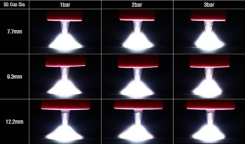
Figure 1 is a schematic diagram that indicates the welding condition to measure the arc pressure and shield gas pressure.10 Table 1 is a welding condition for arc and shield gas pressure measurement. Electrode, DCEN, 2% Th-W (diameter 3·2 mm) was used. Welding was performed under flat position, arc current of 200 A, arc length of 3 mm and Ar gas as shield gas. The welding conditions are as follows: the setting shield gas pressure is regulated with 1, 2, and 3 bar; the shield gas cup inside diameters are 7·7, 9·3 and 12·2 mm. Under this condition, current and arc voltage were measured, and then we took a photo of the arc shape.
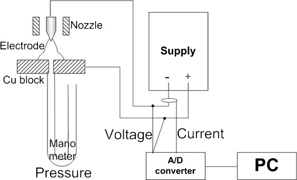
Schematic diagram of arc and shield gas pressure measurement using manometer
Figure 2 shows how to measure the arc radius. In the arc photo, the arc diameter11, 12 denotes the width that the arc contacts to the base metal, and the arc radius denotes half of the arc diameter.
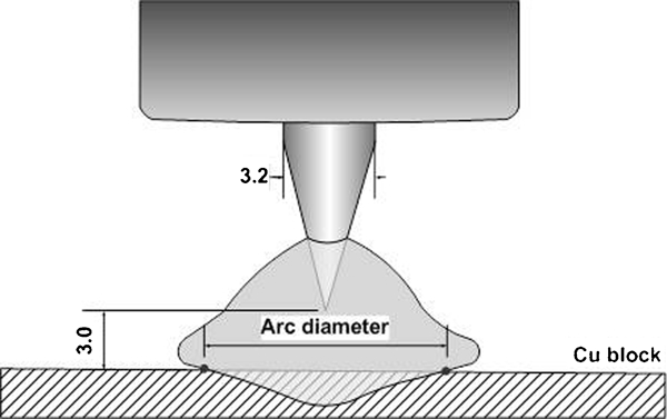
Schematic diagram of arc radius measurement
A manometer was installed beneath the anode Cu block drilled with 1·0 mm diameter. The arc pressures were measured on the anode base metal for 5 s.10 Penetrated from the top, the arc and shield gas pressures were measured, as shown in Fig. 3. The pressure of shield gas Ps was measured only following shield gas without arc, and the pressure of arc and shield gas PAS with arc and shield gas was measured simultaneously. Distilled water was put into the U type manometer, and the water was coloured by black ink. As the difference in the water head was generated by arc ignition, the arc pressures were calculated by means of the equation given for static pressure. For the purpose of arc pressure measurement from the centre of the arc axis to the radial circumference, the anode copper block was fixed on a work table and the torch attachment moving as Fig. 4.10 The location of the torch on the fixture was moved up to 6·0 mm radial distance. To reduce the measurement error, each measurement was repeated twice under the same conditions.
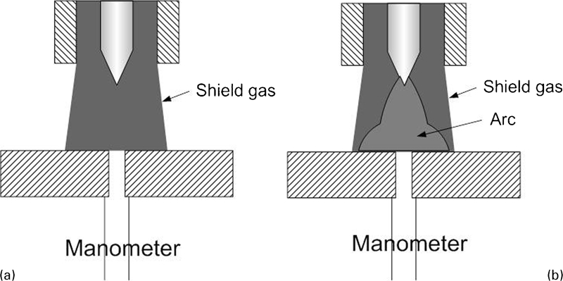
Schematic diagram of PS and PAS measurement using manometer

Schematic diagram of pressure measurement with radial distance from arc axis
Results and discussion
Arc shape according to setting shield gas pressure and shield gas cup diameter
Figure 5 shows arc shapes with each welding condition on 200 A and 3 mm in arc current and arc length respectively. Figure 6 was drawn from the arc radius in Fig. 5. As the setting shield gas pressure increased and the shield gas cup diameter decreased, the arc radius got narrower. While increasing the setting shield gas pressure or decreasing the gas cup inside diameters, the shield gas flow velocity around the arc increased. If the shield gas flow velocity was increased, the arc shape is cooler, and the arc was contracted due to the thermal pinch effect. Such an arc shape was affected by arc pressure3, 10 and heat flux;11, 12 thus, it could be changed by the weld bead profile.
Appearance of arc shape with welding condition in 200 A
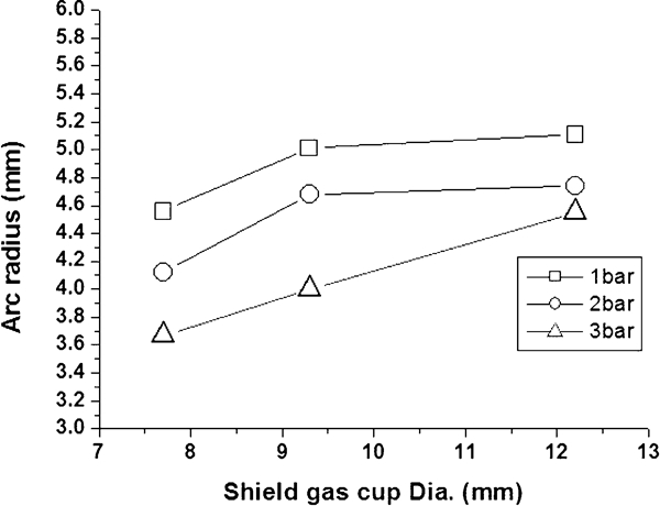
Arc radius with shield gas cup diameter and setting shield gas pressure
Welding condition for arc and shield gas pressure measurement
Distribution of arc and shield gas pressure with setting shield gas pressure and shield gas cup diameter
Figures 7 9 represent PS and PAS according to the setting shield gas pressure of the radius direction from the centre under electrode at the shield gas cup diameter of 7·7, 9·3 and 12·2 mm respectively.

Pressure distribution with variable setting shield gas pressure in shield gas cup Φ7·7
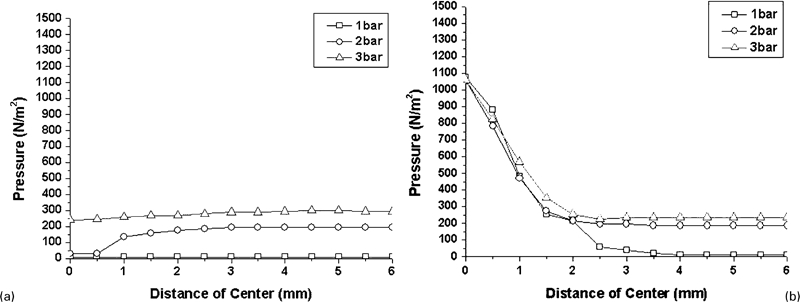
Pressure distribution with variable setting shield gas pressure in shield gas cup Φ9·3
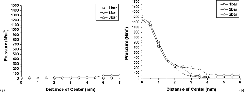
Pressure distribution with variable setting shield gas pressure in shield gas cup Φ12·2
Figure 7 shows the pressure distribution of PS and PAS with variable setting shield gas pressure in the shield gas cup (7·7 mm). According to Fig. 7, with increasing setting shield gas pressure, the maximum PS was also increased. While the pressure tends to be low under the electrode central part. The setting shield gas pressure hardly influenced the maximum PAS. Even if the setting shield gas pressure increases, there is hardly an increase in arc pressure, but the shield gas pressure on arc surroundings tends to increase. Therefore, the arc pressure distribution of PS and PAS affects the current density and heat flux, which may be changed by the weld bead profile.11, 12
Figure 8 represents PS and PAS at 9·3 mm in shield gas cup inside diameter. As in Fig. 7, PS showed that the shield gas pressure tends to be low under the electrode central part. At 1 bar in setting shield gas pressure, there was almost no pressure. There was also no influence of setting shield gas pressure at 1 bar of PAS on the graph as well.
Figure 9 shows the pressure distribution of PS and PAS with variable setting shield gas pressure in the shield gas cup (12·2 mm). The shield gas cup inside diameter is the biggest in this experiment; even if the setting shield gas pressures increase, PS and PAS did not change in this condition. The shield gas cup inside diameter affects the pressure distribution of PS and PAS throughout this experiment. When we try the TIG welding process, we have to consider the shield gas cup inside diameter as well as the shape of the tungsten electrode convex angle3, 11 and the arc pressure distribution with shield gas types.10, 13, 14
Effect of shield gas pressure that influences molten pool
Figures 7 9 show the pressure distribution of PS and PAS with variable setting shield gas pressure in the shield gas cup inside diameters as setting when the shield gas pressure increases; the pressure does not affect the arc pressure, while it predominates over arc surroundings. Thus, we tried the effect of the molten pool on the overhead position using the shield gas pressure distribution of PAS around the arc.
Figure 10 shows the effect of setting the shield gas pressure on bead height in overhead position of the TIG welding. It was welded by bead on plate welding at mild steel 3 t in overhead position. At this case, the welding conditions are follows: welding current 115 A, arc length 2 mm, welding speed 15 cm min−1 and shield gas cup inside diameter 9·3 mm, and then it is welded by changing the setting shield gas pressure into 1, 2, 3 and 4 bar respectively.
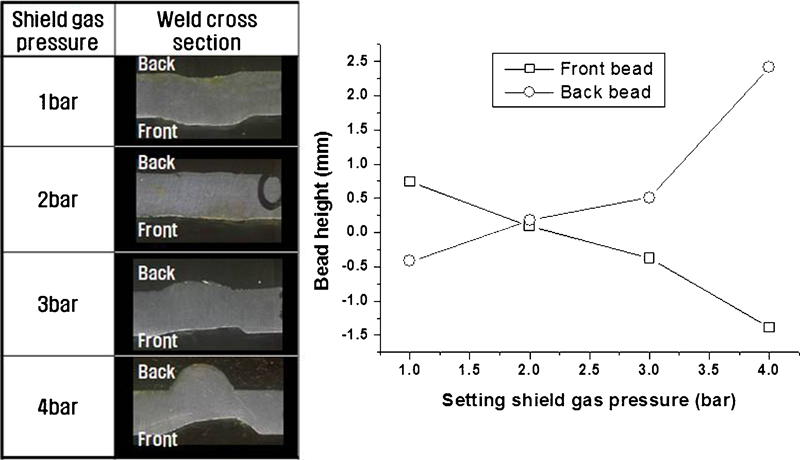
Effect of setting shield gas pressure on bead height in overhead position of TIG welding (mild steel 3 t, 115 A and arc length 2 mm)
With the increased setting shield gas pressure, it seems that the height of the front bead decreased but the height of back bead increased. From the results, it is considered that the behaviour of molten pool can be controlled using shield gas pressure.
Figures 11 and 12 show a model of the effect of low and high shield gas pressures on back bead height in the overhead position of the TIG welding molten pool.
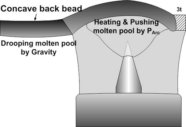
Effect of low shield gas pressure on back bead height in overhead position of TIG welding
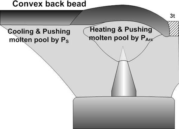
Effect of high shield gas pressure on back bead height in overhead position of TIG welding
Figure 11 indicates a model of the molten pool behaviour under the overhead position in case of general TIG welding or overhead position of low shield gas pressure. The arc can support the molten pool above the arc without dropping.3 As the arc passes through the molten pool, the arc force that comes into the molten pool disappears, and the molten pool falls down due to gravity and solidification. Finally, it formed a concave back bead.
Figure 12 shows a model of the molten pool behaviour under the overhead position in case of overhead position of high shield gas pressure. As shown in Fig. 11, the arc melts the base metal, and arc force pushes the molten pool upwards. As the arc goes by, the arc force in the molten pool disappears. However, the molten pool does not fall down by shield gas pressure of the arc surroundings, as shown in Fig. 7. Thus, it formed a convex back bead by being cooled due to the fast flow velocity of shield gas.
According to the previous researches, the forces that influenced the molten pool are known as arc force, gravity, surface tension, and so on.9, 15, 16 The results of this paper have to consider the shield gas pressure additionally.
Orbital welding by shield gas pressure
Figure 13 shows a weld cross-section with variable weld position. The welding conditions are follows; fixed U groove, butt joint, mild steel 6 t, root face 3 mm, welding current 150 A, arc length 2 mm, weld speed 10 cm min−1 and changed setting shield gas pressure by each welding position. Convex back bead is easily formed by the low shield gas pressure in all welding positions except for overhead and inclined-up positions. As with the overhead and inclined-up positions, the increasing shield gas pressure could form a convex back bead.
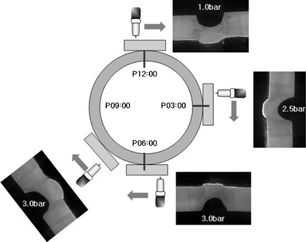
Weld cross-section with variable weld position (mild steel 6 t, 150 A and arc length 2 mm)
The authors tried another application, i.e. pipe orbital welding, using the results of setting shield gas pressure. Figure 14 indicates an application of pipe orbital TIG welding. Changing the welding current and setting shield gas pressure step by step successfully shaped a convex back bead. Even if the arc length was shortened to 2 mm, a convex back bead formed with stable arc was produced without touching electrode as the molten pool drops in the direction of gravity due to shield gas pressure in the overhead or inclined-up position. The reason for a successful convex back bead formation is the increased setting shield gas pressure because of an increased gas pressure distribution.
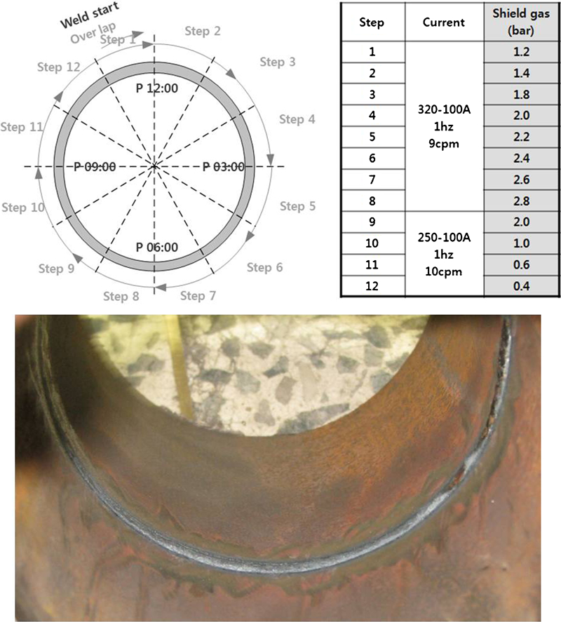
Application of pipe orbital TIG welding
Conclusions
Upon study on measuring the arc pressure and shield gas pressure that work on the surface of the molten pool, we found the followings.
Under the same welding condition, as the shield gas cup inside diameter decreased or the setting shield gas pressure increased, the arc radius was decreased. When setting the shield gas pressure increased or the shield gas cup diameter decreased, the flow velocity of shield gas around the arc increased. Therefore, it was believed that arc was cooled more and contracted by the thermal pinch effect as the flow velocity increased.
As the setting shield gas pressure increased, the maximum shield gas pressure also increased. This was the only trend of shield gas pressure, and the pressure tended to be low at the section just under the electrode. The tendency of arc pressure and shield gas pressure did not affect the arc pressure. However, as the setting shield gas pressure increased, the shield gas pressure around the arc increased.
With the increase in setting shield gas pressure, it seemed that the height of the back bead increased, while the height of the front bead decreased. It was considered that the behaviour of the molten pool can be controlled using shield gas pressure.
When applied to pipe orbital welding, changing the welding current and setting the shield gas pressure step by step successfully shaped a convex back bead. Even if the arc length was shortened to 2 mm, a convex back bead was formed, with the stable arc produced without touching the electrode as the molten pool drops in the direction of gravity due to shield gas pressure in the overhead position or inclined-up position.