
Abstract
The influence of threaded and wear simulated (half thread) tools on the mechanical properties of dissimilar Al alloy friction stir spot welds is investigated. With lower tool rotational speed settings, the failure loads of Al 5754/Al 6111 lap joints made using a threaded tool were clearly higher than that of a half thread tool. However, the failure load of the joints made using a half thread tool increased when the tool rotational speed increased, and finally, as the rotational speed was further increased, the failure load became almost the same as the failure load of joints made using a threaded tool. In Al 5052/Al 6061 butt joints made using the threaded and half thread tools, the area of the stir zone on the bonded cross-section corresponded with the actual bonded region on the fracture surface. Therefore, the thread on the rotating pin has limited influence on the mechanical properties of the friction stir spot lap joints.
Introduction
There is much interest in replacing resistance spot welding during the fabrication of automotive components with friction stir spot welding (FSSW), a variant of friction stir seam welding.1– 5 Although much research has been carried out on both friction stir seam and FSSW, the effects of tool wear on the final joint mechanical properties have received less attention. Tool wear during friction stir welding is primarily associated with the presence of a thread on the rotating tool. For example, self-optimization of tool shape resulted when the thread on the rotating pin is worn during friction stir seam welding of Al 6061–20 vol.-%Al2O3 and Al 359–20 vol.-%SiC Metal Matrix Composite (MMC) materials.6, 7 In both cases, the rate of tool wear is the fastest on the tip of the thread ridge among each part of the tool. In addition, tool wear did not produce any evidence of weld related degradation and worn tools without thread produced, good quality, homogeneous welds. It follows that machining a thread on the cylindrical rotating pin may not be required during friction stir seam welding in cases where excessive tool wear is likely to occur.
Additionally, it has been reported that in the case of friction stir welding, low flow strength materials do not necessarily need a thread on the rotating pin, and that even with high flow strength materials, if there is careful selection of the welding parameters, satisfactory welded joints can be produced even if there is no thread on the rotating pin.8 However, it has been confirmed that the stir zone width decreased and the ease of formation of the stir zone was limited during FSSW using a tool without a thread.9, 10 In addition, the presence of a thread on the rotating pin promoted intermixing and the downward and upward movement of material within the stir zone during FSSW.11 Recently, a number of tools have been proposed for FSSW.12– 15 However, since there are no results of welds made using a worn threaded tool in FSSW, although there are results of welds made using a worn threaded tool in friction stir welding, the influence of the thread on the rotating pin is possibly more important in the case of friction stir spot welds than in the case of friction stir welds.
This paper investigates the influence of thread wear on the microstructural features and mechanical properties of dissimilar Al alloy friction stir spot welds. The approach employed involves a comparison of the mechanical and metallurgical properties of joints produced using threaded, wear simulated (half thread) and no thread tools.
Experimental
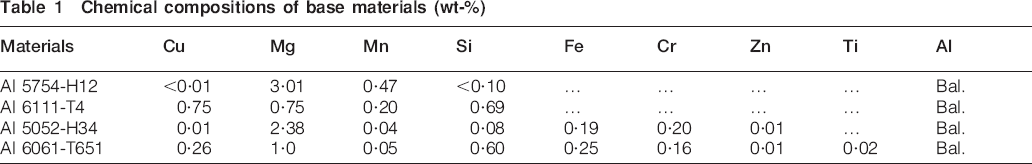
Different aluminium alloy sheet materials, namely 1·6 mm thick Al 5754-H12 (Al 5754), 1·5 or 3·0 mm thick Al 5052-H34 (Al 5052), 1·5 mm thick Al 6111-T4 (Al 6111) and 3·0 mm thick Al 6061-T651 (Al 6061), were employed during FSSW trials. The chemical compositions of all aluminium alloys are shown in Table 1. Sheets (100 mm long×25 mm wide) were spot welded using tool rotational speeds of 1000, 1500, 2250 and 3000 rev min−1, a plunge rate of 2·5 mm s−1 and a dwell time of 1 s. The depth of penetration of the tool shoulder into the surface of the upper sheet was 0·5 mm in the case of Al 5754/Al 6111 joints and 0·4 mm in the case of Al 5052/Al 6061 joints. The overlap length during overlap shear testing was 25 mm throughout.
Chemical compositions of base materials (wt-%)
The rotating tools were machined from heat treated H13 tool steel and had a hardness of 46–48 HRC. The tool shoulder diameter was 10 mm, while the length of the cylindrical rotating pin was 2·2 mm. Different pin designs were investigated, as shown in Fig. 1, namely a tool with a cylindrical rotating pin having an M4 thread, a wear simulated pin in which half of the M4 thread was removed during machining and a cylindrical unthreaded pin having a diameter of 4·0 mm. For the remainder of this paper, these three tool designs are referred to as the threaded, half thread and no thread tools.
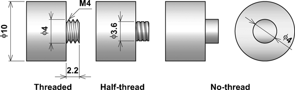
Different tool designs
Joint mechanical properties were evaluated using overlap shear testing using a crosshead rate of 1 mm min−1 with shims employed to maintain coplanar alignment. During optical microscopy, all test samples were polished and etched using Keller's reagent comprising 2 mL hydrofluoric acid, 3 mL hydrochloric acid, 5 mL nitric acid and 190 mL H2O.
The failure loads determined during overlap shear testing of friction stir spot welds produced using different tools and Al alloy combinations were related with Y and bonded width values and with the angles of curvature of the hook regions measured from transverse sections of the spot welded joints. The Y value is the distance from the tip of the hook region to the periphery of the keyhole in spot welded joints.16 Figure 2 is a schematic illustration showing the Y bonded width and curvature values. Hook regions are formed when the upper and lower sheets come into contact at the extremity of spot welds and comprise regions that exhibit oxide films and metallurgical bonding.16– 18 The bonded width is the width of the stir zone plus the width of the thermomechanically affected zone (TMAZ), which is formed beside the stir zone.16 The angle of curvature of the hook region was determined from transverse microsections by drawing a line parallel to the extremity of the hook region and measuring the angle with respect to a horizontal line through the sheet intersection.16 A magnification of ×500 was used when determining all bonded width and Y values. The tips of the hook regions were demarcated from transverse weld microsections. In spot welds that had smooth straight hook regions, the tip of the hook region was readily observable using optical microscopy with a magnification of ×500. The location closest to the keyhole periphery that exhibited metallurgical bonding was taken as the tip of the hook region in joints containing serrated hook regions. It has already been confirmed that the Y values measured using optical microscopy correspond closely with measurements of the distance from the tip of the hook region to the periphery of the keyhole in broken overlap shear test specimens.19
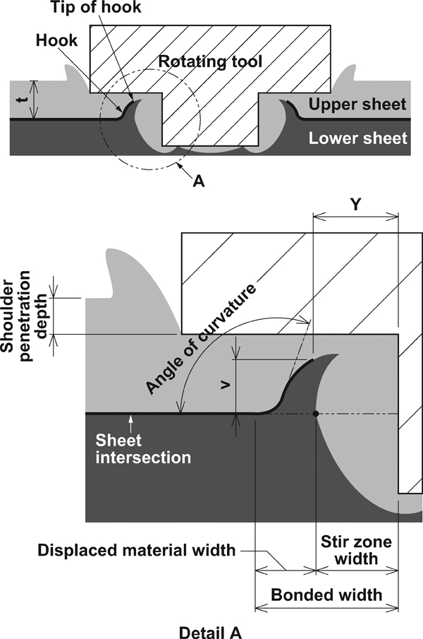
Schematic illustration showing measurement of stir zone and bonded widths, Y values, shoulder penetration depths and angle of curvature of hook regions
Results
Figure 3 shows the influence of tool design and tool rotational speed changes on the failure load of Al 5754/Al 6111 friction stir spot welds. When the threaded tool was used, the failure load was highest in joints made using a tool rotational speed of 1500 rev min−1. However, in joints made using the half thread tool, the failure loads increased linearly as the tool rotational speed increased from 1000 to 2250 rev min−1. Similar failure loads were found in joints made using threaded and half threaded tools with higher tool rotational speed settings (2250 and 3000 rev min−1). In contrast, the failure loads of joints made using the half threaded tool were lower (by ∼1·0 kN) in joints made using a rotational speed of 1000 rev min−1.
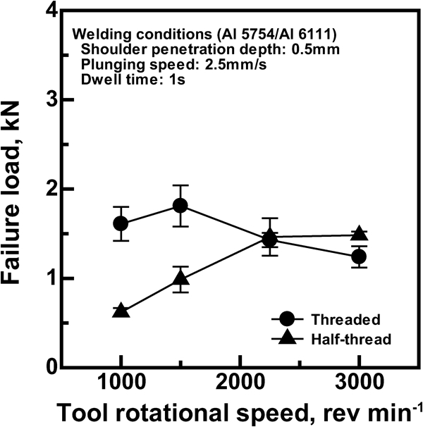
Relation between failure load properties and tool rotational speed in Al 5754/Al 6111 lap joints
Figure 4 shows the microstructural features of Al 5754/Al 6111 friction stir spot welds made using the threaded and half thread tools having the highest failure load. Arrow 1 in Fig. 4 shows the top of the hook region, while Arrow 2 shows the bonded width. An onion ring pattern was apparent in the stir zones of joints made using the threaded tool, as shown in Fig. 4a. The width of the TMAZ region formed beside the stir zone extremity was large, while the hook regions had serrated profiles in joints made using the threaded tool. Similarly, the stir zone and bonded widths were large in friction stir spot welds made using the half threaded tool and a tool rotational speed of 3000 rev min−1, as shown in Fig. 4b. An onion ring pattern was also apparent in joints made using the half thread tool when the tool rotational speed was 3000 rev min−1. However, the profiles of hook regions in friction stir spot welds made using the half threaded tool were smooth and straight at all tool rotational speed settings.
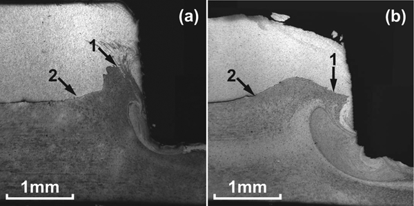
Profiles of Al 5754/Al 6111 lap joints having highest failure load properties: in friction stir spot welds made using a threaded and b half thread tools and a tool rotational speed of 1500 rev min−1
The stir zone width increased as the tool rotational speed increased in joints made using both threaded and half thread tools. This type of behaviour has been previously reported.11 However, the stir zone regions were always wider in spot welds made using the threaded tool.
Figure 5 shows the failure modes in Al 5754/Al 6111 friction stir spot welds made using threaded and half thread tools having the highest and lowest failure loads. In joints produced using the threaded tool having the highest failure load, as shown in Fig. 5a, the mode of failure involved crack propagation along the hook region followed by sample failure across the TMAZ region in the direction parallel to the sheet intersection. In contrast, sample failure occurred wholly along the length of the hook region in spot welds made using the threaded tool, which had the lowest failure load, as shown in Fig. 5b. Sample failure followed the length of the hook region with a small amount of failure across the TMAZ region in friction stir spot welds made using a half thread tool, which had the highest failure load, as shown in Fig. 5c. In the joint made using the half thread tool with the lowest failure load, as shown in Fig. 5d, sample failure occurred across the narrow TMAZ region created during the FSSW operation.
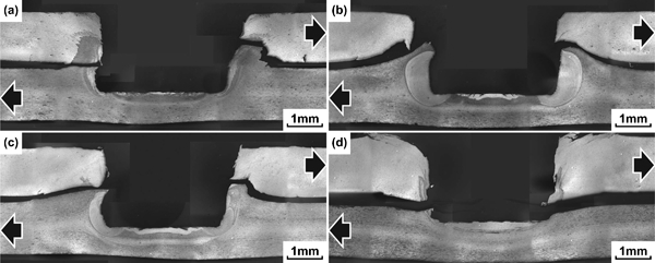
Failure modes in Al 5754/Al 6111 lap joints having a highest failure load properties when using threaded tool and rotational speed of 1500 rev min−1, b lowest failure load properties when using threaded tool and rotational speed of 3000 rev min−1, c highest failure load properties when using half thread tool and rotational speed of 3000 rev min−1 and d lowest failure load properties when using half thread tool and rotational speed of 1000 rev min−1
Figure 6 shows the influence of tool design and tool rotational speed changes on the bonded widths of Al 5754/Al 6111 friction stir spot welds. The bonded widths increased almost linearly in the joints made using the threaded and half thread tool with increasing tool rotational speed. The bonded widths in friction stir spot welds made using a threaded tool and tool rotational speeds of 1000 or 1500 rev min−1 were a little larger than in the joints made using the half thread tool. Since it has been recently suggested that the failure load of friction stir spot welds are higher when the bonded width increases,20 the improvement in failure load in joints made using half thread tools can be ascribed to larger bonded width values. However, the failure load of Al 5754/Al 6111 friction stir spot welds made using the threaded tool did not increase as Fig. 3 showed when high tool rotational speeds were employed. This is in spite of the fact that the bonded widths are larger in joints made using higher tool rotational speed setting.
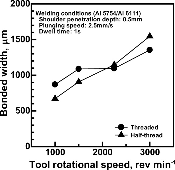
Relation between bonded width and tool rotational speed in Al 5754/Al 6111 lap joints
Figure 7 shows the influence of tool design and tool rotational speed changes on the Y values of Al 5754/Al 6111 friction stir spot welds. The Y values increased almost linearly in the joints made using the half thread tool with increasing tool rotational speed. In contrast, the distance from the tip of the hook extremity to the periphery of the keyhole (the Y value) decreased from 500 to 200 μm in joints made using the threaded tool. Therefore, the failure load of spot welds made using the threaded tool and higher tool rotational speed settings is lower, as Fig. 3 shows. It has already been confirmed that small Y values promote preferential test sample failures when the axial load increases during overlap shear testing of AM6021 and dissimilar AZ91/AZ31 friction stir spot welds.16 In dissimilar AZ91/AZ31 friction stir spot welds, for example, there was a linear relation between joint failure loads and measured Y values; in other words, the highest failure load values were found in joints with high Y values.16 Owing to the detrimental influence of small Y values on the joint mechanical properties, the behaviour overlap shear testing of Al 5754/Al 6111 joints produced using threaded and half thread tools is quite different.
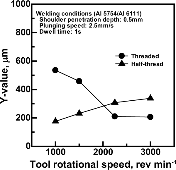
Relation between Y values and tool rotational speed in Al 5754/Al 6111 lap joints
Figure 8 shows the influence of tool design and tool rotational speed changes on the curvature values of Al 5754/Al 6111 friction stir spot welds. The curvature values also increased almost linearly in the joints made using the threaded and half thread tool with increasing tool rotational speed. The angles of curvature of the hook regions increased from 133 to 170° in joints made using the threaded tool as the tool rotational speed increased from 1000 to 3000 rev min−1. Similarly, the angles of curvature of the hook regions increased from ∼124 to ∼153° in joints made using the half thread tool when rotational speeds increased.
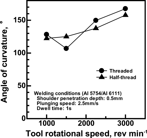
Relation between angle of curvature of hook region and tool rotational speed in Al 5754/Al 6111 lap joints
Discussion
Figure 9 shows schematic illustrations of the hook region profiles in Al 5754/Al 6111 friction stir spot welds produced using 1000 and 3000 rev min−1. The failure loads were highest in Al 5754/Al 6111 lap joints made using the threaded tool and a low tool rotational speed setting, because large bonded width and Y values were created in these joints, as shown in Fig. 9a. In contrast, the failure loads were lowest in Al 5754/Al 6111 friction stir spot welds made using the half thread tool and a low tool rotational speed setting, since the resulting welds had small bonded width and Y values, as shown in Fig. 9b.
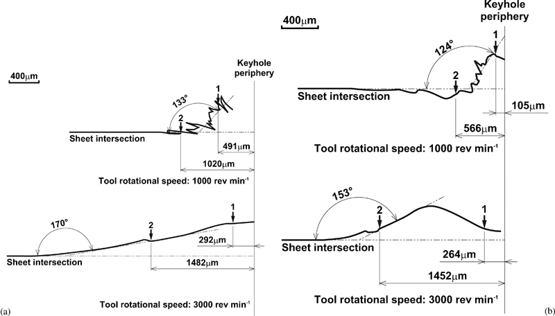
Schematic illustrations showing different hook regions in Al 5754/Al 6111 lap joints made using tool rotational speeds of 1000 and 3000 rev min−1
When the Y values are small though the bonded widths are large, the beneficial influence of a larger bonded width is removed. In Al 5754/Al 6111 friction stir spot welds made using the threaded tool with a lower tool rotational speed setting, though the failure loads were higher, the stir zone widths produced (promotion of larger stir zone widths being the main role of the thread) were still small. It follows that the bonded conditions were exceptional in the joints made using the threaded tool with a tool rotational speed of 1500 rev min−1. In Al 5754/Al 6111 friction stir spot welds, the stir zone widths of the joints made using the half thread tool always decreased compared with the joints made using the threaded tool. However, since both the stir zone and the bonded widths are increased when longer dwell times are applied, the failure loads of friction stir spot welds made using threaded and wear simulated (half thread) tools converge, and similar joint mechanical properties result. It follows that machining a thread onto the cylindrical pin only has a limited influence on the mechanical properties of dissimilar Al alloy friction stir spot welds and that welding parameters can be modified such that similar mechanical properties as those obtained with a threaded tool are achieved. In the preliminary experiment, stir zones were hardly ever produced in Al 5754/Al 6111 lap joints made using a no thread tool and with the same welding conditions as when a threaded tool was used. These results are similar to those of other studies, in which it has been reported that by changing the welding conditions the mechanical properties of friction stir spot welds made using a no thread tool can be obtained with similar results to the mechanical properties of welds made using a threaded tool.10
Figure 10 shows the microstructural features of Al 5052/Al 6061 lap joints produced using threaded, half thread and no thread tools and a tool rotational speed of 1000 rev min−1. It is readily apparent that the widths of the stir zone and TMAZ regions decrease markedly as the amount (area fraction) of thread on the rotating pin decreases. The stir zone widths that decreased markedly were 165 μm (threaded tool), 133 μm (half thread tool) and 86 μm (no thread tool), as in Fig. 10. However, the bonded widths in completed joints were remarkably similar, namely 1302 μm (threaded tool), 1303 μm (half thread tool) and 1294 μm (no thread tool). The Y values were 575 μm (threaded tool), 586 μm (half thread tool) and 465 μm (no thread tool), while the angles of curvature were 72° (threaded tool), 120° (half thread tool) and 90° (no thread tool).
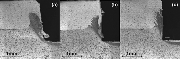
Profiles of Al 5052/Al 6061 joints made using tool rotational speed of 1000 rev min−1 and dwell time of 1 s
The failure loads of Al 5052/Al 6061 lap and butt welds produced using threaded, half thread and no thread tools are shown in Fig. 11. The failure load properties were similar in lap joints made using the different tools, namely 2·30 kN (threaded tool), 2·23 kN (half thread tool) and 2·14 kN (no thread tool). The failure loads in butt joints were also very similar, e.g. 1·98 kN (threaded tool), 1·95 kN (half thread tool) and 2·01 kN (no thread tool).
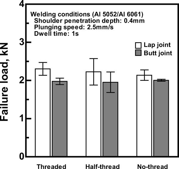
Failure load properties of Al 5052/Al 6061 lap and butt joints made using threaded, half thread and no thread tools: in all cases, tool rotational speed is 1000 rev min−1 and dwell time is 1 s
Figure 12 shows the microstructural features and fracture surfaces on the Al 5052 side of failed Al 5052/Al 6061 butt joints made using the threaded and half threaded tools. Arrow 1 shows the extremity of the bonded region, while Arrow 2 in Fig. 12a delineates the boundary of the unbonded region. Since the material located between Arrow 1 and Arrow 2 showed no evidence of fracture, as shown in Fig. 12b, this region played no part in the joint failure load process. Figure 13 shows schematic illustrations of the actual and apparent bonded regions in failed Al 5052/Al 6061 butt joints and the tensile strength properties of dissimilar butt joints produced using the threaded, half thread and no thread tools. The cross-sectional area of the actual bonded region was measured using image analysis software in a stereoscopic microscope using a magnification of ×10. The cross-sectional areas of the actual bonded regions were similar in butt joints made using threaded, half thread and no thread tools, namely 5·12, 5·77 and 5·42 mm2. Moreover, using the failure load values shown in Fig. 11, the calculated tensile strengths were 386, 339 and 370 MPa in Al 5052/Al 6061 butt welds made using threaded, half thread and no thread tools. Connected to this, the cross-sectional areas of the actual bonded regions were similar in Al 6061/Al 6061 butt joints made using the threaded, half thread and no thread tools, namely 6·93, 6·76 and 7·74 mm2. The failure load properties were also similar, namely, 1·67, 1·69 and 1·83 kN, in Al 6061/Al 6061 butt joints made using the threaded, half thread and no thread tools.
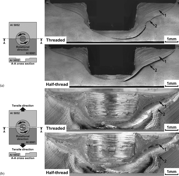
a profiles showing Al 5052 side of Al 5052/Al 6061 butt joint and b fracture surface showing Al 5052 side of Al 5052/Al 6061 butt joint
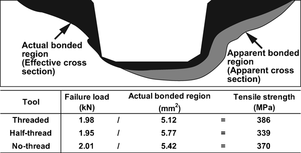
Schematic illustrations showing actual bonded region in failed Al 5052/Al 6061 butt joint and tensile strength properties of dissimilar butt joints made using threaded, half thread and no thread tools
The failure loads and actual bonded regions were almost the same in Al 5052/Al 6061 butt joints made using different tools. The main roles of the tool thread promote material flows in a vertical direction and produce a larger stir zone. Since the volumes of material flow were also similar when the area of the stir zone was almost the same in Al 5052/Al 6061 butt joints made using different tools, it follows that the thread on the rotating pin has negligible influence on the material flows in the horizontal direction in the friction stir spot welds made using the different tools. Moreover, from this result, it follows that the thread onto the cylindrical pin only has limited influence on the mechanical properties of dissimilar Al alloy friction stir spot welds. The results of the present study therefore correspond with the proposals made in recent papers, indicating that the failure load properties of friction stir spot welds are largely unaffected by thread wear during joining.8, 9, 22
Conclusions
The influence of simulated thread wear on the microstructural features and mechanical properties of dissimilar Al alloy friction stir spot welds was investigated. The following has been confirmed.
The highest failure loads during Al 5754/Al 6111 FSSW using a threaded tool were produced using a low tool rotational speed setting, producing joints that had lower failure loads. The failure loads of Al 5754/Al 6111 friction stir spot welds made using the wear simulated (half thread) tool increased linearly as the tool rotational speed increased.
Al 5754/Al 6111 friction stir spot welds made using a threaded tool had higher strength properties when lower tool rotational speed settings were applied. In contrast, the joints made using a half thread tool had lower strength properties when lower tool rotational speed settings were applied. However, the failure loads of the joints made using the threaded and half thread tools were similar when the tool rotational speeds were increased.
Machining a thread onto the cylindrical rotating pin had limited influence on the failure loads of lap and butt friction stir spot welds made between Al 5052 and Al 6061 sheets. Al 5052/Al 6061 lap and butt welds made using threaded, half thread and no thread tools had similar bonded widths, Y values and tensile strength properties.
From the results of Al 5052/Al 6061 lap and butt joints made using different tools, the main role of the thread of the cylindrical rotating pin was to promote material flows in the vertical direction, and there was negligible influence on the mechanical properties of joints and the material flows in a horizontal direction since the areas of the actual bonded region and the stir zone were almost the same.
Footnotes
Acknowledgements
The authors acknowledge the financial support from the Natural Sciences and Engineering Research Council of Canada. In addition, they wish to thank Kinki University, Hiroshima, Japan, for their financial support for Associate Professor A. Ikuta during his 1 year sabbatical at the University of Toronto. The authors also wish to thank the China Scholarship Council (CSC) for financial support provided to Y. Yin during the present investigation.