
Abstract
In situ TiBw and La2O3 reinforced titanium matrix composites were successfully fusion welded by the gas tungsten arc welding (GTAW) process and the weldability and feasibility for composites were studied, and uniform and defect free welds were produced with sound welding parameters. Microstructural observations showed that the joint has a distinctly identified weld zone characteristic. In addition, the distribution and size of TiBw in the weld became much more homogeneous and smaller. Moreover, the welded joints exhibited good mechanical properties at ambient temperature and the strength equal to the base metal at elevated temperature. The fracture mechanism of TiBw in the weld also was investigated.
Keywords
Introduction
In the past few years, titanium matrix composites (TMCs), especially reinforced by in situ formed Ti boride whiskers (TiBw), have been of great interest and exhibit a wide range applications in aerospace, military, nuclear and automotive1– 3 due to their high specific strength, specific stiffness and good fatigue resistance.4, 5 Besides, rare earth elements, effectively improving the thermal stability of titanium alloys, are also considered favorable.5– 7 To meet the industrial demands and make practical complex engineering components made of TMCs, appropriate joining methods producing high quality joints have been a necessity. However, the joining of TMCs together or with another material are faced with the difficulties caused by the great difference between titanium and reinforcement in physical and chemical properties.8
In the last decade, wide researches on the weldability and feasibility of different welding technologies for TMCs have been discussed, but solid state solutions are preferred,9– 11 because the fillers mostly used is the SiC fibre and particle and there has the reinforcement damage and excessive reactions between the fibre and matrix alloys. While the articles12, 13 verified that TMCs joints with satisfying properties could also be reached by the fusion welding technique, validly extending the application range of welded structure made of TMCs. As we know, the joining processes most applied for titanium alloys in industry are confined to fusion welding including gas tungsten arc welding (GTAW), plasma arc welding (PAW), laser beam welding (LBW) and electron beam welding (EBW).14 In order to produce ideal microstructures and joint strength, high power beam processes are widely studied because they can offer many benefits of high welding speed, low and local heat input, minimal loss of metal and high grade of final finish over regular techniques.15, 16 However, these beam processes mentioned above have the drawbacks of productivity viability and high capital equipment costs.
For the advantages of utility and economy, GTAW has been used widely for joining titanium alloys especially in sheet form.16 Gas tungsten arc welding has excellent characteristics such as superior weld, precise control of heat addiction, low distortion,14, 16 and provides the chance to attain joints of quality equal to EBW or LBW at lower costs. Besides, in situ TiBw is thermomechanically stable and essentially insoluble in Ti at all temperatures in the solid state as well as reaction free interfaces.17 These virtues can offer the favourable feasibility for welding TMCs. So far, few data are available on fusion welding TMCs. Therefore, it is necessary to understand the fundamental aspects and mechanism of joints of TMCs by the GTAW technique.
This paper describes an experimental research on the GTAW weldability of in situ reinforced TMCs.
Experimental procedure
The material used during trials was near α titanium alloy similar with IMI834 alloy, reinforced by in situ TiB 1·26 and La2O3 0·58 (vol.-%), 2 mm thick in annealed sheet form. The details of melting were seen in the former studies.2, 5 The autogenous fusion welding processes were performed on butted joint welded by a YR-HP6-A00 Motoman welding system and was accomplished with an infusible tungsten electrode of 2 mm diameter without filler metal. The schematic diagram of the experimental apparatus is shown in Fig. 1.
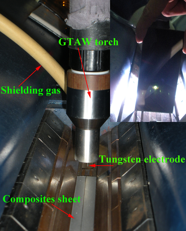
Schematic diagram of experimental equipment
During welding, joints were made perpendicular to the rolling direction of sheets. The main parameters of GTAW were welding current and welding speed. Both the top and bottom surfaces of welds were shielded using industrial purity argon gas to minimise the sheet surface oxidation. The parameters used are illustrated in Table 1.
Parameters for GTAW
Before welding, the plates (130×55×2·0 mm) were ground using a grinder and then cleaned with acetone. After welding, the joints were transverse sectioned at the vertical axis of welding direction for metallographic and mechanical evaluations by a linear cutting machine, and cross-sectional specimens were prepared via conventional metallographic methods. The etched samples were used to investigate the weld by an optical microscopy (OM, ZEISS Axio Imager A1) and scanning electron microscopy (SEM, JSM-6460). Room temperature tensile test (RTT) was evaluated by means of a MTS-810 test machine at a fixed strain rate of 10−3 s−1 for base metal (BM) and joints, and high temperature properties (HTP) of weldments were performed with the aid of SHIMADZU equipment at 600 and 650°C at a tensile rate of 0·4 mm s−1. Vickers hardness across the joint was measured at intervals of ∼0·2 mm using a 200 g load. The gauge dimension for tensile samples is 20×3·2×2 mm.
Results and discussion
Weld microstructure
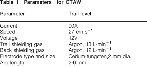
The as received macrograph and microstructure of welded joints for TMCs were shown in Fig. 2. It is clear that joints possessed the high quality geometry with uniform and clean weld, negligible distortion (Fig. 2a). This testified that the TMCs sheets of 2 mm thickness were fully penetrated by the GTAW technology under the given conditions and no difficulty related to the weldability by a single pass welding not employing the solder wire was found. Further metallographic observation indicated that several distinct microstructure zones appeared in the weld across the sample which were regarded as fusion zone (FZ), bond area (BA) and heat affected zone (HAZ) (Fig. 2b) and BM (Fig. 2c). Clearly, FZ has the more refined microstructure, while coarse grains were found in the BA region which is also called as the part of the HAZ close to the weld fusion line,14 and some whiskers substances with much smaller sizes in HAZ were found uniformly dispersed in the matrix.
a macrograph and b microstructure of GTAW joint and c BM
For GTAW, there are two major process parameters, namely the welding current (WC) and welding speed (WS) which influence the final weld geometry. The welding evaluations verified that two variables played a role on the joint characteristics in an inverse manner. Based on the natural behaviours of welding arc,18 the WS, directly affecting the value of weld heat input,15 decides the appearance of welds. With higher speeds, the required heat input and heating time for the weld are shortened and this will accordingly cause a narrower weld width and shallow penetration, even lack of penetration.14 On the other hand, increasing the WC is in favour of obtaining full penetration of joints, and the weld width also becomes wider. However, excessive WC can cause joints overheated to burn through.16 In a word, to reach a favourable form factor of weld (weld width/penetration) in GTAW TMCs, the changes of WC and WS will be in step with increase or reduction.
Formation and mechanism of TiB in weld
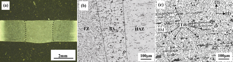
In order to intensively discuss the effects of GTAW process on the weld microstructure and existence form and distribution of reinforcements in the weld, the joint was studied by SEM. Figure 3 reveals the detailed microstructure of TMCs welds. The BM is composed of α phases with β phases at grain boundaries and the substances referred above in the matrix (Fig. 3d and Fig. 2c) are proved to be TiB whiskers in line with former researches2, 5, 19 with an aspect ratio of ∼4–5. It can be known that the FZ has elongated and refined β grains (Fig. 3a), while the coarse grains than FZ are found in BA (Fig. 3b), the microstructure of HZA, although similar with BM, has much smaller grain sizes and more uniform distribution of TiBw (white) (Fig. 3c). Visibly, another unique characteristic related to welding TMCs is that TiBw in the weld, e.g. FZ and BA (Fig. 3a and b) markedly changed their sizes and distributions compared with BM and redistributed at grain boundaries of β phases forming a network-like arrangement verified by Srinivasan et al.20 The aspect ratio of TiBw in FZ and BA with 14–16 is larger than that of BM. Besides, further examinations showed that β grains were composed of transformed α laths from β matrix forming a basket weave structure (Fig. 3e and f), and the α laths length/width ratio of FZ was 13·2 more than that of 11·4 of BA due to the changes of heat input. Moreover, in HAZ, TiBw has a higher aspect ratio of 8–10 than that of BM and seems to be from a single large size whisker split into pieces (Fig. 3g) which reveals the transmutation of TiBw during the GTAW process. In sum, the sizes and dispersions of TiBw in the weld can be notably better than the BM due to the effects of weld thermal cycle in welding TMCs.
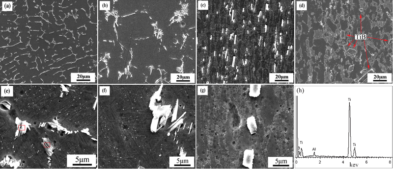
Images (SEM) of welds: a FZ, b BA, c HAZ, d BM and higher magnification images of e FZ, f BA, g HAZ, h EDS for rectangle area of e
As described above, in the process of welding TMCs, TiBw were kept in the weld confirmed on a selected area by EDS analysis (Fig. 3h), e.g. BA (Fig. 3e). For the EDS analysis, it should be noted that the extra diffraction peaks of Al attribute to the aluminium element in the matrix. Gas tungsten arc welding is a local process characterised by the instant high temperature melting and cooling course, where the temperature of welding heat source is higher than 4800°C (Ref. 21) with no less than 67% of energy transfer efficiencies for GTAW,22 much more than the fusion point of TiB (2200°C).23 Therefore, in the course of welding TiB will remelt into the liquid phase. However, the solid solubility of B in Ti is very limited, no more than 0·02 wt-%,3 and rapid solidification of molten pool can engender the titanium supersaturated solid solution with boron.17 Hence, solute enrichments resulted in constitutional supercooling and the nucleation rate of β phase in the weld was enhanced. Once nuclei are formed, the presence of boron rich layer will retard the grain growth allowing more grains to form in the surrounding area. In addition, the potential barriers formed by excess B in the solid/liquid interface make growth rate of titanium decreased. As a result, these two effects will generate the refined grains in FZ (Fig. 3a) and TiB will be the phase with higher undercooling to solidify in terms of the B-Ti binary phase diagram.24 Afterwards, the TiB precipitates and grows at the β grain boundaries shown in Fig. 3e and f. On the other hand, the lower interfacial energy of β grain boundaries where the β-Ti/β-Ti interfaces may supply a lively preferred nucleation for TiB. Moreover, at the high cooling rate of fused bath, the nucleation rate of TiBw can be enhanced, and hence the amount of TiB in the joint increased rapidly and the size became smaller during welding TMCs. Besides, TiBw can enhance the kinetics of phase transformation (β→β+α) by providing additional nucleation sites17 in the cooling process of molten pool. TiB precipitates are also likely to act as nucleation sites for α.20 The mechanism is likely to be by direct nucleation on TiB whiskers at the prior β grain boundary area. Consequently, the increase in nucleation ratio of α phase yields the refine size in α lath width (Fig. 3e and f). In contrast with FZ, the regions from BA to HAZ obtained less heat input by degrees, the former displayed coarse grains because of being superheated13 (Fig. 3b) and while the microstructure of the latter was similar with the BM with the smaller size and uniform distribution of TiBw (Fig. 3e).
Mechanical properties
Micorhardness
The microhardness profiles have been measured across the GTAW joint under the given welding condition of (TiB+La2O3)/Ti materials. The microhardness average value of the BM was 446 HV0·2 and the deviation value was 12·6 HV0·2. Figure 4 shows the results obtained for the welding condition and indentation location in the samples.
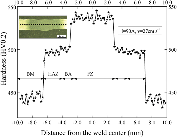
Microhardness profiles across GTAW joint under welding condition
The curve data show an evident increase in hardness in the weld, especially FZ up to 536 HV0·2 increased by 20% than the BM, which can be related to the much finer grain size and the hardening effect of fine broken whiskers embedded in matrix. Moreover, in the welding process, the strengthening effect also was observed in this region followed by the microstructural transformations from the intergranular β into α laths due to the rapid cooling from the welding temperature. In fact, the phenomenon of hardness increase in the weld is commonly found in the previous studies9 which included that the increase in hardness can be attributed to the microstructural transformations and the refinement of reinforcements in the weld.
Comparatively, the harnesses in BA and HAZ are slightly smaller than that of FZ. The average hardness in BA and HAZ is almost the same under the welding condition, 10·6% higher than BM. However, the hardness in BA seems to have the downward trend compared to HAZ because of the softening effect of coarse microstructures formed at a relatively slower cooling rate higher than the hardening effect of smaller whiskers in the matrix. It can also be seen from Fig. 4 that the scatter extent of hardness in the weld is lower than that of the BM which was attributed to more uniform distribution and smaller sizes of TiB of the weld (see Fig. 3). This reveals that the microstructure in the joint can be improved by the GTAW process.
Tensile test and fractographs
The tensile tests of GTAW joint were performed to discuss the effects of welding process parameters on the mechanical behaviours of welded assemblies as well as the BMs for comparison purposes. The tensile properties results of BMs and joints were shown in Fig. 5.
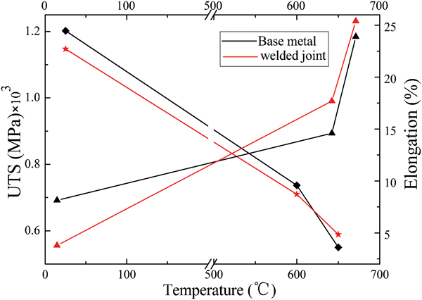
Tensile properties of GTAW joints at different temperatures
At room temperature, the ultimate tensile strength (UTS) of TMCs joint is 1150 MPa, practically equal to the BM strength of 1200 MPa and there is only a little decrease for the UTS of joints with a deviation no less than 5% after GTAW. In addition, the low value of elongation, less than 5% for joints can be attributed to the presence of TiBw which reduces clearly the property compared to the matrix alloy.4 Besides, the microstructure changes in the joint with phase transformations from β to α laths will lower the ductility14 because of the effects of thermal cycle of welding. Notably, the joint shows the excellent HTP, UTS up to 710 and 589 MPa at 600 and 650°C respectively and the full strength joint was obtained. With increasing temperature, the elongation was improved by degrees and the UTS of joints decreases in line with the early studies,5, 19 which is reasonably believed that matrix softening is more and more serious. Moreover, it is noteworthy that all the fractures of TMCs joints occurred at the BMs, showing that the true strength of welds is stronger than the BM, which is significant to the use of titanium material weldments. These behaviours are ascribed to the grain refinement of the matrix and smaller whiskers with network structure in the weld (Fig. 3), and can be verified by the micromechanism of the fractographs for the BM and joint (Fig. 6).
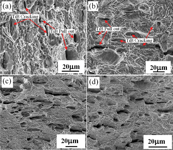
Scanning electron fractographs of BM and joint after tensile test at room and high temperatures
It is clear that the fracture mode of the BM and joint is similar with the mixture of ductile and brittle for the matrix and TiBw respectively at ambient temperature. The BM fracture has the sharper, deeper and numerous dimples, and the joint fracture surfaces shows smaller and rough dimples. Besides, cracked TiBw with an effective load transfer from the matrix during the tensile loading and deformation,4 are also examined by the red arrows. TiB engirded by the dimples are partly pulled out with increasing load which can tailor the joints tensile properties. In the course of loading, when the stress around the whisker reaches the critical value, the whisker cracking or interfacial debonding with the matrix happened and then are no more able to support the load. Furthermore, microscopic voids, affecting the ductility with voids density increasing25 were found formed in the tensile process of joints which were nucleated at locations of TiB. Li et al.26 proved that with filler volume fractions increasing, TiBw can block the growth and combining of voids effectively. In addition, Xiao et al.19 believed that whisker fracture occurs in priority to microvoid clustering. Thence, the joint formed much smaller and rough dimples than the BM, and the appearance of these damaged whiskers and void regions expanded and finally resulted in the facture and lower ductility.
While, at high temperature, with temperature increasing, the joints performed a visible plastic fracture, and more and distinct dimples were found in the fracture surface which indicates the favourable elongation (Fig. 6c and d). In the fracture surface of welded joints, due to the matrix softening and low interfacial strength, the number of debonding TiBw is examined to increase gradually. However, on the other hand, this indicates that the whiskers undertake the load as before during the high temperature tensile tests and is inclined to maintain the well bonded interfaces between TiBw and the matrix in the joint. Moreover, the network structure of TiBw has still remained the strengthening effect.4, 17 That is why with the increase in temperature, the joint strength is higher than the BM (Fig. 5), and the mechanism of TiBw deformation behaviours changed from cracking to debonding proved by Geng et al.5
From experimental results, it can be concluded that there is a relatively favourable and guided operating window for the fabrication of satisfactory joints with excellent tensile properties when GTA welding TMCs. In addition, it is learned that the joint specimens were not annealed after welding. However, the room and high temperature tensile test results prove that GTAW joints of TMCs exhibit a good continuity of the mechanical properties, even if these materials are coupled by a GTAW technology.
Conclusions
In summary, in situ (TiB+La2O3) reinforced TMCs were successfully welded with a GTAW process by a single pass welding without the filler metal and the defect free welds were obtained with the reasonable welding parameters. The joint microstructure consists of several distinct zones and the TiB whiskers in the weld relocating at grain boundaries become smaller and show more dispersed and uniform distribution due to the effects of weld thermal cycle. The welded joints exhibit excellent mechanical properties both at room and high temperature and the average hardness of the weld with a lower scatter extent is higher than that of the BM because of combined effects of smaller whiskers and refined grain sizes. Besides, all the fractures of the tensile specimens occur at the BM. The deformation mechanism of TiB whiskers changes from cracking to debonding with temperature increasing.
Footnotes
Acknowledgements
We would like to acknowledge a financial support provided by the Dawn Program of Shanghai Education Commission under grant no. 10SG15, 973 Program under grant no. 2012CB619600 and Shanghai Science and Technology Committee under grant no. 10JC1407500.