
Abstract
A new technique of in situ rolling friction stir welding (IRFSW) has been developed to reduce the residual stress and distortion. It can eliminate the weld flashes and improve corrosion resistance of the FSW seam. A new kind of FSW tool consisting of rolling balls was designed to achieve IRFSW. The residual stresses across the weld were measured by ultrasonic stress measurement experimental installation. The 3·5%NaCl solution was used to corrode the surface of welded joint, and corrosion current and potential were determined by an electrochemical analyser. The results shown that the residual tensile stress was reduced, the weld flashes were eliminated, and the corrosion resistance was improved. By applying IRFSW, the reduction of distortion was ∼34·4% compared with that of conventional FSW joint for aluminium plant with 3 mm in thickness and 300 mm in length.
Introduction
Friction stir welding (FSW) was a solid state welding process developed and patented by Thomas in The Welding Institute in 1991.1 The joining technique had many advantages such as high quality, low cost, low energy consumption and little environmental pollution. In particular, FSW is currently under extensive investigation for joining aluminium alloys in the aerospace industry.2– 4 Friction stir welding was considered to be the most significant development for metal joining in the past two decades.5 Although it was a solid state welding method, the FSW could still suffer from significant levels of residual stress, and associated distortion, which could be similar in magnitude to that found in fusion welds.6– 9 During fabrication, distortion can be a significant problem, and expensive post-weld repair procedures are sometimes necessary to overcome it.10 In order to reduce these defects, a liquid CO2 cooling technique was applied during FSW process.11 The cooling introduced a thermal tensioning effect on the cooling weld metal counteracting the forces which led to residual stresses and distortion.12 However, with regard to local cooling, the cooling substances might contaminate the weld metal.13 Thermal stress engineering techniques, global preheating and local thermal tensioning, were proposed.10 Global preheating of the components reduced the temperature gradient between the weld material and the surrounding parent metal. The amount of plastic strain generated during welding will decrease, resulting in the reduction of residual stresses.14 The local thermal tensioning introduced a local tensile strain which led to plastic elongation of the weld line material and the plastic elongation resulted in the reduction of residual stress.15, 16 However, it was not easy to weld the large plate with the thermal tensioning.13
In recent years, a new technique about application of rolling pressure had been invented.14 By using two rollers placed either side of the weld line following the FSW tool introduced significant compressive stresses in the roller contact area.14 One roller placed along the weld directly trailing the FSW tool could also help reduce the tensile weld line stresses significantly.14 Moreover, a surface enhancement technology which was called low plasticity burnishing (LPB) was used to reduce the tensile residual stress and distortion. Low plasticity burnishing tooling which was comprised of a ball that was supported in a spherical hydrostatic bearing was designed to process the weld surface after the FSW operation, producing a FSW seam with superior fatigue strength and surface finish.17 This technology had been demonstrated to produce a deep layer of highly compressive residual stress.18, 19
In the present work, a new technique of in situ rolling friction stir welding (IRFSW) was developed to reduce the residual stress and distortion, eliminate the weld flashes and improve the corrosion resistance of FSW seams. In situ rolling friction stir welding tool was comprised of a series of rolling tools which were fixed on shoulder. The aim of this paper was to examine the main effect on reducing the residual stress and distortion of this new process.
Experimental set-up
The material used is 2219 aluminium alloy with a thickness of 3 mm. The chemical compositions and mechanical properties of 2219 aluminium alloy are listed in Table 1. The IRFSW tool consists of a spacer and rolling tool made of alloy steel. The spacers are used to control effective rolling depth. Four rolling balls are fastened to spherical grooves by brazing, and the rolling tool connects with the shoulder through bolt fastening, which is shown in Fig. 1. The IRFSW processing are finished using an FSW machine (FSW-3LM-003). The geometries and features of the IRFSW tool are list in Table 2. To reduce the influence of welding parameters on the welding seam, the authors determine these welding parameters based on the preparatory experiments in which several welding parameters were tried including the design of the rolling balls, the speeds and the depth. The optimised parameters of FSW and IRFSW are summarised in Table 3.
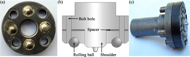
Photo of in situ rolling friction stir welding tool
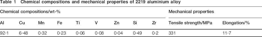
Chemical compositions and mechanical properties of 2219 aluminium alloy
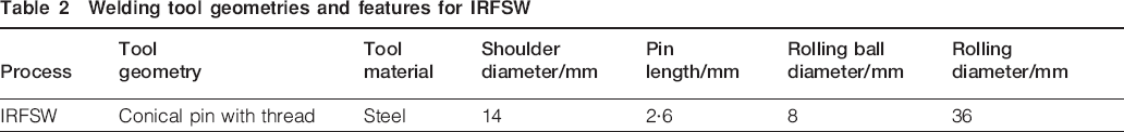
Welding tool geometries and features for IRFSW
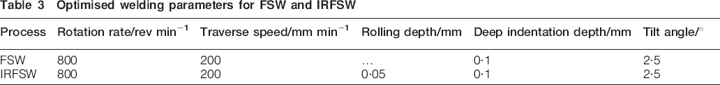
Optimised welding parameters for FSW and IRFSW
The IRFSW processing involves friction, stirring and rolling. The stir tool gets in touch with interface of aluminium alloy sheet, rubs against the inner interface, and self-cleans of the bonding surfaces. The rolling balls are pressed into the sheet for rolling the FSW seam. After the IRFSW process, the distortion of workpiece is measured. The authors record the surface points along either side of weld line every 1 mm, and then measure the distortion on the high precision granite surface plate BTMT-6399. The distribution of longitudinal residual stress is determined non-destructively by ultrasonic stress measurement experimental installation consisted of an ultrasonic impulse generator, a specific transducer, RIGOL oscilloscope with high speed digitising board and a laptop with a data processing programme. The ultrasonic impulse generator is made by SIUI. Two sensors make up the specific transducer whose frequency is 5 MHz, one emitter and the other receiver.20
To compare the erosion resistance of the sheets, the sheets are exposed to 3·5%NaCl solution at the room temperature. The scanning electron microscope Hitachi-S4700 is employed to capture a detailed view of the feature. The corrosion current and potential are determined by an electrochemical analyser CHI604C which is comprised of electrochemical cell. It is three electrodes system in which the sheet is used as a work electrode, the platinum piece is used as the auxiliary electrode and the saturated calomel electrode is used as the reference electrode. In the tests, cell current readings are taken during a slow sweep of the potential. The sweep is taken from −2 to +2 V and the scan rate is 0·01 V s−1.
Results and discussion
Photos of welding seams with different processes are shown in Fig. 2. During the conventional FSW process, the severe weld flashes are observed in most of the welds. The excessive weld flashes resulting from the outflow of the plastic material from underneath of the shoulder deteriorate the weld appearance. There are almost no weld flashes on the edge of the seam in IRFSW process. It is clear that the weld flashes on the advancing and retreating side have been eliminated by IRFSW process relatively. It can be attributed to the rolling balls. As the ball rolls over the sheets, the lateral extrusion pressure from rolling object prevents the outflow of the plastic material and helps smooth surface asperities.
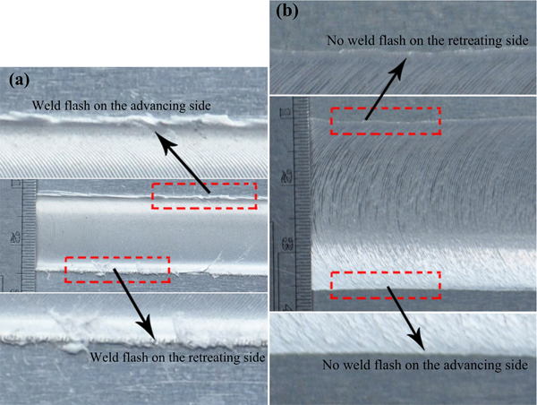
Photos of welding seams corresponding tool with different processes
Figure 3 presents the mean distortion comparisons along the weld line between conventional FSW and IRFSW. The experience result shows that the longitudinal distortion in IRFSW process decreases 26·3% in minimum, 48·7% in maximum, and has a 34·4% reduction on average compared with the conventional FSW. That is because high longitudinal tensile stresses exist across the weld zone, and these are in equilibrium with compressive stresses which arise towards the free edges of the sheet. These compressive residual stresses cause buckling distortion in welded sheets when they exceed a critical value of buckling stress.21 These results indicated that the introduction of rolling tool has an important effect on distortion reduction. In the IRFSW process, there is a 2·5° tilt angle between the stir pin and principal axis. The lateral extrusion pressure from the rolling balls is produced, which is shown in Fig. 4. This pressure can offset the residual tensile stress caused by the transient thermal expansion and contraction, and makes distortion decrease.
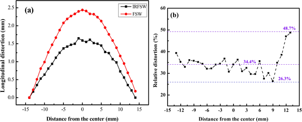
Longitudinal distortion comparisons along weld line between conventional FSW and IRFSW
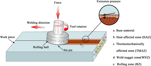
Lateral extrusion pressure produced by rolling balls and process of IRFSW
The variation of local longitudinal residual stress on the surface is shown in Fig. 5. In this experiment, the longitudinal residual stress distribution in the range of 50 mm distance from the welding centreline is measured by ultrasonic stress measurement experimental installation. The IRFSW can significantly reduce tensile residual stresses in the weld region and produce beneficial compressive stresses as shown in Fig. 5a. The residual stresses primarily result from the transient thermal expansion and contraction in the vicinity of the weld.13 The heat, resulting from the friction between shoulder and the base material, generates metal expansion, which is restrained by the surrounding cooler material. When the cooling process starts, the misfit in strain between the yielded and unyielded regions leads to residual tensile stress (predominantly parallel to the weld line). However, the technology of IRFSW produces extrusion pressure in the longitudinal direction. After welding, the sheet is released and not only tensile longitudinal stresses in the weld are compensated but even high compressive longitudinal stresses are generated in the weld zone, which have beneficial effects on corrosion resistance. The result also shows that the maximum tensile residual stress is located in the centreline of the weld. The longitudinal residual tensile stresses at the core of FSW are due to the tool action which strains and heats the material, as the cooling starts, the surrounding material does not allow to recover the strains and residual longitudinal stresses determined, positive ones at the core and negative ones close to the base material respectively.22 The relative reduction of residual stress compared with conventional FSW is shown in Fig. 5b. The relative reduction of residual stress of sheet around the rolling balls is much bigger. This attributes to the lateral extrusion pressure from the rolling balls. It can help reduce the tensile residual stress more obviously. The residual stresses are inevitable after the welding. These residual stresses can have a bearing on the service performance of the welded material with respect to fatigue and corrosion properties.23
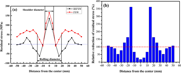
a variation of longitudinal residual stress on surface in conventional FSW and IRFSW process and b relative reduction of residual stress compared with conventional FSW
The corrosion feature of the welding seam surface with 400 s of exposure time is shown in Fig. 6. The erosion surface of conventional FSW seam is very rough and full of the caked corrosion layer. This is because chlorine ions absorb on the surface of electrode work, promote the dissolution of aluminium and result in the erosion of sheet. Compared with it, the surface of IRFSW seam is flat and uniform relatively. This attributes to the rolling pressure that makes the active point of weld surface decrease so that the corrosion resistance improves. The potentiodynamic polarisation curves under a series of welding speeds are shown in Fig. 7. The more electronegative the corrosion potential, the higher the tendency to erosion, and the higher the corrosion current, the more rapid the rate of erosion. The corrosion potential of IRFSW is found to be negative with respect to that of conventional FSW. The result also shows that the corrosion current of IRFSW is relatively low. The tensile residual stresses in FSW process can have a negative impact on service life, particularly on fatigue and stress corrosion performance. However, the tensile residual stress is reduced in IRFSW process, and the extrusion pressure produced from rolling tool can help improve the corrosion resistance.
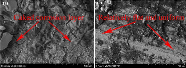
Photo of corrosion feature of welding seam surface.
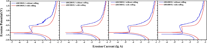
Potentiodynamic polarisation curves under series of welding speeds
A closer view to the IRFSW area reveals different zones which are shown in Fig. 8. Based on microstructural characterisation, four distinct zones, heat affected zone (HAZ), thermomechanically affected zone (TMAZ), weld nugget zone (WNZ), and rolling zone (RZ), have been identified. The RZ is located under the rolling tool and is the result of local plastic deformation. It is affected by the rolling balls. The WNZ is directly influenced by the tool pin. The nugget is the central weld region where the tool piece pin passes through the material. It is subjected to a high level of plastic deformation and frictional heating. The nugget size is typically slightly greater than the pin diameter. The grains are refined in WNZ. This refinement is the result of dynamic recrystallisation and combines action of high rate strain and elevated temperatures.24– 26 The TMAZ is the region which is beside the nugget. The transition appears sharp on the advancing side of the weld, particularly at the bottom of the weld, while it is more gradual and wide on the retreating side. Except the base material, the successive zone is HAZ. Meanwhile, the rolling tool introduces the rolling pressure that can have an important effect on the dynamic recrystallisation.
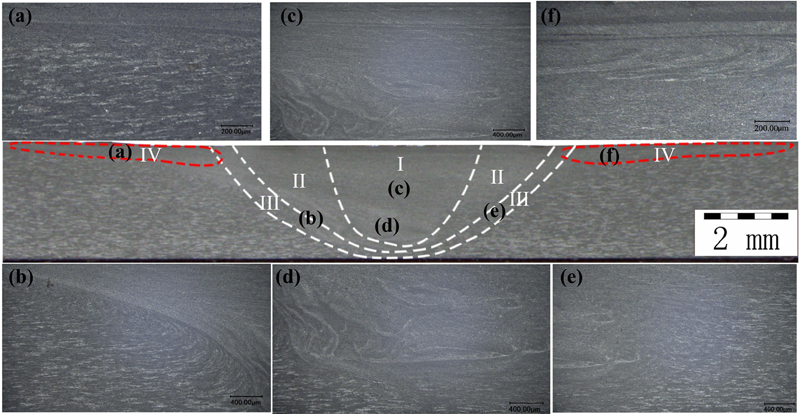
Optical macrograph of IRFSW joint for 3 mm aluminium plate: I: WNZ, II: TMAZ, III: HAZ, IV: RZ of IRFSW
For IRFSW, two parameters are very important: tool rotation rate and rolling depth. The rotation of rolling balls results in rolling and deformation of material around them. Furthermore, the rolling depth of rolling balls into the base material is important to produce better welds. The rolling depth is associated with the quantity of the overflowing plastic material. As FSW, the IRFSW advantages result from the fact that the process takes place in the solid phase below the melting point of the material to be joined. The benefits therefore include the ability to join materials which are difficult to join by conventional fusion welding, such as high strength aluminium alloy. However, it should be noted that one key problem about the new technology of IRFSW remains to study. The IRFSW process control models combined with the evolution of the structure and properties need to be built for achieving less residual stress and distortion welds.
Conclusions
A new technique of IRFSW using a tool consisting of rolling tool has been performed. Some experiments are performed on 2219 aluminium alloy with a thickness of 3 mm to investigate the efficacy of the new process. The results have been shown as the following.
In the IRFSW process, the pressure from rolling tool has a good effect on avoiding the excessive weld flashes and smoothes surface asperities compared with the conventional FSW process relatively.
Compared with the conventional FSW, the minimum and maximum reduction of the longitudinal distortion is 26·3 and 48·7%, and there is a 34·4% distortion reduction on average.
The maximum tensile residual stress is located in the centreline of the weld. The tensile residual stress translates the compressive residual stress out 10–25 mm away the centreline of the weld due to the rolling process.
The IRFSW process can reduce the residual stress and the joint has a higher corrosion resistance than that of conventional FSW.
These results suggest that the IRFSW has potential for practical application in industry as a means of reducing weld residual stresses and distortion.
Footnotes
Acknowledgements
The work was jointly supported by the National Natural Science Foundation of China (no. 50904020) and the Fundamental Research Funds for the Central Universities (no. HIT. NSRIF. 2012007).