
Abstract
In normal production of resistance spot welded galvanised structures, it is difficult to completely avoid surface breaking cracks. Known key factors to cause cracking are zinc coating, electrode wear during subsequent welding and insufficient electrode cooling. In this report, an embrittlement mechanism was investigated that could be coupled to the galvanisation method for dual phase steels. With identical bulk material and weld parameters, the first 50 spot welds were crack free with electrogalvanised coating, while only 10 out of 50 were crack free with hot dip galvanised coating. Energy dispersive X-ray spectroscopy analysis of the worn electrode surfaces used for welding of the hot dip galvanised coating revealed areas of aluminium oxide. Since aluminium oxide is a very strong isolator, the electrical resistance will increase, which in turn is suggested to increase the surface temperature of the spot weld and thereby increase the probability for liquid metal embrittlement and surface cracks.
Keywords
Introduction
Resistance spot welding is the main welding method for joining car bodies and truck cabins in the vehicle industry. With the introduction of advanced high strength steels (AHSSs), surface cracks of resistance spot welds were reported by Milititsky et al. 1 Yan et al. 2 showed that the occurrence of the surface cracks was foremost a result of improper process set-up and improper welding schedules. Sigler et al. 3 showed that crack depths can exceed half the sheet thickness in resistance spot welds of hot dip and galvanneal AHSS. The impact of deep surface cracks on the fatigue behaviour was investigated by Gaul et al. 4 No significant reduction in fatigue life was observed compared to crack free specimens. Despite this fact, it is desirable to avoid surface cracks in order to achieve high quality resistance spot welds.
To date, surface cracks have mainly been produced using forced welding schedules to provoke cracking. This has shown what maximum crack depths and crack locations that can be expected. Ma et al. 5 showed that surface cracks can be present both under and near the electrode surface contact area (Fig. 1). However, it is not yet fully investigated how frequent surface cracks are in running production with galvanised AHSS. In this report, normal welding schedules were used to investigate an embrittlement mechanism that could be coupled to the galvanisation method. A comparison was made between series of hot dip galvanised and electrogalvanised AHSS resistance spot welds. Surface cracking should not be associated with the phenomenon called hold time sensitivity,6 which otherwise is one of the known concerns for AHSS.
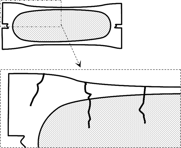
Illustration of resistance spot weld crack locations based on work carried out by Ma et al. 5
Based on the results from the welding trials, the influence of the zinc coating on the cracking mechanism is discussed. A hypothesis is that aluminium, in combination with zinc and copper, is the key factor contributing to surface cracks in the case of hot dip galvanised steels. Aluminium forms Al2O3 on the surface, which acts as an insulator. This will in turn increase the current density and thereby increase the temperature at the interface between the electrode tip and the steel sheet surface. Higher temperatures significantly increase the probability for surface cracks.
Experimental
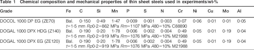
Two different coils of 1000 MPa dual phase steels with 1·5 mm sheet thickness were used in this study. These are designated according to their lowest tensile strength and are commercially available from 500 up to 1000 MPa.7 Table 1 shows the chemical composition and mechanical properties of the selected materials.
Chemical composition and mechanical properties of thin sheet steels used in experiments/wt-%
Coil number M21988 with hot dip galvanised coating was divided into two batches. The first batch remained unaffected, while the second batch was pickled, to completely remove the coating, and then electrogalvanised. In this way, two alternative galvanisation methods had been applied to sheet metal with identical chemical composition. Figure 2 shows cross-sections of the electrogalvanised coating and the hot dip galvanised coating. The thickness of the electrogalvanised zinc coating was measured to 9 μm, which corresponds to ZE120, i.e. 120 g of zinc per square metre per side.
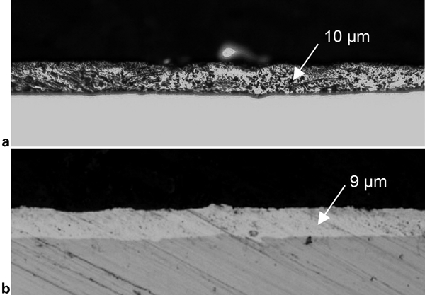
DOGAL 1000 DPX with a hot dip galvanised coating and b electrogalvanised zinc coating
Both these coatings contain mainly pure zinc with the exception of the hot dip galvanised coating, which also contains ∼0·5 wt-% aluminium.8 Glow discharge optical emission spectroscopy, with a LECO GDS 750A instrument, was used to analyse the element profile of the hot dip galvanised and electrogalvanised coating. Figure 3 shows the chemical composition as a depth profile starting from the surface and reaching 20 μm below the surface.
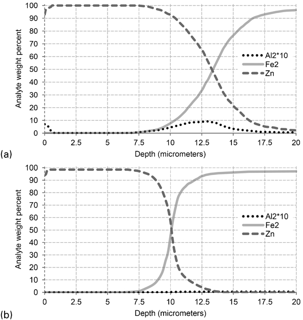
Glow discharge optical emission spectroscopy analysis from sheet surface down to 20 μm depth of DOGAL 1000 DPX with a hot dip galvanised coating and b electrogalvanised coating
Compared to the electrogalvanised coating, there is also aluminium in the hot dip galvanised coating. The aluminium profile shows that the aluminium content is not distributed evenly throughout the zinc layer. The greater part of the aluminium content is located to the first 0·5 μm at the surface and at the interface between the coating and the sheet metal. As aluminium is a highly reactive metal, it will be oxidised by the air forming aluminium oxide on the surfaces. Aluminium oxide is a very strong isolator, which will affect the electrical resistance during welding. Higher resistance increases the heating of the surface, which in turn might increase the probability for surface breaking cracks.
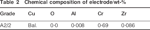
Another possible source of aluminium, apart from the sheet metal coating, is the electrodes. Therefore, glow discharge optical emission spectroscopy analysis was performed on the bulk metal of the standard A2/A grade electrodes used in this study. Table 2 shows, however, that the aluminium content in the electrodes was very small.
Chemical composition of electrode/wt-%
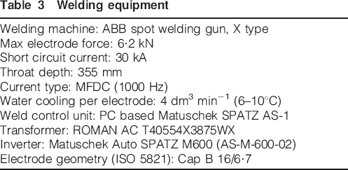
All welding trials were carried out on samples in as received condition without wiping off the mill oil. An ABB spot welding gun, together with a Matuschek AutoSPATZ M600 inverter, was used for the spot welding trials. A series of 160 spot welds was welded on plane coupons with a size of 125×38 mm for each weld schedule. Five spot welds were welded on each coupon with approximately 1·5–2 s between each weld. The details of the welding equipment used in this study are provided in Table 3.
Welding equipment
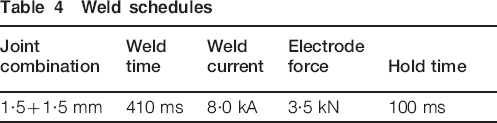
The weld schedules used in this study represent normal production parameters (Table 4). For comparison, one spot weld series was welded with extended weld time (615 ms) and lower weld current (6·25 kA). The minimum required weld plug size of 6 mm was achieved for all spot weld schedules with the weld current level set 0·7 kA below the spatter limit. The hold time, which is the duration at which the full electrode force is maintained after the weld current end, was set to 100 ms to ensure normal cooling of the spot weld surfaces.
Weld schedules
External measurement devices were used to monitor the welding process. Electrical measurements were performed using a Yokogawa DL708 oscilloscope. Test probe clamps were put directly on the electrodes to minimise any errors in the measurement. The current was measured using a Rogowski current transducer, and the electrode force was measured using a SPATZMulti04 weld recorder.
Gaul et al. 9 investigated different methods to detect spot weld discontinuities and found that surface cracks could be detected with a light optical microscope. Figure 4 illustrates how the crack length could be measured using a number of measuring lines. The crack lengths were measured on both sides of the spot weld and summarised to give the total crack length.
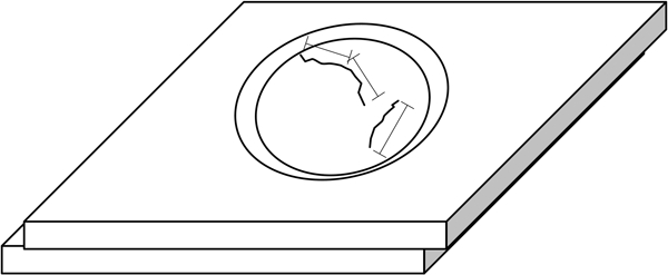
Crack length measurement under microscope
Results
Cracking was observed in spot welds made with regular weld schedules used for high volume manufacturing using spot welding guns, i.e. the weld parameters were not adjusted to provoke cracking, which often is the case in other articles. Figure 5 shows a spot weld with a crack length of 5 mm measured at the surface, and the maximum crack depth corresponding to half the sheet thickness. The larger crack is extended from the surface through the heat affected zone and down into the weld metal. From the cross-section, it is also shown that the electrode indentation was small and that the electrodes were aligned during welding. Thus, the cracks are hereby not caused by large electrode indentations or misaligned electrodes.
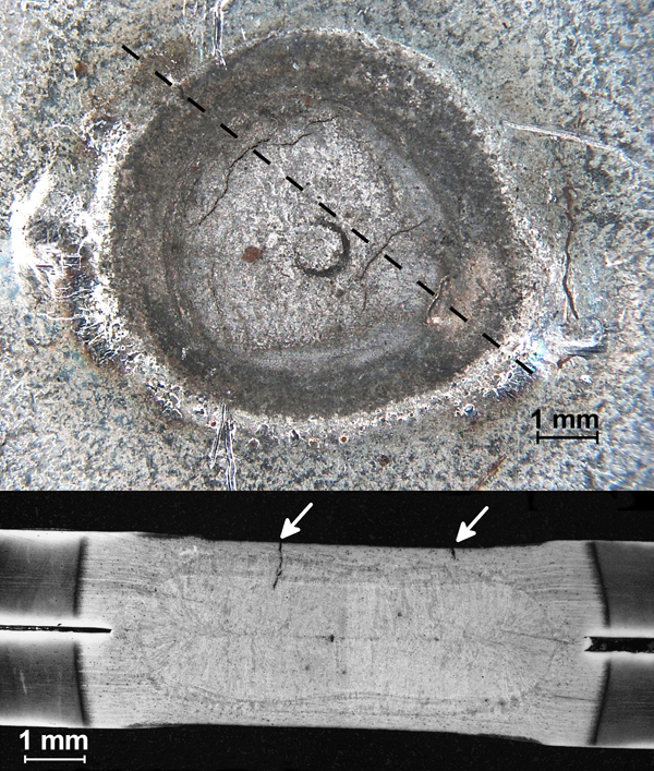
Surface breaking crack in spot weld of DOGAL 1000 DPX with hot dip galvanised coating. Top surface (above) and cross-section (below)
It is difficult to outline a single type of surface breaking crack since the cracking pattern is unique for each spot weld. However, the cracking pattern can be illustrated depending on the location and extension of the surface breaking cracks. Figure 6 shows different appearances depending on the occurrence and length of the cracks. In the case of small radial or circular cracks smaller than 1 mm, they were found 0·5–1 mm from the perimeter of the spot weld. Other cracking patterns could be visualised as a network of small cracks in the centre or along the perimeter of the spot weld with a length of 0·2–2 mm. Larger, continuous cracks longer than 2 mm and wider than 20 μm commonly displayed separate or branch-like cracks.
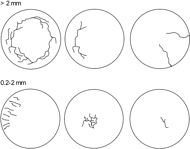
Location and extension of surface breaking cracks found in this study
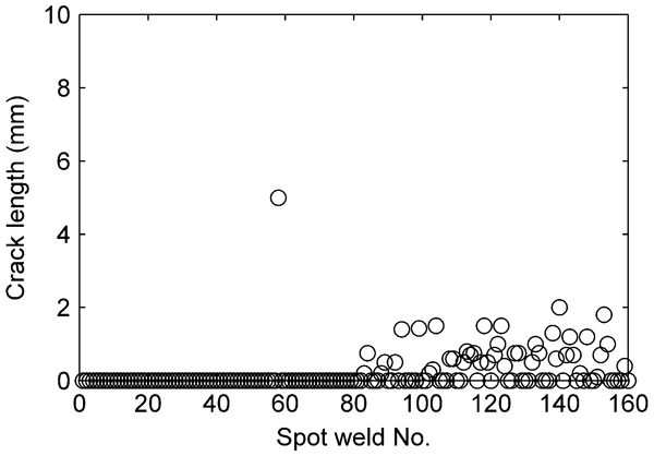
Figure 7 shows the crack length as a function of the spot weld number for hot dip galvanised DOGAL 1000 DPX (Z140). Even though the crack length increases with the number of welds made, the occurrence of cracks shows large variation. There are frequent spot welds without any crack indications where the previous and the next spot welds display large crack lengths. When taking into account all surface cracks, from smaller cracks ∼0·2 mm in length to larger continuous cracks, >50% of the spot welds have surface cracks. In the case of cracking on both sides of the spot welds, these two crack lengths were summarised. The tendency was that cracks occurred more frequently towards the positive electrode cap than towards the negative electrode cap.
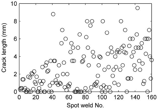
Surface breaking crack length as function of spot weld number for DOGAL 1000 DPX (Z140), t = 1·5+1·5 mm
It is known that high welding currents conduce surface cracking in spot welds.2 Thus, reducing the welding current and extending the welding time would be a quick solution to avoid cracking. However, in high volume production, the cycle time is a critical parameter and extending the cycle time is not an option in most cases.
The phenomenon is still interesting, and in order to evaluate the influence of the welding time on the occurrence of surface breaking cracks, a test with longer welding time was performed. The weld current was balanced to give equal heat input for the spots welded with normal and long welding times. Compared to the spot welds welded with 410 ms welding time and 8·0 kA weld current (Fig. 7), the occurrence of spot welds with surface breaking cracks was much lower for the spots welded with 615 ms weld time and 6·25 kA weld current (Fig. 8). The average crack length was also shorter.
Surface breaking crack length as function of spot weld number for DOGAL 1000 DPX (Z140), t = 1·5+1·5 mm welded with 615 ms
Besides the zinc coating type, the chemical composition of the bulk materials is different between the DOGAL and DOCOL sheet materials. Hot dip galvanising subjects the sheet material to a heat treatment in contrast to electrogalvanising, which is a cold coating process. Therefore, the DOGAL sheet material has a higher content of alloying elements due to the additional heat treatment from the hot dip galvanisation process (see Table 2). Figure 9 shows the crack length for spot welds for electrogalvanised DOCOL 1000 DP (ZE70) steel with 5 μm zinc coating thickness. Only one surface breaking crack was observed on the spot welded electrogalvanised sheet material as compared to the hot dip galvanised DOGAL 1000 DPX (Z140) showing cracks in >50% of the spot welds.
Surface breaking crack length as function of spot weld number for DOCOL 1000 DP (ZE70), t = 1·5+1·5 mm
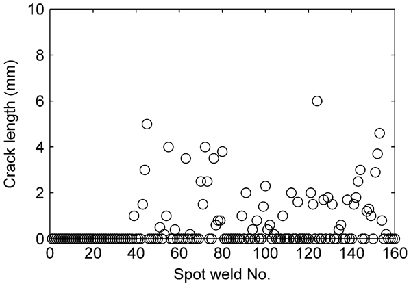
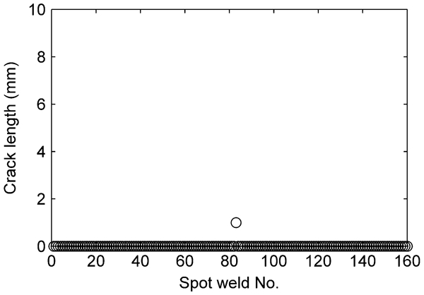
To eliminate the influence of the chemical compositions on the occurrence of surface breaking cracks for the hot dip and electrogalvanised sheet material, a comparison was made by re-electrogalvanising the DOGAL 1000 DPX steel. Thus, the sheet materials were identical for both zinc coating types. Compared to the spots welded on the hot dip galvanised DOGAL 1000 DPX (Z140), the spot welds made on the electrogalvanised DOGAL 1000 DPX (ZE120) showed a significantly lower amount of surface breaking cracks (Fig. 10). More than 50 spots were made before a surface crack was noted. It is evident that the zinc coating type has a strong influence on the occurrence of surface breaking cracks.
Surface breaking crack length as function of spot weld number for DOGAL 1000 DPX (ZE120), t = 1·5+1·5 mm
The spot weld experiments have shown that the occurrence of surface breaking crack increases as the electrode caps start to wear during continuous spot welding. The zinc coating type has a strong influence on surface cracking of spot welds. Compared to spot welds with electrogalvanised coating, the frequency of spot welds with cracks was >50% higher for the hot dip galvanised spot welds. There is also a correlation between the welding current and the occurrence of surface breaking cracks.
Discussion
To verify the hypothesis that aluminium in combination with zinc and copper is the key factor contributing to cracking, the surfaces of used electrodes were analysed with energy dispersive X-ray spectroscopy. Quantitative grid measurements of the surfaces were achieved using a Zeiss SIGMA VP field emission scanning electron microscope equipped with an Oxford Instruments X-Max Large Area energy dispersive X-ray spectroscope. Figure 11a shows the aluminium pickup on the electrode tip surface after welding 100 spots on hot dip galvanised sheets. The aluminium content is located to the area of the electrode, which is in contact with the sheet material during welding. Small islands with up to 8 wt-% aluminium were found along the perimeter of the electrode tip. This indicates that aluminium is picked up continuously from the coating of the sheets during the subsequent spot welding. Almost no aluminium was found on the electrode tip surface after welding 100 spots on electrogalvanised sheets (Fig. 11b). The latter was expected since the amount of aluminium in the electrogalvanised zinc coating is very low. Also, the electrode copper alloy consists merely of 0·008 wt-% aluminium. The results from the welding trials showed a significant difference in occurrence of cracks between the two zinc coatings. With identical bulk material and weld parameters, the first 50 spot welds were crack free with electrogalvanised coating, while only 10 out of the 50 first welds were crack free with hot dip galvanised coating.
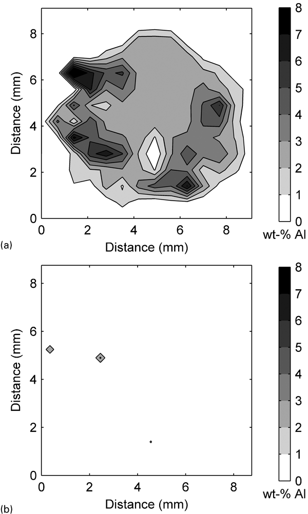
Aluminium content on electrode surface after welding 100 spot welds with a hot dip galvanised DOGAL 1000 DPX (Z140) and b electrogalvanised DOCOL 1000 DP (ZE70)
Owing to aluminium's high affinity to oxygen, the aluminium content on the surfaces will form aluminium oxide (Al2O3), which has completely different electrical properties than aluminium metal. While aluminium is a highly conductive metal, Al2O3 is a strong insulator with high dielectric strength. Tumuluru10 has shown that a very fine layer of Al2O3 with a thickness of 10 nm has a dielectric strength of 1 V at room temperature. This value should be compared to the voltage over the electrodes, which is ∼1·6 V during welding. Thus, a 16 nm thick layer would act as an insulator in this case. However, the electrode surfaces are not completely covered by a homogenous layer of Al2O3. It is more likely that an Al2O3 layer will build up in thickness and size during the subsequent welding. Kondo et al. 11 made a surface analysis of an electrode tip showing areas with up to 20 wt-% oxygen. With increasing size and thickness of the isolating layer, the effective conductive area of the electrodes will be reduced. This in turn will increase the current density and thereby increase the temperature at the interface between the electrode tip and the steel sheet surface.
The formation and propagation of surface breaking cracks involve interactions of metallurgical, thermal and mechanical factors.12 A weldability study by Milititsky et al. 1 indicates that zinc coated steels may develop liquid metal embrittlement (LME). The zinc coating on the sheet surface, excessive weld heat, excessive weld tip wear, alloying of the electrodes, electrode misalignment and poor electrode cooling were considered important factors in causing LME and surface cracking.
Since the welding trials in the present study were performed with normal welding parameters, the significance of these parameters could be disregarded except for the zinc coating and alloying of the electrodes. The welding trials made in this study showed that the occurrence of surface breaking cracks could be significantly reduced by lowering the weld current from 8·0 to 6·25 kA and thereby reducing the spot weld surface temperature. With the assumption that the spot weld surface temperature increases due to Al2O3 layers at the electrode surfaces, it is likely that the probability for surface breaking cracking also increases.
Figure 12 shows a measurement of the electrical resistance and weld current during the weld cycle with hot dip galvanised and electrogalvanised DOGAL 1000 DPX. The rapid drop in dynamic resistance during the first 0·02 s is a result of the decreasing film resistance at the faying surface and electrode/workpiece interface. From that point, the bulk resistance and contact resistance rapidly increase, reaching a peak value where the resistance at the faying surface has started to decrease. The next stage is characterised by a decrease in resistance until the end of the weld time. As the bulk metal is softening, the applied electrode force is starting to make a deeper and deeper indentation into the bulk material. This results in decreased contact resistance due to larger contact area and reduced thickness of the bulk material, which counteracts the increase in bulk resistance.13 Compared to the hot dip galvanised spot welds, the electrical resistance is ∼1/10 lower for the electrogalvanised spot welds during the stage where the contact resistance increases.
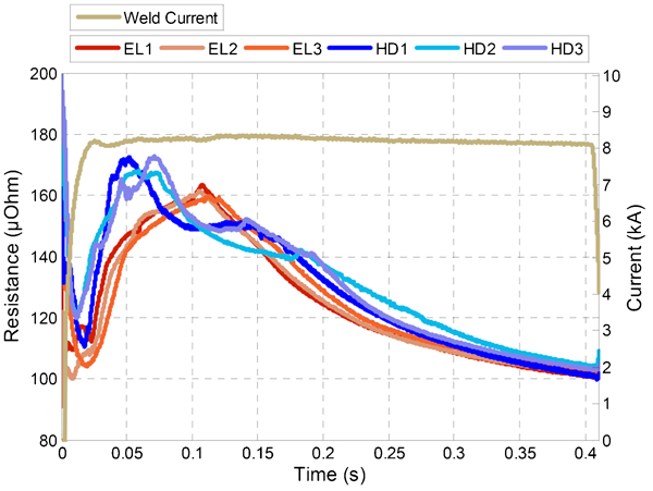
Electrical resistance during spot welding of DOGAL 1000 DPX with electrogalvanised (EL1–EL3) and hot dip galvanised zinc coating (HD1–HD3)
The heat generated by the weld current flowing through the bulk metal can be expressed by Joule's first law: Q = I 2 Rt, where Q is the heat generated by a current I of electrical resistance R for a time t. With the assumption of uniform flow of electric current, the heat generated in the bulk metal can be rewritten as: Q = I2rhoL/At, where rho is the bulk resistivity with thickness L and contact area A. The heat generated shows a linear dependence with the contact area. Thus, an increase in contact area due to softening of the bulk material reduces the heat generated at the electrode/workpiece interface. The opposite is true for surface layers of Al2O3, which reduces the contact area and increases the surface temperature of the spot weld.
For example, if the contact surfaces of electrode tips are covered to one fifth by an isolating layer of Al2O3, the heat generated at the electrode/workpiece interface will increase with the same proportion for a given weld current. Taking into account the temperature dependency of the electrical resistivity, there will be an extra addition to the heat generation from the isolating Al2O3 layers. The comparison made in this study between two different weld schedules with matching heat input shows that the occurrence of surface cracks could be reduced by >50% by decreasing the weld current. With extended welding time, the electrode cooling will work much more efficiently and thereby reduce the surface temperature.
A study by Sigler et al. 3 showed that weld cracks were more explicit in regions where the steel had fully transformed to austenite during the welding process. Béal14 showed that LME in AHSS occurs only at temperatures for which austenite has started to form. With increased heat developed at the interfaces, due to layers of Al2O3, it is possible that the temperature reaches the austenite region and causes surface cracking.
Conclusions
This report has shown that surface cracking of resistance spot welded dual phase AHSS is coupled to the galvanisation method. Resistance spot welds were more prone to surface cracking with hot dip galvanised coating as compared to electrogalvanised coating. Using regular weld schedules and hot dip galvanised coating, cracks were observed already during the initial welds, to further increase in number and crack length during the spot weld series. With electrogalvanised coating, the first 50 spot welds were crack free.
During spot welding of the hot dip galvanised material, aluminium was found on the electrode surface and build-up of aluminium oxide (Al2O3) was assumed. The Al2O3 layers increase the electrical resistance, which in turn is suggested to increase the surface temperature of the spot weld and thereby increase the probability for LME and surface cracks.