
Abstract
Experimental measurements of torque, traverse force and thermal cycles in friction stir welding (FSW) are challenging due to the simultaneous rotational and linear motions of the tool and the deformation of workpiece material around the tool pin. We propose here a methodology to measure the torque and the traverse force by monitoring the current and power transients of the electrical motors that drive the rotational and linear motions of the FSW tool respectively. The measured values of torque and traverse force in FSW of AA 7075-T6 and AA 2524-T351 at different combinations of tool rotational speed and tool shoulder diameter are validated with the corresponding computed results from a well tested numerical model. The proposed method alleviates the need to use expensive torque and force dynamometers, and provides an economical and robust route for indirect measurement of real time torque and traverse force in FSW.
Introduction
Real time monitoring of torque and traverse force experienced by the tool and of thermal cycles prevailing in the proximity of the tool are requisite for appropriate design of friction stir welding (FSW) process.1 In particular, extending the astounding success of FSW process in joining softer aluminium alloys to other stronger alloys including non-ferrous, ferrous and composite materials is the most challenging and topical demand.2– 4 The simultaneous linear and rotation motions of the tool through the deforming material in FSW process impose a force and torque on the tool respectively.5– 7 The tool workpiece interface friction and plastic deformation of workpiece material also results in heat generation that leads to a severe thermal–mechanical environment on the tool.8, 9 A premature failure of the welding tool can lead to unacceptable weld joint quality and loss of welding productivity. An economical and robust methodology for online monitoring of the load on the FSW tool is therefore in ever demand.
The components of cutting force and torque in conventional machining processes (e.g. drilling, turning and milling) are traditionally measured by two- or three-component dynamometers, which embody an appropriate number of load cells for the measurement of each component of force and torque.10– 12 As the force or torque components act on the dynamometer, the load cell can provide a measure of the experienced strain in terms of electrical resistance or electrical charge.11, 12 The existing two- and three-component dynamometers are generally found unsuitable in FSW since the requisite length of weld seam is by far much higher than the standard lengths available in these dynamometers.12 Usage of dynamometer beyond their size limitation makes the measurement inaccurate because of bending or partial transmission of the load through dynamometer. In recent times, a four-component dynamometer is introduced that can measure torque and three components of force directly as experienced by the welding tool and provide a telemetry based data transmission.12 However, the four-component dynamometer systems are hugely expensive11 and often costlier than the welding machine. Because the dynamometers generally interfere with the operation of the machine tool, has less adaptability to real welding environment and need additional hardware12 and software, a recourse is to find a reliable and economical methodology that can measure torque and traverse force in FSW process without interference.
The transient electrical power and current of the driving motors in machine tools have often provided a reliable estimate of the corresponding mechanical force and torque in conventional machining.13– 15 A similar methodology is presented here to measure the torque and traverse force from the corresponding electrical power and current usage of the driving spindle motor (for tool rotation) and feed motor (for tool feed) during FSW process in a conventional vertical milling machine. A three-dimensional heat conduction based process simulation model based on finite element method is also developed in commercial software and used to compute temperature field, torque and traverse force. The computed results are validated against corresponding measured values in FSW of AA 7075-T6 and AA 2524-T351. The experimentally measured values and the corresponding computed values of thermal cycle, torque and traverse force obtained are found to be in fair agreement.
Experimental
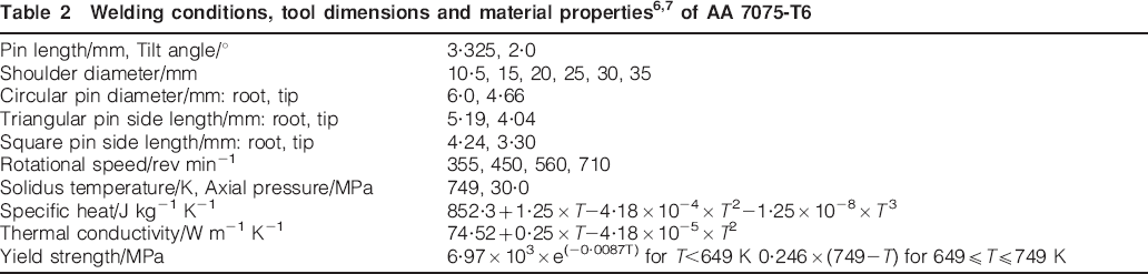
AA 7075-T6 plates of 3·5 mm thickness were machined to the required dimensions (172×97 mm) for the FSW experiments. The welding speed is kept constant at 0·67 mm s−1 for all the experiments. The tool material confirms to EN24 steel. Table 1 specifies the compositions of the workpiece and tool material. Table 2 depicts the welding conditions considered for the FSW experiments and the material properties of workpiece material. The plates were welded in a square butt joint configuration on a conventional vertical milling machine. The real time thermal cycles were monitored during each experiment using K type thermocouples at three longitudinal locations that are always 8·5 mm from the original weld interface in the transverse direction and at a depth of 0·75 mm from the top surface.
Compositions of workpiece (AA 7075-T6) and tool material (EN24)

The rotational and linear motions of the FSW tool are obtained by two three-phase ac induction motors, which are in built inside the milling machine. Figure 1a and b schematically depicts the set-up used for the online monitoring of torque and traverse force using the input electrical power and current of the corresponding driving motors that provide the rotational and linear speeds to the FSW tool. The rated electrical parameters of a three-phase ac induction motor can be calculated based on the basic operational principles as follows16


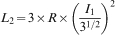


 for a star connected motor.16 The spindle and the feed motors in the FSW machine used in the current work are respectively delta connected and star connected. Increase in load enhances both the input current and power in a three-phase induction motor till a balance between the motor applied torque and the restraining torque due to the applied load is attained.16 Considering a linear torque vis-à-vis slip characteristic at low values of slip, the actual slip S2 and the spindle speed N4 can be estimated as S2 = (I2/I1)×S1 and N4 = N3×(1−S2) respectively.16 The actual output power of the rotor W6 and the motor W7 is estimated next as W6 = W5−L7 and W7 = W6−L5 respectively, where L7 = S2×W5.16 The spindle torque M and the traverse force F are finally estimated as


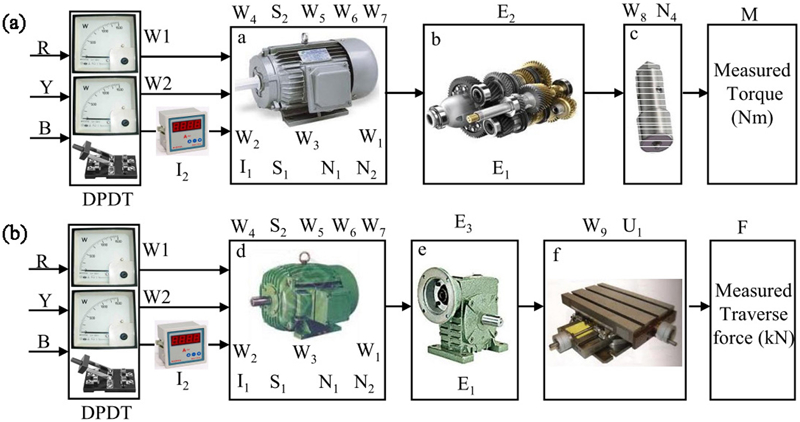
Schematic flow chart for online measurement of a torque and b traverse force (a: three-phase ac induction spindle motor; b: spindle gearbox; c: FSW tool rotated by spindle; d: three-phase ac induction feed motor; e: feed gearbox; f: machine table moved by lead screw); W1 and W2 represent wattmeters for power monitoring, and DPDT refers to double pole double throw switch; R, Y and B refer to three-phase supply; legends mentioned within box and atop box refer to corresponding rated parameters and actual parameters as defined in text
Nomenclature of symbols used in equations (1)–(13) and in Fig. 1
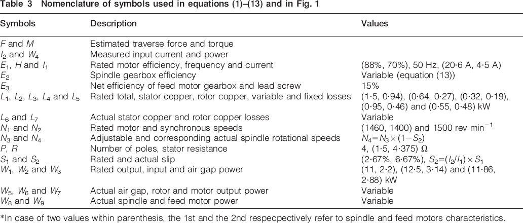
*In case of two values within parenthesis, the 1st and the 2nd respecpectively refer to spindle and feed motors characteristics.
Theoretical formulation
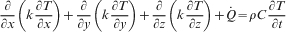
A transient three-dimensional heat conduction analysis of the FSW process is developed with the governing differential equation as17


Results and discussion
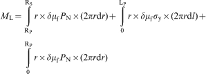
Figure 2 shows the experimentally measured and the corresponding numerically computed values of total torque during FSW of AA 7075-T6 with a rotational speed of 710 rev min−1 and at various tool shoulder diameters. The error bars indicate the uncertainty or variability in the measured torque over a specific length (∼50 mm) in the middle of the weld that typically confirms to a steady region and is further examined in three repeated tests for each welding condition. The specific length (∼50 mm) over which the measured torque is averaged has remained the same for all the welding conditions. The weld lengths are 154, 149, 144, 139 and 134 mm corresponding to the shoulder diameters 15, 20, 25, 30 and 35 mm. The torque increases with increase in shoulder diameter at a constant rotational speed that can be attributed to the monotonous increase in the sliding component of torque with the increase in tool shoulder diameter as apparent in equation (20). In contrast, increase in tool shoulder diameter will raise the sticking torque component, reaching to a point of inflection followed by a decrease with further increase in the shoulder diameter due to reduced flow stress of deforming material at higher temperature.6, 24 Similar behaviour of total torque with tool shoulder diameter is observed at other tool rotational speeds.6, 24
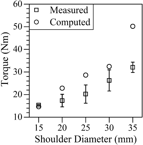
Comparison of computed and corresponding measured torque in FSW of AA 7075-T6 at various shoulder diameters with rotational speed of 710 rev min−1 and welding speed of 0·67 mm s−1 (tool geometry and welding conditions are specified in Table 2)
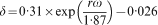
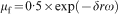
The discrepancy between the computed and the corresponding measured values of torque especially at the highest shoulder diameter of 35 mm can possibly be attributed to three factors. First, the reliability of the computed torque will depend on the presumed nature of the local variations in the fractional slip δ and the coefficient of friction μf (equations (18)–(21)). For a shoulder diameter of 35 mm and rotational speed of 710 rev min−1, rω equals to 1·3 m s−1, which is very close to its upper range (1·6 m s−1) of validity.6,7,24– 26 The fractional slip δ varies from 0·6 to 0·7 in the range of 1·3 to 1·6 m s−1, resulting in the predominance of the sliding component of torque that appears to be an artefact, and the presumed trend in the local variations of δ and μf especially at higher values of rω may need further examination. Second, the sliding component of torque increases with the axial force (equation (20)). In the present work, the axial force was measured in the static condition only due to the unavailability of sophisticated measurement system. The axial force often reduces during the actual welding due to thermal softening of workpiece material under the shoulder. A lower value of axial force would lead to reduced sliding torque in reality that has possibly remained as an artefact in the computed torque. Lastly, the thermal softening of workpiece material below the shoulder would also reduce the shear yield strength and, hence, the sticking component of torque (equation (21)). However, an appropriate estimate of the extent of the reduction in the sticking torque would depend on the reliability of the temperature dependent mechanical property. Although the temperature dependent yield strength of AA 7075 is considered from the past reference,6, 7 the reliability of the same especially at high temperature has always remained a critical issue. Since the peak temperature during welding with the shoulder diameter of 35 mm has reached well above 750 K, both the sliding and sticking components of torque might be overestimated due to the unlikely high values of axial force and shear yield strength respectively that could not be avoided in the computation in the absence of more practical measured values.
The numerical model is validated further with the independently reported values of measured torque as shown in Fig. 3 for FSW of 6·4 mm thick AA 2524-T351 at various tool rotational speeds with a tool shoulder diameter of 20·3 mm, pin diameter and length of 7·1 and 6·2 mm, and welding speed of 2·11 mm s−1.28 Figure 3 shows a decrease in torque with increase in the tool rotational speed. Increase in tool rotational speed enhances the rate of heat generation, resulting in higher peak temperature and softer workpiece material around the tool that leads to reduced torque. It is noteworthy that the torque in Ref. 28 has been measured using a comprehensive force and torque measurement system, while the same is measured from the input electrical power and current of the spindle motor in the present work. The fair agreement between the numerically computed and the corresponding experimentally measured values of torque in FSW of two different materials and at various welding conditions in Figs. 2 and 3 clearly indicates the efficacy of the torque measurement system and the reliability of the numerical model proposed in the present work.
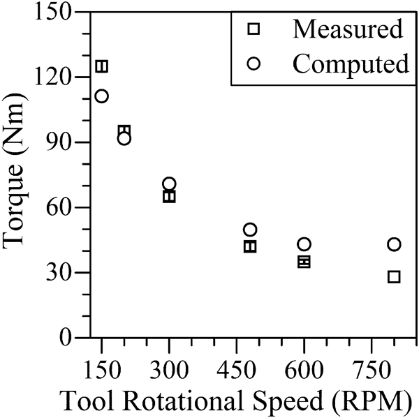
Comparison of computed and corresponding measured torque in FSW of AA 2524-T351 at various rotational speeds with shoulder diameter of 20·3 mm and welding speed of 2·11 mm s−1 (measured torques, welding conditions and tool geometry are considered from Ref. 28)
The numerical model proposed in this work is tested further with the corresponding measured values of peak temperature and thermal cycles in FSW of AA 7075-T6. Figure 4a and b depicts a fair agreement between the numerically computed and the corresponding experimentally measured peak temperature and thermal cycle respectively. Figure 4a depicts an increase in peak temperature with the increase in shoulder diameter at constant rotational speed. Increase in shoulder diameter leads to higher shoulder workpiece contact area, increased rate of heat generation and greater peak temperature. Figure 4b depicts a small offset between the computed and measured thermal cycle that can be attributed to the variation in the thermocouple positioning with respect to its original presumed location during the fixing of the thermocouple into the workpiece. Overall, a fair agreement between the numerically computed values of peak temperatures and thermal cycle, and the corresponding experimentally measured values further strengthens the reliability of the computed results.
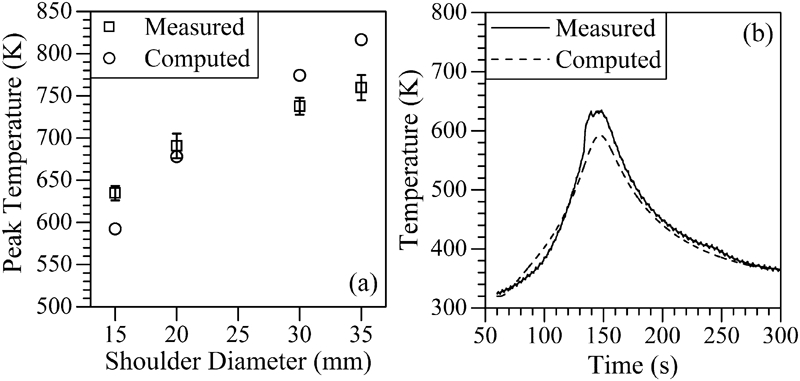
Comparison of computed and corresponding measured a peak temperature for various shoulder diameters at rotational speed of 710 rev min−1 and b thermal cycle for shoulder diameter of 15 mm and rotational speed of 710 rev min−1 during FSW of AA 7075-T6 (thermal cycle was measured at transverse distance of 8·5 mm from original weld interface and at depth of 0·75 mm from top surface)
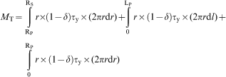
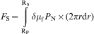
Figure 5 depicts the experimentally measured traverse force experienced by the tool during FSW of AA 7075-T6 at a rotational speed of 710 rev min−1 and tool shoulder diameter of 10·5 mm with circular, triangular and square pin profiles. The detailed tool geometry and other welding conditions are indicated in Table 2. The traverse force is measured using the electrical power and current of the corresponding feed motor, which provides the linear speed to the tool. The traverse force on the tool has increased from the circular to the triangular pin profile and then decreased for the square pin profile. For a given shoulder diameter, pin length and welding speed, the contact area between the tool pin and the deforming material increases from a circular to a triangular pin due to multiple sides and sharp edges. Increase in contact area between the tool pin and the deforming material in the case of triangular pin has led to increase in the traverse force in comparison to the same experienced by the tool pin with circular profile. The same is also apparent in equation (23). However, the greater number of pin sides is also expected to enhance the rate of plastic deformation and resultant heating, thereby softening of material that might be the reason for decrease in traverse force with the square pin profile. Also, the apparent contact area between the pin sides and deforming material decreases from the triangular to the square pin profile, with both confirming to the same circumcircle diameter [eq. (24)]. In short, for a given tool shoulder diameter, the traverse force on the pin would be influenced by the compound effect of contact area dA and the flow stress σy and average temperature of the deforming material in the proximity of the tool. The measured traverse force for circular profile was found to be of the similar order of magnitude for FSW of similar material.5 The numerically computed traverse force for the circular pin profile is in reasonable agreement with the corresponding measured value. The numerical model is further in progress so that the analysis of non-circular pin profiles can also be undertaken in the future.
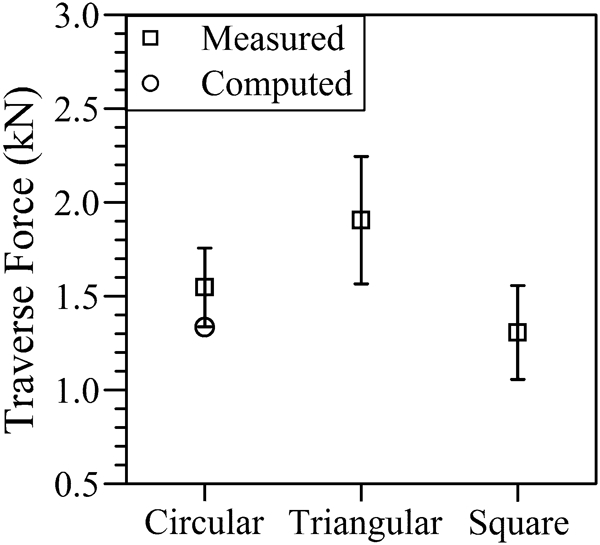
Comparison of computed and corresponding measured traverse force during FSW of AA 7075-T6 (traverse force was measured for circular, triangular and square pin profiles with shoulder diameter of 10·5 mm; computed result is shown for circular pin)
A simple, economical and reliable methodology is presented for the real time monitoring of the torque and traverse force from the input current and power drawn by the corresponding spindle and the feed motors that drive the rotational and linear motions of the FSW tool respectively. The measured values of torque are validated against the corresponding computed results from a three-dimensional heat transfer model for a wide range of welding conditions, while the traverse force is validated for circular pin profile in FSW of AA 7075-T6. The reliability of the model computed results of torque is checked with the corresponding measured values reported in independent literature28 so that the numerical model can serve as a premise to check the authenticity of the measured torque and traverse force in the present work.
Conclusions
An inexpensive and reliable methodology is developed to experimentally measure the torque and traverse force in terms of the input current and power of the corresponding spindle and feed motors that drive the rotational and linear motions of the FSW tool respectively. The proposed monitoring methodology is completely independent of change in welding conditions or in workpiece or in tool geometries since the set-up needs to measure the electrical power and current of the driving motors on the machine electrical panels. The monitoring set-up is used to measure torque for various tool shoulder diameters and rotational speeds, and traverse force for varying pin profiles during FSW of AA 7075-T6. The experimentally measured values of torque, traverse force and temperature are validated with the corresponding computed values from a three-dimensional numerical heat conduction model. The computed results of torque are also validated with corresponding independently measured values in FSW of AA 2524-T351. Further work is in progress to validate the measurement of torque and traverse force in FSW of different welding conditions and also to enhance the numerical model so that tools with non-circular pin profiles can be considered in model calculations.
Footnotes
Appendix
This paper is part of a special issue on computed-aided welding engineering