
Abstract
Recent economic and political events have further highlighted the need for new and strategically accessible sources of oil and gas. With the continually increasing demand for oil and gas, the requirement for pipeline steels with higher strength, toughness and weldability has been one of the most important factors driving the development of high strength pipeline steels, particularly with the oil exploration proceeding into arctic and deep sea regions, enhancing the weldability and mechanical properties of the new pipeline steels and weld consumables. Developments in the welding processes for manufacture and field welding are described in terms of process principles, equipment, consumables, weld quality, process economics and further developments. The increasing and changing requirement for weldability and mechanical properties in the heat affected zone and weld metal of pipeline welds are presented along with the reported solutions to the problems.
Introduction
Pipelines used for the transportation of crude oil or natural gas over long distance and under high pressure primarily require a combination of high strength and toughness, and good weldability for lowering transportation cost.1– 3 Particularly during the late two decades, the exploration of energy has expanded to cold regions such as northern Canada, the North Sea and Siberia.4 The higher grade steel pipes and enhanced weldability are being proposed for the purpose of enhancing the transport efficiency of pipelines. Thus, the investigation and development of improved and innovative welding techniques to face the new technical challenges is a major consideration in the pipeline industry.
This paper presents an overview of challenges and developments in the weldability of pipeline steels in grades from X70 to X120. The various welding processes for both the manufacturing of pipes and the construction of pipelines are evaluated. The mechanical properties of the base metal (BM), heat affected zone (HAZ) and weld metal (WM) in pipeline welds and the approaches to improve the toughness of the HAZ and WM are summarised.
Developments of high grade pipeline steels
The development and the changes in production techniques of high strength pipeline steels from 1990 to 2010 are shown in Fig. 1.5– 13 The chemical composition and mechanical properties of pipeline steel from X70 to X120 are given in Tables 1 and 2 respectively.8, 14, 15
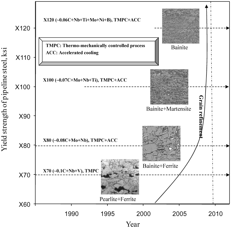
Development of pipeline steel grades and production techniques from 1990 to 2010
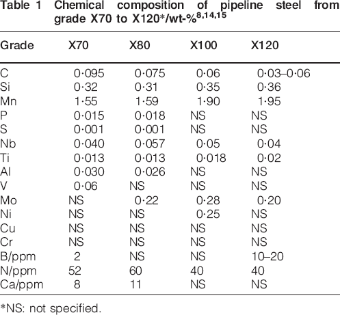
*NS: not specified.
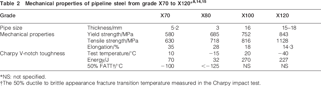
*NS: not specified.
†The 50% ductile to brittle appearance fracture transition temperature measured in the Charpy impact test.
It is seen that X80 steels instead of X60 and X65 are microalloyed with molybdenum, niobium and titanium, and the reduced carbon content has been developed and utilised for gas pipelines. A 163 mile, 48 in gas pipeline installed in 1992–1993 in Germany was the first to use X80 steel in the world. It thus has a higher design potential than the more widely used X70 because it allows system design with either thinner wall thicknesses at constant operating pressure or a corresponding increase in operating pressure.16 From the 1990s, the higher strength of X100 pipeline steels, having a further reduced carbon and a good combination of higher strength and better toughness (see Tables 1 and 2), compared with either X80 or X70 steels has been developed by an improved processing method, consisting of thermomechanically controlled process (TMCP) plus subsequent accelerated cooling (ACC). The aim of the TMCP process is to create an extremely fine grain microstructure by a skilled combination of rolling steps at particular temperature control. The grain in strength obtained by the grain refinement can reduce effectively the contents of both carbon and alloys in TMCP steel compared with normalised steel of the same grade. Thus, the weldability can be improved due to the leaner steel composition. For thick plates, an ACC after final rolling pass is beneficial for the achievement of the most suitable microstructure as it forces the transformation of elongated austenite grains before recrystallisation.3 The characterisation of prototypes of X100 pipes has been extensively studied by pipe manufacturers.7,17– 19 Further additions of Mo, Ni and B enable the strength level to be raised to that of grade X120 by the same processing method.9 To enable the development of remote gas sources in the future, higher strength pipelines such as X100 and X120 will play very important roles in the pipe industry.20, 21 It is also seen from Fig. 1 that the grain refinement is the key method by which both strength and toughness can simultaneously be improved. Generally, the ferrite grain of X70 steels (ASTM 10-11) is finer than that of X60 (ASTM 7-8).18 Changing the microstructure of the steel matrix from ferrite–pearlite to ferrite–bainite can attain further increases in strength and toughness, which leads to the development of X80 steel. It has been observed that the ferrite–bainite microstructure in X80 steel is more uniform and extremely fine with a mean grain size of <1 μm.22 However, this is still not the end. In order to significantly increase the strength above the X80 level, a fully bainitic microstructure with a very fine grain size has been aimed for X100 and X120 steels.
As applying the high strength steels, the materials used for pipeline can be saved greatly. The use of grade X80 pipeline in the construction leads to a materials saving of ∼20 000 t, compared with X70 pipes, through a reduction in the wall thickness from 20·8 mm for X70 to 18·3 mm for X80.23 The use of higher strength, such as grade X100 or grade X120, can result in further savings. For example, the X100 pipeline could give investment cost savings of ∼7% compared with grade X80 pipeline. This study claims cost savings of up to 30% when X70 and X100 are compared.24
Developments in weldability in X70 and X80 pipelines
In the early 1970s, grade X70 was introduced in the world for use as a pipe in the construction of gas transmission.25 Since then, there are satisfactory experiences to show that it can be welded trouble free with cellulosic electrodes providing care taken to avoid hydrogen induced cold crack.13, 25, 26 In summer 1994, a 33 km of NGT's Eastern Alberta system main line along the gas pipeline system operated in Alberta was the first North America long distance, large diameter pipeline to use X80 steel.27 Up to 2001, X80 pipeline was used widely in the world. Now, it becomes the basis of a standard platform for design and construction of large diameter pipeline projects in the network.
Achieving the balance between strength and weldability in the development of X70 and X80 has been a major consideration in respect of alloy design as indicated schematically in Fig. 2.14 The higher carbon equivalent (CE) values are obtained in the commercial X70 grade steels (Nb/V steel A and Nb/V steel B). Particularly, the Nb/V steel B provides little margin for pipe yield strength at a specified maximum CE per cent level of 0·39. An increase in CE to 0·40 allows for more comfortable achievement of strength but can be a questionable approach if heavier wall thicknesses are required from a weldability viewpoint. The application of Mo/Nb steel C in a subsequent X70/X80 provides for a good wide excellent strength at a considerably lower CE. The trend of X80 and X70 development is also indicated on the diagram, suggesting that the balance of strength/weldability also requires appropriate welding procedures for higher strength X80 pipelines for either metallurgical or economic reasons because of the changing of the alloying elements and the strength.
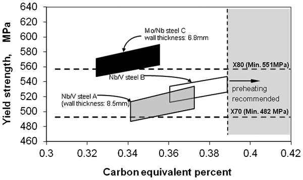
Influence of strength and weldability considerations on alloy design for X70 and X8014
Welding process developments for X70 and X80 pipelines
The pipeline welding can be divided into the following: manufacture welding and field welding. Good weldability of the steel used for the manufacture of pipeline is a prerequisite for trouble free welding in pipe laying. The field welding to be used has to meet requirements for maximum productivity and reliability.28, 29
The manufacture of large diameter pipeline involves the forming of plate to pipe, followed by seam welding and finally expansion of pipe to final shape. The seam welding operation is generally carried out using the high productivity submerged arc welding (SAW) process.30
Manual shielded metal arc welding (SMAW) process and mechanised gas metal arc welding (GMAW) process are two principal welding methods for field welding.15, 27, 31 These welding methods are well established now and regarded as sufficiently validated for large scale use. The method adopted depends on economic considerations: the most cost effective use of mechanised GMAW and manual SMAW depends on the type of mechanised welding system, the length of each individual construction and the topography of the land to be traversed.32
Submerged arc welding process
During longitudinal SAW seam process, the welded pipe is usually formed by a double SAW method, whose longitudinal butt joint is welded in at least two passes, one of which is on the inside of the pipe; the welds are made by heating with an electric arc between the bare metal electrodes. Pressure is not used. Filler metal for the welds is obtained from the electrodes. This process can penetrate the full thickness of the pipe because the heat input during the SAW is ≥2 kJ cm−1 per millimetre of thickness and gives a high productivity with good mechanical properties and a low repair rate.33– 35
The SAW welds in X70 pipeline are generally made with wire electrodes alloyed with Mn and Mo or with Mn, Mo and Ni.34– 39 The chemical composition of the wires is adjusted in such a way that the WMs, which contain 60–70%BM by dilution, exhibit maximum toughness. A proper balance between C, Mn and Mo contents as well as microalloying with Ti and B has a beneficial effect on WM toughness.6 Welding of X80 is carried out similarly using the same slightly basic agglomerated fluxes that have been well established for welding X70 line pipe steel. There are no needs of developing welding wires specifically for this material.38 Owing to reduced carbon content, X80 exhibits a slightly improved toughness in the HAZ compared with X70.29, 38
Since the high strength pipelines are welded by high heat input SAW process, the high heat input results in an increased grain size in the HAZ, and often leads to softening and a detrimental effect on the properties of the welded joint.2, 11 Jansen et al. 35 pointed out that this problem became even worse for the thin wall pipe due to the deep penetration of the second weld pass. Thus, pipe manufacturers have to take care of this by adjusting the chemical compositions of both BM and WM.
Manual SMAW process
Because of the high tensile strength of X80 pipe steel, it is not possible for the WM deposited by the cellulosic electrode used in X70 welding procedure to fulfil the requirement for the minimum tensile strength and to have simultaneously satisfactory toughness and resistance to cold cracking.25 Considerable changes have to be made to the manual SMAW method required in the construction of large diameter in high strength pipes. A combined electrode manual welding procedure has been proposed for use in X80 welding. This consists of making the root and hot pass welding with soft (lower strength grade) cellulosic electrodes, as in the case of X70, and the filler and cap passes with high strength vertical down basic electrodes (such as MAW type E55010 or AWS type E 10018-G) are used for both the root and hot passes. It is thus possible to ensure uniform progress during pipe laying.26, 39
Mechanised GMAW process
Besides manual SMAW, the mechanised GMAW becomes increasingly important as an economic process. For example, the SMAW process traditionally has been used to make the field girth welds; however, increasing use is being made of mechanised GMAW systems and for large diameter pipeline construction.40 The different steps in pipe welding with mechanised GMAW are shown in Fig. 3. It has several advantages over manual processes as follows: high metal deposition rates, a reduced gap, low hydrogen, consistency in both strength and toughness, very narrow welds, relatively low heat input with a variety of wires and gas shielding, and reduced welding time.25, 27 Unlike the 100%CO2 shielding gas used in GMAW for X70, the mechanised GMAW process for X80 requires the use of a principally inert gas shield, which greatly increases the notch and fracture toughness of the WM and virtually eliminates defects according to Price's investigation.40
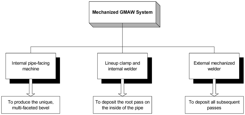
Diagram of mechanised GMAW process steps40
Even with the developments in mechanised GMAW, manual SMAW remains important in pipeline construction for repairing and future maintaining depending on the flexibility of this process. It should be carefully considered also in the case of frequent interruptions (road or rivers) where it may be more economical to apply manual SMAW welding.
Investigation of HAZ and WM in X70 and X80 welds
The mechanical properties of both HAZ and WM play very important roles for the use of pipeline welds. Generally, the joint is constituted of three different regions: WM, HAZ and BM. If the failure occurs in the WM, the material will not be approved since it is designed to have higher strength than BM; if failure occurs at the HAZ, it is said to be embrittled. Therefore, the best result for a joint is when the failure occurs in the BM rather than either WM or HAZ.41 In such high strength pipeline, excellent toughness in the HAZ and WM is required to arrest a running shear fracture and to prevent brittle fracture for improving the installation efficiency. Thus, the possibilities of improving the toughness of HAZ and WM with increasing strength of pipeline have received extensive investigations.42– 47
Heat affected zone
For a typical X80 pipeline, the resulting microstructure of the commercial alloy is one containing ferrite and bainite (see Fig. 1). This microstructure can increase the strength without significant losses of toughness. However, the excellent combination of strength and toughness can be greatly degraded by the thermal cycles imposed during the fabrication of the final pipeline product and its onsite assembly for service. On one hand, welding processes impose cycles that can lead to intercritical coarse grain regions to form local brittle zones in the HAZ.5, 41 On the other hand, the microstructure of the HAZ changes from martensite to lower bainite, upper bainite and then to ferrite and pearlite, as the heat input at welding increases, or the rate of cooling decreases.41, 48, 49 Especially, the low temperature toughness will deteriorate when the microstructure consists of hard martensite–austenite (MA) islands. Figure 4 shows that the reduction in toughness is dependent on the volume fraction of MA present.50 The crack tip open distance (CTOD) value decreases with the increasing volume fraction of MA. Thus, the initial balance between strength and toughness in the BM can be lost in the HAZ of the weld.
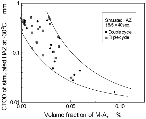
Dependence of reheated HAZ toughness on volume fraction of MA50
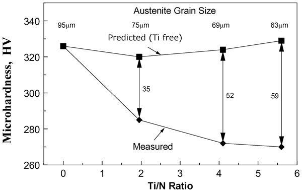
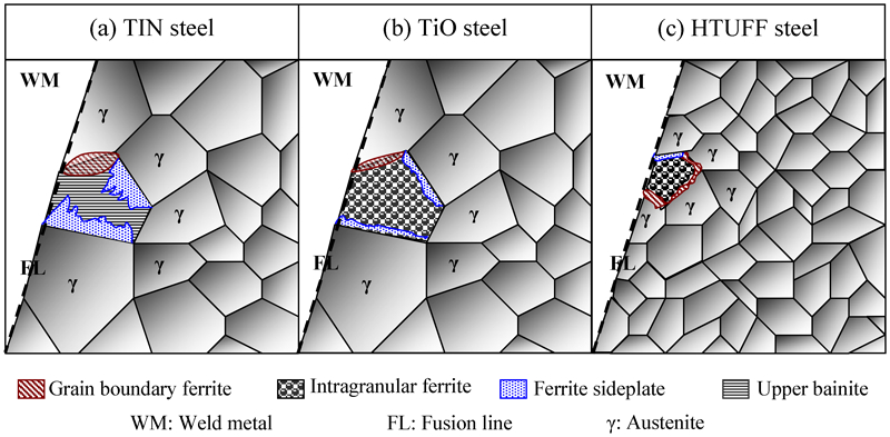
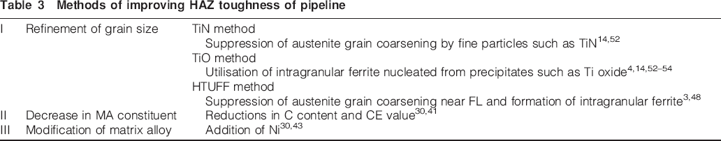
High or ultrahigh heat input (about 300–1300 kJ cm−1) in highly efficient welding technologies to reduce the fabrication cost has recently been widely applied in pipeline industry.2, 11, 28, 44 It is easy to form coarse grain microstructure and MA constituent in HAZ after such ultrahigh heat input welding. Since grain coarsening and the MA constituent present in HAZ structure are the main reasons for toughness deterioration in the weld area, a fine microstructure and reduced formation of MA will lead to improve the HAZ toughness in X70 and X80 pipes.35, 41, 48 Three main methods have been advanced to increase the HAZ toughness, which are summarised in Table 3. The first method used titanium as TiN has been utilised in pipeline steels to improve the HAZ toughness. It is also clear from Fig. 5 that the hardness of the HAZ can be reduced by austenite (γ) grain size refinement from 95 to 63 μm, which is controlled by the adjustment of Ti/N ratio. This result cannot be obtained in the predicted Ti free steels (also shown in Fig. 5).14, 51 However, this method is not always satisfactory in the refinement of γ grain size because the TiN particles coarsen or disappear near the fusion line (FL) where the weld is heated to 1400°C or higher, and, as a result, their effect to inhibit the coarsening of γ grain is lost (see Fig. 6a).3, 35, 48
Methods of improving HAZ toughness of pipeline
Under these circumstances, a new technology has been developed where fine TiO particles dispersed in steel are utilised (TiO steel).3,52– 54 In a TiO steel, TiO particles existing inside a γ grain serve as nuclei of intragranular ferrite (IGF). The IGF forms around the TiO particles, and as a result, coarse γ grains are divided into fine ferrite grains to give excellent HAZ toughness (see Fig. 6b). On the basis of this, an innovative HTUFF technology has been developed by Terada et al.48 In the steel based on HTUFF, the coarsening of γ grains near the FL is suppressed by pinning particles of oxides, and the IGF forms inside them. As a consequence, the microstructure of the HAZ is made remarkably fine (see Fig. 6c). The average size of γ grain in HTUFF pipe steel is much finer (200 μm) than that in TiO pipe steel (500 μm). The HAZ of toughness of the HTUFF steel under X80 is superior to that in the conventional TiN steel.
The MA volume fraction is related to the carbon content.30 It was shown from the research result of Bott et al.41 that the volume fraction of MA in HAZ of X80 (Nb–Cr–Mo) pipeline steel was increased from 7·3 to 8·3% as the carbon content increased from 0·04 to 0·07 wt-%. It was also observed that the volume fraction of MA increased with increasing CE. For the same level of carbon content of 0·04 wt-%, the volume fraction of MA in NbCrMo X80 pipeline steel was 1·4 times as high as that in NbCr X80 pipeline steel because the formal steel has a higher CE. For pipeline steels, there is a general ‘shift’ of toughness values depending on the extent to which the microalloying additions contribute to grain size refinement of the HAZ. Fracture appearance transition temperature (FATT) is the temperature for which the fracture surface of the broken Charpy specimen exhibits 50% brittle and 50% ductile morphologies. Various microstructures and different chemical compositions influence the FATT values. This effect is particularly noticeable in the HAZ of weldments.18, 22, 46 It was shown from Fig. 7 that the FATT value in HAZ decreased with increasing Ni content from 1 to 5 wt-%. Ni additions in excess of ∼3% would shift the upper bainitic transformation range to longer cooling times, as a result of which favourable transformation conditions would be achieved in the cooling time range.40
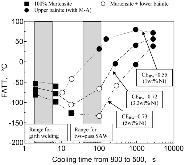
Correlation between FATT and cooling time for coarse grained HAZ microstructures of pipeline steels40 [CEIIW = C+Mn/6+(Mo+Cr+V)/5+(Cu+Ni)/15]
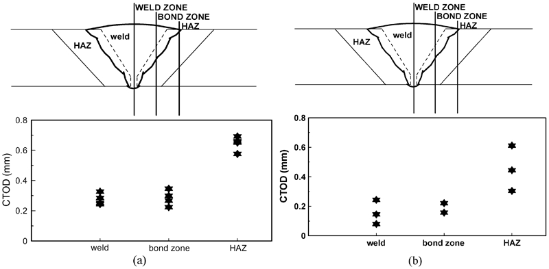
It was apparent from Fig. 8a that the most susceptible region to cracking was not the HAZ but the WM in X70 grade, no doubt reflecting the enhanced weldability of the pipe.14, 55 These steel characteristics also provided the added benefits of the high fracture toughness in the HAZ of field welded X70 pipeline. The higher CTOD value in HAZ was also obtained as in field welded X80 line pipe (see Fig. 8b). However, it was evident that WM toughness was inferior to that recorded in the X70 field welding. This can be attributed to the increased WM strength (E9010) employed in the X80 trials. From the above results, it can be seen that the low toughness problem is displaced from the HAZ to the WM with the increasing strength of pipeline steel. Thus, the improvement of the WM toughness is becoming more important for the higher strength pipeline steels.
Weld metal
The relationships between the WM microstructure, composition and welding conditions are even more complex than in the HAZ. This is because, while all the factors discussed above come into play, the chemical composition of the WM and its macrodistribution in the solidified weld pool are functions of the BM and consumable compositions, the flux activity and the welding process variables.
Specified minimum strength requirements for pipelines and currently available cellulosic consumables are shown in Fig. 9.55 It is seen that with the introduction of X80 pipeline, the maximum available cellulosic consumable strength level is now marginal with respect to strength matching for the pipe. Studies have shown that overmatching the WM strength causes gross section yielding in the pipe; undermatching the WM strength will cause straining of the weld.40 Generally practice in industry is that the welding WM overmatches the pipe yield strength.23 However, this can lead to some undesirable results when applied to higher strength pipe, such as X80. First, with SMAW with cellulosic consumables, the weldability decreases as strength increases, which will result in the potential for more defects. Since the higher strength electrode will be more susceptible to cracking, it will certainly promote WM cracking. Second, the defects could be of the more deleterious planar type, including hydrogen cracks. Third, toughness usually decreases with increasing strength.27, 40, 56 Therefore, the development of SMAW procedure for X80 pipelines is a greater challenge than for GMAW because of the difficulty in selecting consumables to match strength and toughness while maintaining good productivity and acceptable weld quality.
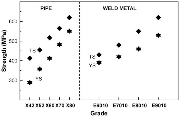
Specified minimum strength requirements for pipe and currently available cellulosic consumables55
Two major approaches have been pursued to improve the toughness of the WM in SAW process. One is to use different types of fluxes/wires.57, 58 The other of great interest is to alter WM composition either through the use of newer filler metals or by metal powder additions in the WM.59– 63 Many of the basic microstructural principles that apply to the HAZ are also valid with respect to the WM. However, an additional important microstructure is acicular ferrite (AF), consisting of fine interlocking grains, which is associated with good toughness. The formation of AF depends not only on a suitable combination of alloying elements and cooling rate but also on the existence of an appropriate distribution of inclusions.64– 66
It is well known that Ni and Mo in the WM play important roles in microstructural control.67, 68 However, there is no general agreement regarding the optimum amount and combinations of Ni and Mo in the WM. Ni can be either detrimental or beneficial to impact toughness. It has been reported that the WM toughness can be increased markedly by an increase in Ni content.69 However, some investigations have shown that the benefit from Ni is conditional. Keehan et al. found that once Ni exceeded a critical point, which depends on Mn concentration, the Charpy toughness at −40°C decreases.70, 71 Shankar and Devletian61 found the toughness decreased due to Ni increasing in Fe–Ni alloys but could be better in Fe–C–Ni ternary alloys related to composition in terms of a variable coefficient for C in the Ni equivalent. It was reported by Evans72 that the best impact toughness occurred at <0·5 wt-%Mo in a controlled manner with respect to Mn. Thuvander et al. 73 showed that significant amounts of Mo offered excellent properties in WMs in a highly alloyed steel. The addition of Mo and Ni together has been reported to harden the WM and therefore decrease the impact toughness.74 On the contrary, Snyder and Pense75 found an improvement in impact toughness by introducing 0·42 wt-%Mo and 0·84 wt-%Ni in WMs. It was shown by Bhole et al. 37 that the addition of Mo in the range 0·817–0·881 wt-% resulted in a decrease in FATT and an increase in impact toughness in X70 pipe steel. It was also found that the combined presence of 2·03–2·91 wt-%Ni and 0·75–0·995 wt-%Mo in the WM led to a high volume fraction of fine AF with good toughness (see Fig. 10).
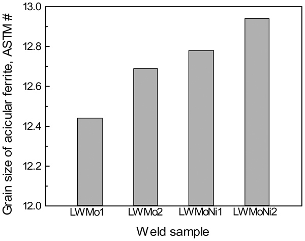
Grain size of AF of weld samples37 [LWMo1 (0·75 wt-%Mo); LWMo2 (0·90 wt-%Mo); LWMoNi1 (2·03 wt-%Ni, 0·995 wt-%Mo); LWMoNi2 (2·99 wt-%Ni, 0·75 wt-%Mo]
Figure 11 shows the chemical composition of the longitudinal seam WM deposited by the two pass SAW method in X80 grade pipe plate with the thickness of 18·3 mm [the chemical composition of X80 steel is 0·09C–1·9Mn–0·02Nb–0·02Ti (wt-%)]. Also shown in the figure are the impact energy values measured at 0°C.26 The WM has a high Mn content and is additionally alloyed with Mo. This Mn–Mo WM represents a good compromise with respect to toughness and mechanical strength. The average impact energy value measured varied between 100 and 200 J, which is higher than that (∼95 J) of the BM. Therefore, the weldment breaks in the BM, which is outside the weld region. It is said that the beneficial effect of Mo is due to the formation of predominant AF and granular bainite, at the expense of ferrite with second phase and grain boundary ferrite in the WM.37
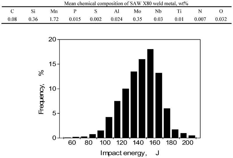
Mean chemical composition and distribution of impact energy values for SAW longitudinal seam WM for X80 pipe26
Careful control of the flux is beneficial controlling the WM toughness. In welding high strength pipe steel using the SAW process, neutral Al basic or fluoride basic fluxes are the only options. With higher strength, the lowest diffusible hydrogen content level is preferred. Usually, the use of a certain flux is necessary to control the oxygen content of the weld deposit in relation to aluminium (Al) content of the BM (dilution).35, 76
As proposed by Peng et al.,65 the chemical compositions of wire for the SAW of higher strength pipeline steel are designed according to the following requirements:
the WM mainly consists of AF
microalloying elements are added to increase the strength and toughness of the WM, and to produce particles of high temperature stability
the wire is purified to decrease the content of S, P, H, O and N
low carbon content is adopted.
Typically, solid wires are used when the SAW process is applied. The chemical composition of these solid wires also includes Mn, Ni, Mo and Cr in some cases. Today, cored wires (metal core) are more often used for increasing the deposition rate.39 The most important issue from a manufacturer point of view is the possibility of making any desired alloy and choosing flux/wire combination in order to obtain a satisfactory weld.35
In summary, X80 is becoming more popular pipeline than X70 in the pipe industry, since it is more economical. With the development of welding processing methods and further optimisation of the TMCP treatment, consistently predictable and reproducible mechanical properties and good field weldability can be achieved without difficulty.
Developments and challenges of weldability in X100 and X120 pipelines
The natural environment of resource development sites has become more severe with the increasing demand for oil and gas. As a consequence, increasingly sophisticated and diversified properties are required for pipelines, such as shown in Fig. 12.4 Hence, the development of higher strength steels has intensified worldwide. As the development of grade X80 matures, this grade is now state of the art application for high pressure gas pipelines. Grade X100 has currently reached the stage of full scale testing. Some pipe manufacturers have produced large diameter pipes in grade X100 on a commercial scale for extensive research.28, 58 In the case of X120 grade steel, some companies8, 9, 77 have developed a basic concept for manufacturing and using the steel for high pressure gas pipelines. In February 2004, a pipeline was laid in Canada under frigid conditions using X120. Since higher grades like X100 and X120 are not yet specified in the current line pipe standards such as API 5L, a lot of investigations have to be established by correlation with the minimum specified yield strength and tensile strength of X70 and X80.8 Welding procedure specifications using existing welding technologies for producing welded joints with good toughness and strength have been designed and studied extensively.7– 9,12,15,20,21,24,31,78
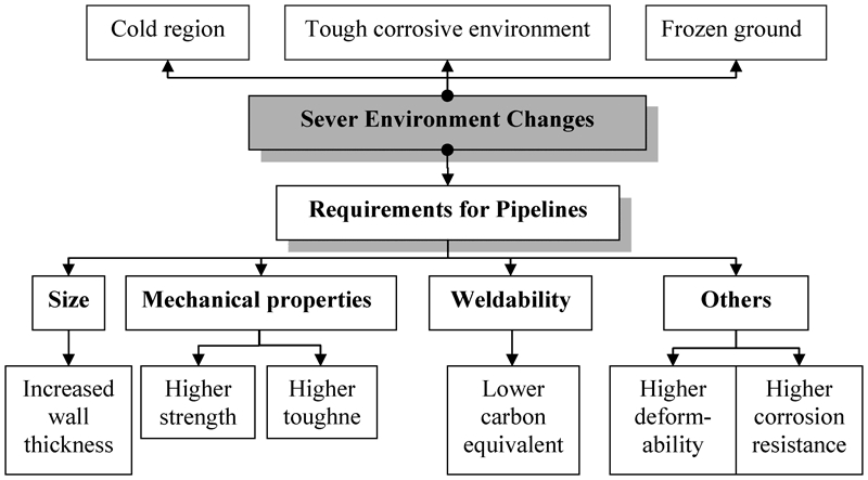
New requirements for pipeline for oil exploration4
Welding processes challenges for X100 and X120 pipelines
A significant challenge in the deployment of higher strength pipeline such as X100 and X120 is the development of welding technology that is compatible with existing pipeline manufacture and construction methods. Successful welding of high strength pipeline requires sufficient hydrogen cracking resistance, good welding productivity and ease of welder use, while maintaining the proper balance between strength and toughness.20
Longitudinal seam welding technology
In order that as many existing production facilities as possible can be used for the production of X100 and X120 pipelines, the multiwire SAW welding process with a high heat input used to deposit the two-pass longitudinal seam weld in pipe has been adopted for the longitudinal seam welding of X100 and X120 pipes.9 However, there are two problems emphasised by Gräf et al. 15 First is the softening of the BM beside the longitudinal seam weld. This problem also exists in grade X80 but can be easily managed. Production experience available today is not sufficient to permit an assessment of the softening that occurs in the BM beside the weld. To advice this aspect, the X120 pipe steel contains some amount of V for its precipitation hardening effect.8 Second is continuing the use of the proven SAW and achieving adequate strength and toughness for the WM of two-pass longitudinal seam weld in the higher strength X100 and X120. The new high strength and high toughness WMs for SAW have to be developed. Any conventional consumable cannot be used for either X100 or X120 pipe because the strength equal to or higher than that of the BM is required in the WM of the seam weld. This problem cannot be resolved by simply electing a matching chemical composition for the consumable alone. It would be rather necessary to reduce the heat input per pass. From the view of production safety, it is impossible to reduce the heat input with two-pass SAW to the extent necessary.
Field girth welding technology
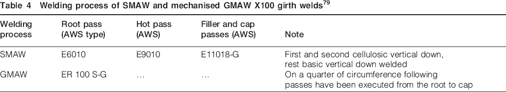
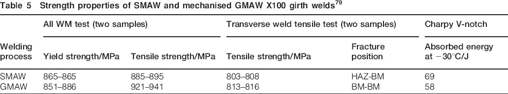
Manual SMAW and mechanised GMAW field welding of high strength pipeline in grades X100 and X120 do not pose any severe problems.7, 15 From the results of Barsanti et al. given from Tables 4 and 5, 79 it can be seen that the WM of SMAW weld deposited in the vertical down position, in combination with softer root pass welds, has sufficient strength to achieve the strength specified for the BM of X100. The GMAW weld also shows enough tensile and yield strengths compared with the BM. Both WMs of SMAW and GMAW welds exhibit sufficiently high Charpy V-notch impact energy at −30°C. It is also clear that besides the manual vertical down SMAW methods, the mechanised GMAW techniques are very promising considering the fact that this technique will be much more involved in the applications suitable for X100 steel grade and above under the situation of long distance natural gas transportation over large diameter and high pressure. It is also said that the X100 and X120 pipes produced respond favourably to manual SMAW and mechanised GMAW field welding due to their reduced carbon contents.
Welding process of SMAW and mechanised GMAW X100 girth welds79
Strength properties of SMAW and mechanised GMAW X100 girth welds79
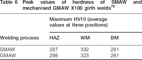
It should be noted that cold cracking is a typical problem associated to high strength pipeline welding.7, 8, 15 Table 6 shows that it is not the BM but the filler WM (with the highest maximum hardness) deposited with ultrahigh strength electrodes that is more sensitive and, therefore, plays the major role with regard to avoiding cold cracking in grade X100. The preheat temperature must be appropriate to the WM chemistry and the hydrogen input during welding. Barsanti et al. 79 suggested that using a preheat temperature of 100–120°C would be sufficient for hydrogen to adequately diffuse from the ultrahigh strength basic WM in the filling and cap passes before the weld cooled down to room temperature. This is also the case for X120 field girth welding. This is because, in girth welds, which are characterised by cooling times of t8/5 = 2–6 s, the peak hardness of the root pass HAZ is due to a 100% martensitic microstructure and dependent on the carbon content rather than the CE. Thus, it is seen from Fig. 13 that there is no difference in the HAZ cold cracking behaviour in the range of girth welding between X100 and X120 pipe steel.15
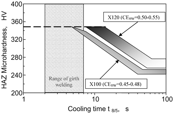
Hardenability of pipeline steel X100 and X12015 [CEIIW = C+Mn/6+(Mo+Cr+V)/5+(Cu+Ni)/15]
Peak values of hardness of SMAW and mechanised GMAW X100 girth welds79
Investigation of HAZ and WM in X100 and X120 welds
Heat affected zone
The possibilities to improve the HAZ toughness of longitudinal seam weld have been widely discussed.38, 48, 80 It is difficult to improve the HAZ toughness of a X100 and above pipeline steel by conventional microstructure refining technologies because of the presence of the detrimental MA in the HAZ of such steels. It has been reported by Terada et al. 48 that the most effective method for improving the HAZ toughness of either X100 or X120 pipeline would lower the carbon content. Figure 14 shows that under the single cycle condition as well as the double cycle condition, the simulated HAZ Charpy V-notch value tended to increase when C content decreased to 0·04 wt-% or less. Under the double cycle condition, the MA formed in great amounts at the boundaries of prior austenite grains when the C content was high, but the amount of the MA decreased drastically when C content was ≤0·04 wt-%. The improvement of HAZ toughness is attributed to the decrease in the formation of the MA.
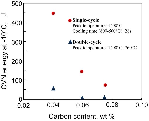
Effect of carbon content on simulated HAZ toughness of X100 pipe steel48
It was mentioned by Bott et al. 41, Ouchi81 and Li et al. 82 that the deleterious effect of MA on HAZ toughness was not only associated with MA volume fraction but also with its morphology, size and distribution in the matrix. They also found that the MA particles with small average size resulted in not very low HAZ toughness in SAW X80 welds.
The preexisting welding technology is modified and optimised by reducing the heat input of each pass as mentioned in this paper. A low heat input welding process leads to a minimisation of the softening of the HAZ in combination with an improvement in its toughness.8 However, the potential for rapid cooling of the weldment increases its susceptibility to formation of hard, brittle microstructures in the grain coarsened HAZ of the weld, microstructures that increase the risk of hydrogen assisted cold cracking.46 Wu et al.47 attempted to overcome this problem by controlling the fast cooling process with holding time above Ac3 and the cooling time from 800 to 500°C. They found that the shorten holding time led to thinner HAZ width and finer austenite grains in the FL and coarse grained HAZ, while the decreased cooling time from 800 to 500°C resulted in finer bainitic ferrite in the HAZ.
The low carbon content in conjunction with a relatively high CE has been found to be optimum with respect to reducing the softening of the HAZ, which gains in significance as the pipeline steel grade increases to X100 and X120.48, 79
Weld metal
Okaguchi et al. 21 suggested that WM toughness and hydrogen cracking were expected to be the primary challenges for grades X100 and X120 welds. Particularly for X120 application, since the AF is likely to be too weak, the martensite, bainite and/or their derivatives should be the primary WM components.9, 21 Therefore, the design of the chemical composition of the WM to obtain the desired microstructure for adequate strength and toughness to match BM is a major consideration.
The WM properties reported by Hillenbrand et al. 83, 84 for X100 pipelines show that both the conventional C–Mn–Mo and C–Mn–Mo–Ti–B WMs result in adequate toughness and strength of the X100 weld. The almost fully AF with an ultrafine grain size (1–2 μm) leads to the optimum strength and toughness obtained in Mo–B–Ti alloyed WMs.1 Some experimental work has been carried out to develop a new WM for the longitudinal seam weld of X120, given in Table 7.8, 9 It is possible to obtain a WM that yields a combination of strength of roughly 1000 MPa and a high toughness by appropriate design of the chemistry (Mn–Ni–Mo–Cr) of WM in grade X120.
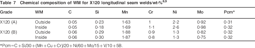
*Pcm = C+Si/30+(Mn+Cu+Cr)/20+Ni/60+Mo/15+V/10+5B.
X100 pipeline has been developed, and the characterisation of prototype pipes has been extensively studied by pipe manufacturers and major oil companies. Further development is required to extend grade X100 to higher pipe diameters and lower design temperatures. During the current development, the heavy plate rolling and pipe production as well as processes for longitudinal seam welding are modified or even completely newly developed with respect to the new high strength grade X120. Furthermore, new welding consumables and low heat input welding technology have to be developed to avoid typical problems associated to X120 microstructures and chemical compositions, namely, cold cracking, weld joint toughness and hydrogen susceptibility.
After extensive developments, the X100 and X120 options appear to be mature from the technological point of view. Although the welding processes have to be modified or even developed with respect to them, it is to be expected that both X100 and X120 pipelines will be increasingly used in the incoming years.
Latest developments and challenges of non-conventional welding technology
The arc welding processes have been applied for pipeline welding of oil and gas for many years. However, with an increasing demand for high strength steels for pipeline applications, some novel welding techniques have been investigated to achieve higher quality welds and more efficiency operations compared to conventional SMAW and GMAW.28,44,58,85– 88
Electron beam welding (EBW) and laser processes have been introduced into pipeline industry recently. The advantages of both processes are an extremely high power density and thus a low heat input. The EBW is a mature welding process, in which the gun can rotate along the horizontal direction and move inside. It offers many advantages in terms of weld productivity, avoidance of distortion and minimal metallurgical disturbance. However, the necessity to weld in a high vacuum atmosphere has restricted the application of the process to components and structures that can be entirely contained within a vacuum chamber.28, 44 Hybrid laser arc welding (HLAW) is a combined process of GMAW and laser beam welding, which improves the absorption of laser energy in GMAW weld pool as well as the arc stability due to laser induced ionisation. Hybrid laser arc welding allows welding to be performed at higher travel speeds, with greater penetration and reduced distortion than conventional arc welding processes. It has been demonstrated that the improvements in weld microstructures and WM toughness are possible using the HLAW process.85, 86 Although HLAW is a productive and advantageous welding process, there are certain limitations that restrict its use such as expensive laser equipment.
Recently, FRIEX, a new variant of the well known friction welding process, has been developed for use in pipeline welding. A welding ring is placed in between the pipes, and rotating the ring under an axial pressure generates the required friction heat during welding. It greatly reduces distortion and eliminates solidification defects.28, 58 Because the joining takes place below the melting temperature, the better quality weld can be created with low heat input, minimal distortion, no filler material and no fumes. Despite extensive development efforts on pipe grads from X70 to X120, this process has so far failed to archive widespread benefits for pipeline construction due to the need for a better understanding on the role of process parameters on microstructural evolution and weld quality.87, 88
The main advantages of using these welding techniques instead of conventional arc welding processes are to reduce the number of passes at constant and to improve weld quality. Although they have shown promise for field pipeline construction, more research and development is still being required to optimise the processes and to balance cost for a practical industrial application.
Conclusions
During more than two decades of developments, X80 is becoming a more popular pipeline than X70 in the pipe industry. The use of X80 causes no problems with respect to mechanical properties and welding. Recent market requirements for enhanced pipelines with higher strength, larger diameter, greater operating pressure and reduced cost have led to new high grade pipes, such as X100 and X120. With regard to the arc welding of X80 pipelines, the challenge for welding X100 and X120 is even more significant. The following main challenges need to be addressed for the high strength steels including X100 and X120.
First is to develop appropriate welding procedures.
The strength softening in the HAZ and the low HAZ toughness at the FL boundary are two weakest links for the SAW of high strength pipe steels, which are attributed to the high heat input between BM and WM in SAW process. The major challenge during girth welding of X100 and X120 is how to avoid cold cracking that resulted from WM deposited with ultrahigh strength electrodes. Therefore, the existing welding techniques have to be optimised and a low heat input welding process has to be developed.
Second is to produce WM with suitable mechanical properties.
The WM should overmatch the minimum yield strength of the BM of either X100 or X120 and provide the considerable satisfactory levels of toughness even at low temperatures simultaneously. However, based on current technology, it is difficult for WM to fulfill the existing requirements at the same time. Commercially, such WMs are not yet available and need to be designed and developed.
The novel welding techniques including EBW, HLAW and FRIEX have now been developed to a stage where they present opportunities for cost savings, which arise from reductions in labour content. However, a wide range of implementation of these new processes has been limited for its popular applications for different reasons.