
Abstract
In the present work, we design a novel tool called self-support FSW (SSFSW) with adjustable dip angle to join the aluminium hollow extrusion. This tool consists of a big concave upper shoulder and a small convex lower shoulder. Compared with conventional FSW, it eliminates root flaws and does not need backing bars during operation. In particular, the SSFSW can adapt to variation of thickness and does not need predrilled pilot holes, resulting in simplifying the welding process compared with the bobbin tool FSW tool. Significant changes are observed at the cross-section of the SSFSW joint, which looks like a ‘waist’. The average tensile strength and elongation of 6005A aluminium alloy joint with a thickness of 5 mm is 190 MPa and 6·86% respectively. Furthermore, the failure of specimen presents a ductile fracture in the typical joint.
Keywords
Introduction
The railway vehicle bodies made of aluminium hollow extrusions, integrating the functions of beams and plates because of its high rigidity, are now getting popular to reduce their weight and improve their environmental impact.1 On the one hand, the use of lightweight aluminium alloy can significantly reduce the vehicle's weight, resulting in reduced fuel consumption, which accounts for >99% of a railway vehicle's life cycle energy.1 On the other hand, the use of double skinned structure shortens the length of the welding line because the extrusions are aligned longitudinally and provides greater flexibility in the choice of cross-section of the car body.2
Mental inert gas (MIG) arc is commonly used to join the aluminium alloy components of the bodies. However, the high temperature generated by MIG welding creates large deformation during welding. The friction stir welding (FSW) is a solid state welding process invented and patented by The Welding Institute in 1991.3 It offers an alternative to conventional fusion welding processes providing a variety of excellent properties.4 The FSW technology is currently applied to the construction of double skinned railway vehicles made of hollow aluminium extrusions. However, it presents some limitations: to generate a force to react against the welding tool pressure load, it is necessary to have a device of high rigidity and profiled backing bar to achieve conventional FSW successfully.5 Root flaws due to a lack of tool penetration are possible to exist.6
The bobbin tool FSW (BTFSW) has been successfully used for many years in Japan for industrial fabrication of railway cars. In recent years, the development of BTFSW technique was undertaken by EADS CRC-F.5 The BTFSW has great potential to be a valuable high productivity manufacturing technique for structures of interest to the transport industries, offering high quality, highly repeatable welds at a competitive cost.7 A bobbin tool consists of two parts: the upper shoulder and the pin act similarly to the standard FSW. The lower shoulder attached to the tip of the pin contacts the opposing surface of the workpiece.8 The BTFSW is effective for joining hollow extrusions and lap joints.9 Essentially, there are two types of bobbin or self-reacting techniques: technique of a fixed gap, between the shoulders and one that allows the gap between the shoulders to adapt during the welding operation.10 The Group Sponsored Project has designed two kinds of floating bobbin FSW technology: pinless floating bobbin FSW and one piece floating bobbin FSW. The pinless floating bobbin FSW was demonstrated on welding 3 mm thickness AA 6082-T6 and the one piece floating bobbin FSW achieved good quality welds in 3 mm thickness AA 6082-T6.11 The BTFSW appears promising for the joining of double curve fuselage components and the lightening of the welding clamping tool.12 However, BTFSW needs predrilled pilot holes during welding and has a risk of pin breakage when the welding energy is too low, and welds present lack of consolidation defects when the travel is too fast.6
In the present work, a new self-support FSW (SSFSW) tool with adjustable dip angle (the angle between tool centre axis and vertical line) is designed to join the aluminium hollow extrusion. The SSFSW consists of two shoulders: the concave upper shoulder and the smaller convex lower shoulder. Particularly, the SSFSW can adapt to the change of thickness of the plate and no predrilled pilot holes are required during operation. The aim of this paper is to introduce the SSFSW technique for hollow extrusion.
Experimental
The materials used are 6005A aluminium alloy plates with dimensions of 5×350×80 mm. The chemical compositions and mechanical properties of 6005A aluminium alloy are listed in Table 1. The SSFSW tool consists of double shoulders: the upper shoulder, the lower shoulder and tapered stir pin made of high speed tool steel, as shown in Fig. 1. The angle between the upper shoulder and tool centre axis is 80°, and the angle between the lower shoulder and tool centre axis is 75°. The diameter of the lower shoulder is much smaller than that of the upper shoulder so that the tool can be directly pressed into the workpiece and the predrilled pilot hole is not required. At the same time, the reduction in lower shoulder diameter results in lower frictional contact and resistance, therefore less torque and bending moment.13 The upper shoulder is indent. However, the lower shoulder is convex so that the dip angle can be adjusted. The SSFSW processing can be performed using an FSW machine (FSW-3LM-003). The geometries and features of the SSFSW tool are listed in Table 2.
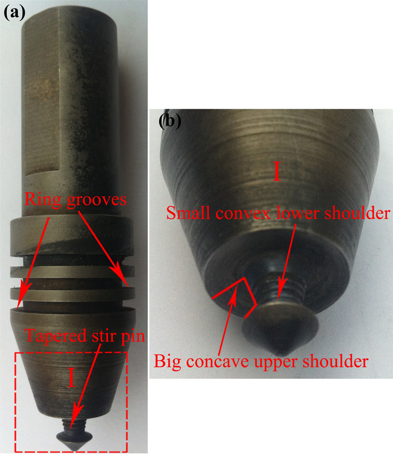
Photos of new FSW tool
Chemical compositions and mechanical properties of 6005A aluminium alloy
Welding tool geometries and features for SSFSW

To test the effect of SSFSW tool on joining of aluminium hollow extrusion, the plates are fixed on the clamping apparatus without backing bar. The tool is pressed into the plates at the edge and starts to weld with 30 mm min−1 welding speed to avoid the risk of pin breakage. Then, the joining is operated with the preset welding parameters.
The standard tensile samples of the joint were cut using super computer numerical control wirecutting machine according to the national standard GB 2625-89 welding joint tensile test methods. The room temperature tensile test is performed at a crosshead speed of 1 mm min−1 at an Instron-1186 universal testing machine. Macrostructure of joints is characterised by optical microscopy (Olympus-MPG3). The microhardness testing is conducted using a Vickers hardness testing machine (HX-1000) with a test load of 500 g and an indentation time of 10 s, and microhardness values are taken from the upper, middle and lower parts of cross-section surface of the joint. Measurements are performed pointwise over the whole cross-section of the weld. The fracture surfaces of SSFSW joint are observed using scanning electron microscopy (SEM; Hitachi-S4700).
Results and discussion
Welding procedure
The plates are secured with work holding fixtures onto the machine traverse table. For BTFSW, on the one hand, to allow most of the contact face from both shoulders to engage before the probe made full contact, a predrilled pilot hole with a width similar to the probe diameter is machined between the abutting plates at the beginning of the weld seam. On the other hand, to make the probe pull out easily, another predrilled pilot hole is machined at the end of the weld seam. The use of pilot hole leads to incomplete backfilling, and the start and stop regions may need to be discarded.9 However, no any predrilled pilot hole is required for SSFSW technique, simplifying the welding produce and improving the efficiency. Considering that if rotation speed is too fast, the SSFSW tool has a risk of pin breakage. The minimum distance to achieve stable process condition is 13 mm (diameter of the upper shoulder). Then, the joining operation begins with the preset welding parameters. Because of the introduction of lower shoulder, the extraction speed is 1 mm min−1 to prevent the pin breakage during the ‘tool extraction’ process. There exited a keyhole defect similar with the lower shoulder after the extraction of SSFSW tool.
The angle of tool tilt with respect to the workpiece surface is an important process parameter.14 A suitable angle of tool tilt towards the trailing direction ensures that the shoulder of the tool holds the stirred material by threaded pin and moves the material efficiently from the front to the back of the pin.14 The angle of SSFSW tilt can be adjustable compared with the BTFSW. With suitable angle, it is important to produce sound and defect free weld joint.
This SSFSW tool can make the thickness of the plate adjustable because of the introduction of convex shoulder, as shown in Fig. 2. It is assumed that the distance from the concave upper shoulder to the root of tapered pin is H and h represents the distance from the root of tapered pin to the convex lower shoulder. The angle between the centre axis and lower shoulder is β and α represents the angle that the SSFSW tool can adjust. So, the thickness of the plate can be adjustable from d to d+d1. From Fig. 2, the following equations can be drawn


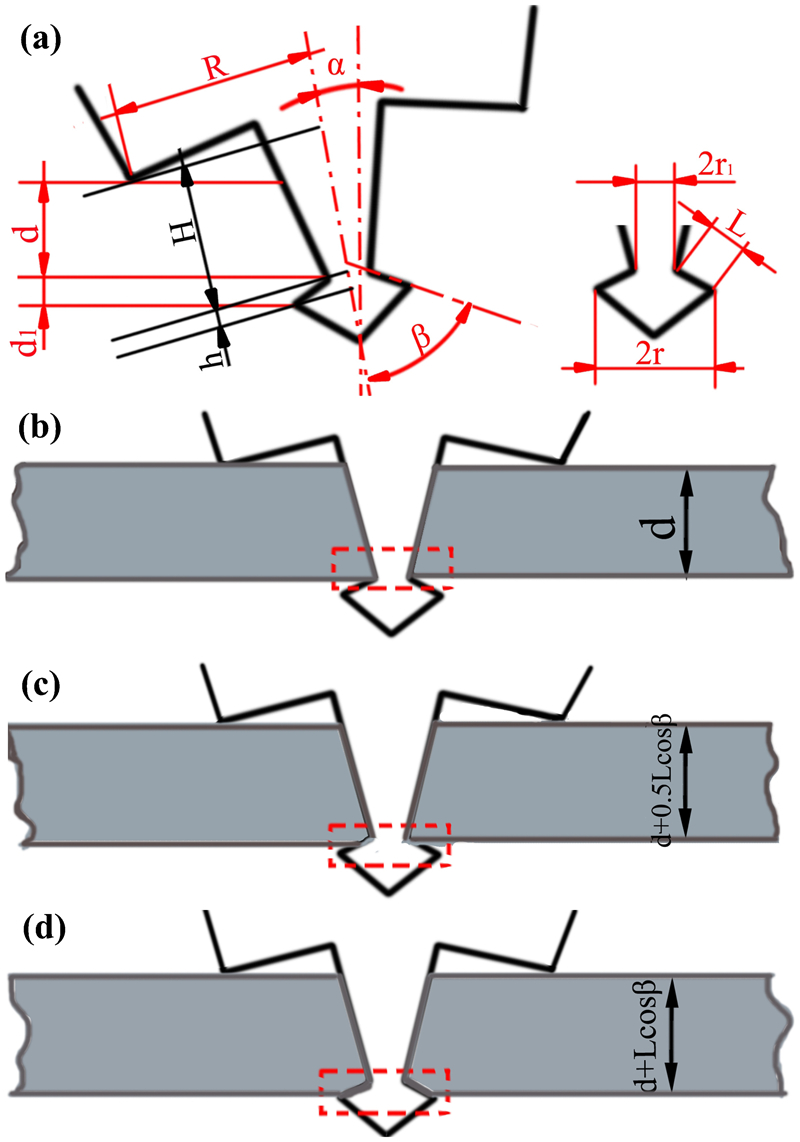
a some important parameters related to adjustability of thickness of plates when α = 0°, b minimum thickness of plate, c thickness of plate changing from d to d+0·5Lcos β and d maximum thickness of plate
From equations (3) and (6), we can see that the variation of tool tilt angle α is related to the thickness of the plate that the SSFSW tool can adapt to. When other parameters are fixed, the range of thickness of the plate is reduced with the increase in α. Figure 3 shows the upper and lower surfaces of weld seam with different kinds of tilt angles with a rotation rate of 800 rev min−1, a welding speed of 100 mm min−1 and a rolling depth of 0·1 mm. When α values are 1·5 and 2°, large weld flashes appear on both upper and lower surfaces. When α is 1·5°, a long groove can be seen along the weld seam. However, weld flashes are relatively less with the increase in α, especially when α is 3°; there is almost no weld flashes on both surfaces. It can be attributed to the variation of tool tilt angle α. As the α increases, both the upper shoulder and lower shoulder can contact with the plate more fully, resulting in the reduction in weld flashes.
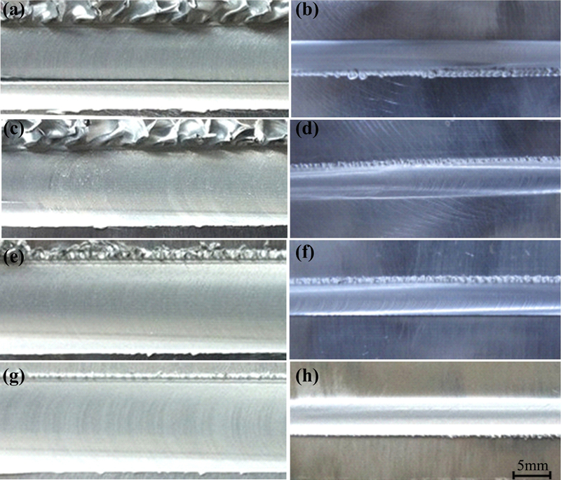
Comparison of upper and lower surfaces of SSFSW weld seam with different kinds of tilt angles
Figure 4b and c shows that the root flaws have been eliminated because the lower shoulder penetration and uniform ripples have been got both on the upper and lower surfaces. The shoulder region of tool provides an additional friction treatment to the workpiece surface and prevents plasticised joint material from being expelled.9 Two shoulders provide sufficient heat generation from both sides of the workpiece. Containment of reactive forces within the tool itself means that compressive deformation of the probe does not occur. The actual surfaces of upper and lower welding seam of SSFSW compared with that of conventional FSW seam are shown in Fig. 4. The diameter of upper and lower welding seam is similar to that of upper and lower shoulder respectively. The ripples of lower surface of conventional FSW seam did not exist due to the lack of tool penetration.
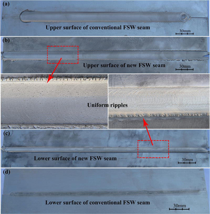
a upper surface of conventional FSW seam, b upper surface of SSFSW seam, c lower surface of SSFSW seam and d lower surface of conventional FSW seam
Tensile properties of new FSW joints
Tensile test results indicate that the average tensile strength and elongation of 6005A aluminium alloy joint with a thickness of 5 mm is 190 MPa and 6·86% respectively. The fracture surfaces of tensile specimens are characterised using SEM to understand the failure patterns. Figure 5 shows that both the fracture surfaces of the samples after conventional FSW and SSFSW consist of fine dimples, indicating that the samples fail in ductile manner upon tensile loading. This feature validates the high ductility of SSFSW joint during tensile testing.
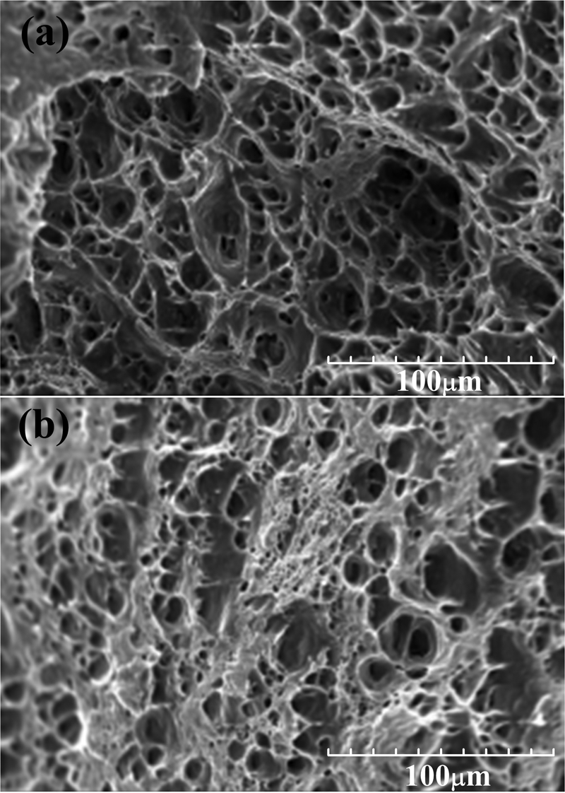
Tensile fractured morphologies of conventional FSW and SSFSW joints
The tensile properties and fracture locations of the joints are dependent on the microhardness distributions and the weld defects of the joints.15, 16 Figure 6 shows the variations of microhardness of joint cross-section. As seen, the microhardness falls dramatically in the region that is passed over by the shoulder and the microhardness reaches its lowest value in the softening region. The minimum hardness is located at the interface between the thermomechanically affected zone (TMAZ) and the heat affected zone (HAZ).
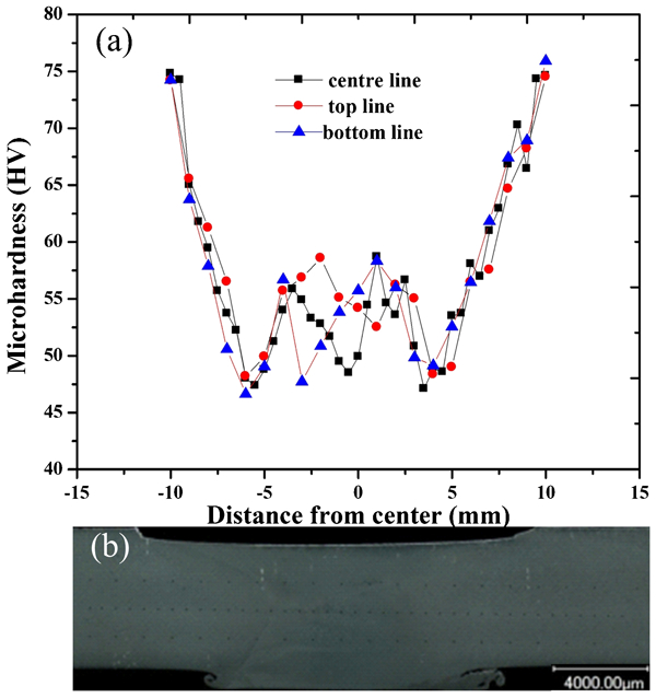
Microhardness of joint in different regions taken from top, middle and bottom along thickness direction
Macro- and microstructures of joints
Typical macrosections are shown in Fig. 7. The weld shape differs from the weld made from conventional FSW, which is slightly hourglass shaped. Single onion ring pattern observed in the welding nugget in the conventional FSW welds is replaced by series of onion rings stacked vertically through the thickness in the probe dominated midsection.13 There does not macroscopically exist root flows in the joint. However, a layer resulting from the outflow of plastic material is formed at the lower surface. Based on microstructural characterisation shown in Fig. 8, three distinct zones, i.e. HAZ, TMAZ and weld nugget zone (WNZ), have been identified in the joint. The WNZ consists of two parts, the upper WNZ and the lower WNZ, as shown in Fig. 7b. The WNZ is directly influenced by the tool pin. The nugget is the central weld region where the tool piece pin passes through the material. It is subjected to a high level of plastic deformation and frictional heating. The nugget size is typically slightly greater than the pin diameter. The grains are refined in WNZ. This refinement is the result of dynamic recrystallisation and combines action of high rate strain and elevated temperatures.17– 19 The TMAZ is the region beside the nugget. The TMAZ experiences both temperature and deformation during SSFSW and is characterised by a highly deformed structure. The transition appears sharp on the advancing side of the weld, particularly at the bottom of the weld, while it is more gradual and wide on the retreating side. An abrupt change in structure is observed at the edge of TMAZ defined as the TMAZ/HAZ boundary, separating the comparatively large grains from the fine grains associated with HAZ. The TMAZ/HAZ boundary in the lower part is more obvious compared with the conventional FSW joint, as shown in Fig. 8c and f. The HAZ experiences a thermal cycle, but does not undergo any plastic deformation. The HAZ retains the same grain structure with the parent material.
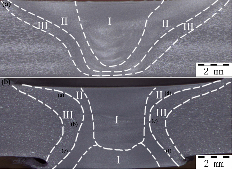
Three distinct zones (I: WNZ; II: TMAZ; III: HAZ)
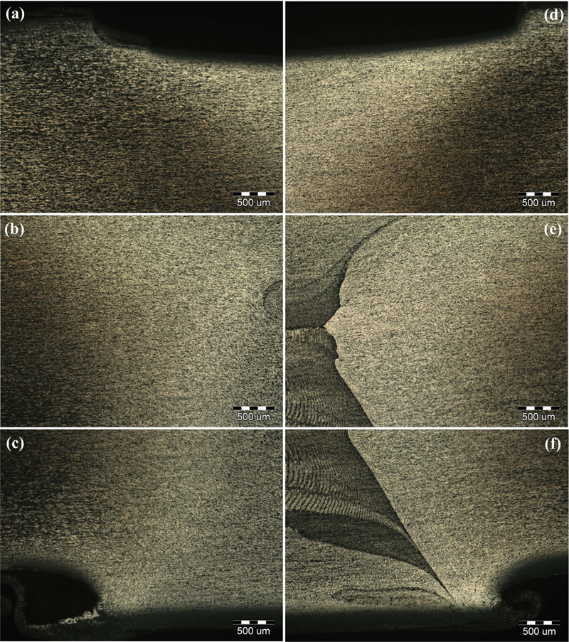
Photo of microstructure of joint in different regions taken from top, middle and bottom along thickness direction of Fig. 7b
Conclusions
This study presents a new technique of SSFSW with adjustable dip angle to join hollow extrusion. Some experiments are carried out on 6005A aluminium alloy to investigate the efficacy. This SSFSW process can realise the self-support and no any backing bar is required for the joint of aluminium hollow extrusion. Compared with the conventional FSW, root flaws due to the lack of tool penetration have been eliminated. Compared with BTFSW tool, SSFSW tool does not need predrilled pilot holes so that the welding process can be simplified. The SSFSW tool can realise the adjustability of the thickness of the plate due to a convex lower shoulder. The average tensile strength and elongation of 6005A aluminium alloy joint is 190 MPa and 6·86% respectively. Furthermore, the failure of specimen presents a ductile fracture in the typical joint. These results suggest that SSFSW has potential for practical application in industry for welding aluminium hollow extrusion.
Footnotes
Acknowledgements
The work was jointly supported by the National Natural Science Foundation of China (grant no. 50904020) and the Fundamental Research Funds for the Central Universities (grant no. HIT. NSRIF. 2012007).