
Abstract
This study, which pertains to the butt welding of 590 MPa high strength steel plates with a high power laser over gaps, was conducted to investigate weld penetration characteristics, to clarify welding phenomena, and to develop procedures for obtaining high quality joints. Butt welding was performed on 12 mm thick plates with a 16 kW high power disc laser together with a hot wire. In this way, welding defects are suppressed and weld metal oxygen content is controlled, thereby producing sound, fully penetrated welds. Penetrations were stable over a range of gaps from 0 to 0·4 mm, owing to an ejection of excess melt through a keyhole outlet at the bottom of the molten weld pool by a strong plume. Here, the use of a hot wire together with a laser of sufficient power to produce a fully penetrated keyhole was effective in improving the gap tolerance and suppressing oxygen inclusion within the butt weld.
Introduction
Owing to superior strength and toughness, high strength steel is widely utilised in automobiles, ships and bridges to reduce weight and enhance safety.1– 3 There is thus much interest in methods of producing high quality welded joints between high strength steel plates without any need for pre- or post-heating.
High power lasers, including fibre and disc lasers, hold much promise as heat sources for the formation of deep penetration welds. Yet, while they do offer a high power density, the tight focus of their beam spots translates into a low degree of gap tolerance in butt welding. In this regard, some researchers have explored hybrid laser/arc welding methods that are intended to raise the degree of gap tolerance.4– 8 When welding high strength steel, care must be taken to avoid excess heat input, which may act to soften the heat affected zone or increase the oxygen content of the weld metal. To optimise heat input under laser welding, several fundamental studies have explored the use of a ‘hot wire’, which is a filler wire heated by Joule heating.9– 11 Yet, even with these efforts, much remains to be understood with regard to butt welding behaviour and properties under a high power laser/hot wire combination.
In this study, we laser butt welded 590 MPa high strength steel plates of 12 mm thickness while using either a cold wire or a hot wire. The gaps between the plates to be joined were of the same approximate size as the laser spot diameters of the apparatus used (either a 10 kW fibre laser or a 16 kW disc laser). The objectives of this research were to investigate weld penetration and welding defects, to elucidate related phenomena, and to obtain fundamental knowledge for use in raising gap tolerance and controlling weld metal oxygen content.
Materials and methods
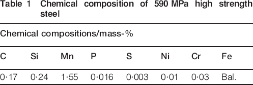
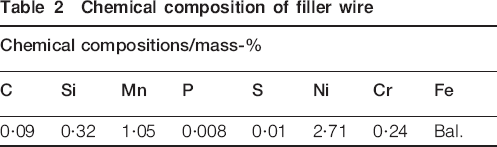
The materials used in this study were 12 mm thick high strength (590 MPa) steel plates and low carbon (high toughness) steel filler wire with a diameter r of 12 mm. Tables 1 and 2 show the chemical composition of the steel plates and wire respectively. Figure 1 shows a schematic diagram of the experimental apparatus. The laser device was either a fibre laser (wavelength λ: 1070 nm; beam parameter product: 10·8 mm mrad; max power: 10 kW) or a disc laser (λ: 1030 nm; beam parameter product: 8 mm mrad; max power: of 16 kW). The laser beam was transmitted through an optical fibre and focused onto the central part of the gap by a lens having a focal distance of 250 mm. The laser irradiation angle was set perpendicular to the steel surface. Maximum plate/plate gap width g was of the same approximate size as the laser spot at the focus position (φ300 μm for the disc laser and φ460 μm for the fibre laser). The filler wire was fed in front of the molten weld pool at an angle α of 55° from the optical axis of the laser beam. Wire was fed at a feed speed vw, calculated with the following equation such that the volume of the wire supplied corresponded to the volume of the gap to be filled

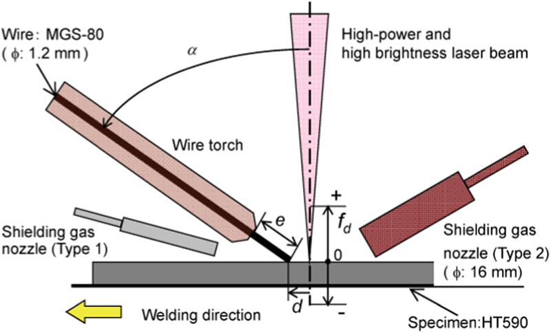
Schematic of experimental set-up for laser butt welding of thick, high strength steel plate with hot and cold wire
Chemical composition of 590 MPa high strength steel
Chemical composition of filler wire
In this experiment, the filler wire was made into a hot wire by Joule heating. The power supply for this heating drew a maximum current of 160 A. An elongated shielding gas nozzle (Type 1 nozzle) with 14 holes of 1 mm in diameter was inclined at an angle of 15° to the horizontal axis. The nozzle supplied argon at a flow of 666 666 mm3 s−1, a rate selected to avoid obstructing the melt flow within the molten pool. In some cases, a pipe shaped nozzle (Type 2 nozzle) was used having an inside diameter of 16 mm and set an angle of 45° from the horizontal axis. This nozzle was used to supply shielding gas from the rear of the laser irradiated spot in order to control the oxygen content of the weld metal. Argon, helium or carbon dioxide was used as the shielding gas. Bottom shielding was not used in this series of experiments. To measure the oxygen content of the weld metal, sample slices were cut from the central part of the weld zone with an electric discharge machine to dimensions 12×1×6 mmt. Three such samples were prepared for precise measurement with an oxygen–nitrogen analyser. The measured values were averaged, with the average taken as the experimental value.
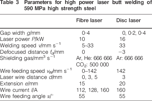
Table 3 presents experimental conditions for this research. Here, defocused distance fd is taken to have its origin at the steel surface, such that when the focus is above the surface, defocused distance fd is positive and, when below the surface, negative. To clarify characteristic welding phenomena, the behaviour of the molten pool and filler wire was photographed with a high-speed (frame rate: 5000 frames s−1) video camera. To block the glare of the laser induced plume, we utilised an interference filter matched to the wavelength emitted by the 30 W laser illumination sources (λ: 980 nm).
Parameters for high power laser butt welding of 590 MPa high strength steel
Results and discussion
Butt welding of thick, high strength steel plate with high power laser and hot wire
High strength steel plates were arranged so that the focal position fell on the top plane of a 0·4 mm gap between the plates. Then, with a 10 kW fibre laser and at a 17 mm s−1 welding speed, the plates were butt welded, sometimes with only the laser, sometimes with the laser and a cold wire, and sometimes with the laser and a hot wire. Experimental results are shown in Fig. 2. In these experiments, laser wire distance d was 1 mm for the cold wire and 3 mm for the hot wire. The wire feed speed νw was 72 mm s−1 for both. Wire current I was 160 A for the hot wire and 0 A for the cold wire.
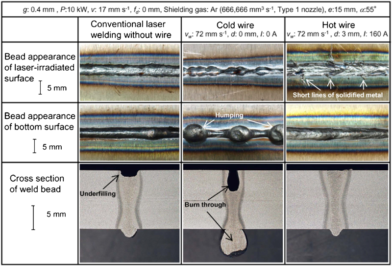
Typical bead appearances and cross-sections of full penetration joints (10 kW fibre laser, 17 mm s−1 welding speed) without wire, with cold wire and with hot wire
In conventional laser welding without a filler wire (Fig. 2, left), an underfill of about 2 mm in depth was formed along the laser irradiated (top) surface of the obtained bead. In welding with a cold wire (Fig. 2, centre), weld metal, while filling the gap, burned through the bottom surface at multiple points. Also, humping (beads) occurred along the bottom surface. In welding with a hot wire (Fig. 2, right), on the other hand, the welded bead exhibited short lines of solidified metal extending perpendicular to the weld direction along the laser irradiated surface, with no burn-through or humping and greatly improved weld penetration. Underfill, at less than 0·2 mm, was markedly restrained in comparison with the case in which only a laser (no wire) was used.
To more fully investigate the difference in results when welding with a cold wire and when welding with a hot wire, we carried out experiments at welding speeds ν ranging from 5 to 33 mm s−1. Figure 3 shows the penetration depths obtained as function of welding speed v. When using a cold wire (Fig. 3a), full weld penetration was obtained at all v less than 20 mm s−1; however, burn-through also occurred at each v up to that speed. When using a hot wire (Fig. 3b), full penetration was obtained up to a welding speed v of 27 mm s−1. Moreover, underfilling was reduced to approximately 0·2 mm over the range of v from 13 to 25 mm s−1. Here, we note that laser welding with a hot wire can produce full penetration butt welds over a 0·4 mm gap while suppressing both burn-through and underfilling.
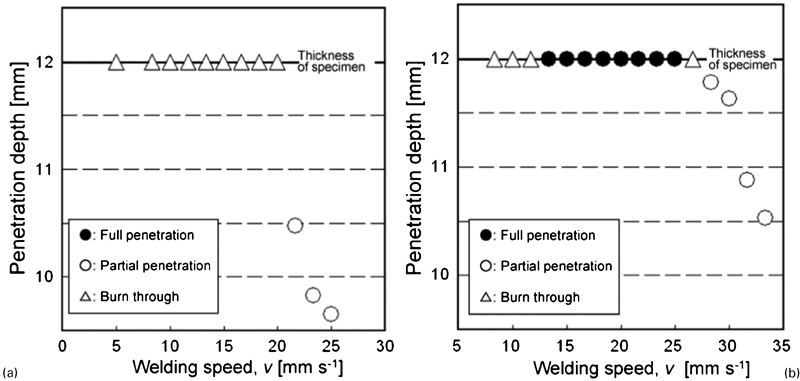
Effects of welding speed on weld penetration (10 kW fibre laser) with a cold wire or b hot wire
Influence of hot wire on welding results
Our next experiment considers the effects of laser wire distance d and wire current I on butt welding. The welding conditions when using a hot wire are the same as those shown in Fig. 2 (right). Laser wire distance d was varied to 0, 3 and 5 mm. Figure 4 shows typical bead surface appearance together with high speed video frames of the wire and molten pool. At a distance d of 0 mm, the tip of the wire was irradiated directly by the incident laser beam; accordingly, the bead surface was rough with much spattering. High speed camera observation reveals that (1) the molten wire formed spatters at irregular intervals and (2) the molten pool was partially convex. That is, the welding process was not stable. At d = 3 mm, the bead has a good appearance. High speed camera observations indicate that the wire was grounded right in front of the molten pool, whereupon it softened into a large lump and slid into the molten pool. This enabled stable energising and wire feeding. And, at d = 5 mm, the obtained weld bead shows some linear molten metals. It was observed here that the lump formed by the wire was wider than the molten pool, such that a portion of the softened wire was ejected linearly.
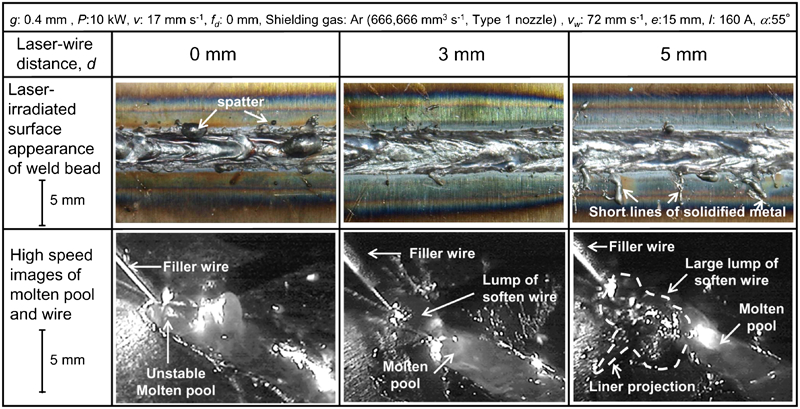
Weld bead appearances and high speed photographs of molten pools and hot wire feeding at several laser wire distances
The next experiment considered wire current I, an important parameter for determining the degree of hot wire heating. Wire currents I supplied to filler wire were 112 A (at which Tjoule, the temperature at the tip of the hot wire as calculated in a report12 under a consideration of Joule heating, comes out to 404 K), 128 A (Tjoule: 443 K) and 160 A (Tjoule: 545 K). Figure 5 shows the surface appearances of the obtained beads, cross-sections of the welds, and high speed video images of the molten pool and hot wire. When I was 112 A, the tip of the wire glided along the steel surface and slipped directly into the molten pool without melting; thus, burn-through occurred. When I was 128 A, only the tip of the wire softened and was deposited on the surface as a lump. The tip of the wire was stably fed just ahead of the molten pool without gliding along the surface. When I was 160 A, the wire overheated. Its tip irregularly fused and broke, frequently spattering molten wire along the surface.
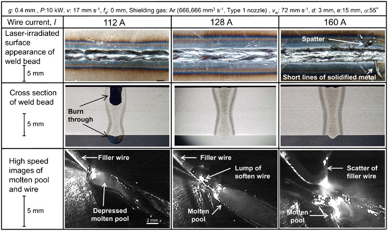
Weld bead appearances, cross-sections of weld beads, and high speed photographs of molten pools and hot wire feeding at several wire currents
Effects of hot wire laser welding on weld metal oxygen content
The inclusion of oxygen in a martensitic structure within the weld fusion zone of an ultrahigh strength steel can have an adverse effect on toughness and other mechanical properties. Accordingly, in order to maintain the material properties of a martensitic steel, it is important to suppress its oxygen content to the greatest extent possible. Here we conducted several experiments to investigate ways to control (suppress) oxygen inclusion within weld metal, techniques which may someday prove beneficial for the welding of martensitic ultrahigh strength steel.
In one experiment, a weld was formed while blowing argon through a Type 1 nozzle (this type of nozzle maintains a blanket of shielding gas over the molten pool without obstructing melt flow behind the keyhole), as used in the experiments of the sections on ‘Butt welding of thick, high strength steel plate with high power laser and hot wire’ and ‘Influence of hot wire on welding results’. The oxygen content of the weld metal thus obtained was 150 ppm, which is much higher than 11 ppm oxygen content of the base material. Next, we formed full penetration welds while using a Type 2 nozzle to cover the entire molten pool with a shielding gas of helium, argon or carbon dioxide. Figure 6 shows the oxygen content of the weld metal and the cross-section of the weld thus obtained under each shielding gas. The oxygen contents of the joints welded under carbon dioxide, argon and helium were considerably better (lower), at 29, 43 and 98 ppm respectively. The oxygen seems to be supplied by decomposition of CO2 gas in the laser welding. On the other hand, argon and helium are inert gases and helium is superior to argon in cooling action at the weld. Therefore, the oxygen amount was considered to be reduced. However, remarkable burn-though occurred at some points when using helium or argon, which kept the oxygen content below 50 ppm. We infer that this phenomenon occurs because the gradient of the surface tension changed with amount of the oxygen content, which was reported in the paper.13
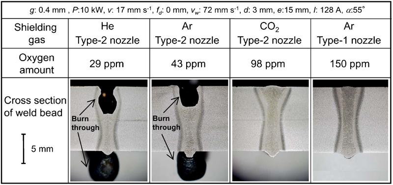
Cross-sections of weld beads, oxygen content in weld fusion zone under several shielding conditions
High speed video images of the molten pool were examined to elucidate burn-though behaviour at low oxygen content. Figure 7 shows results for argon gas shielding as applied through a Type 1 nozzle (Fig. 7a) and a Type 2 nozzle (Fig. 7b). With the Type 1 nozzle, a laser induced plume was observed on both top and bottom surfaces. In addition, few spatters were observed, and the behaviour of the molten pool on the laser irradiated surface was stable. On the other hand, with the Type 2 nozzle, a laser induced plume occurred on only the laser irradiated surface. This suggests that the keyhole did not fully penetrate the molten pool. Furthermore, the molten pool on the laser irradiated surface sank immediately behind the keyhole; and along the bottom surface, a convex portion formed behind the keyhole, with that portion subsequently built up by melt flowing from the rear of the keyhole. Then, solidification would occur at a narrow point ahead of the molten pool, the convex portion would be deposited and a humping bead would form. We infer that the periodic spacing of the humping beads on the bottom surface is attributable to repetition of this sequence.
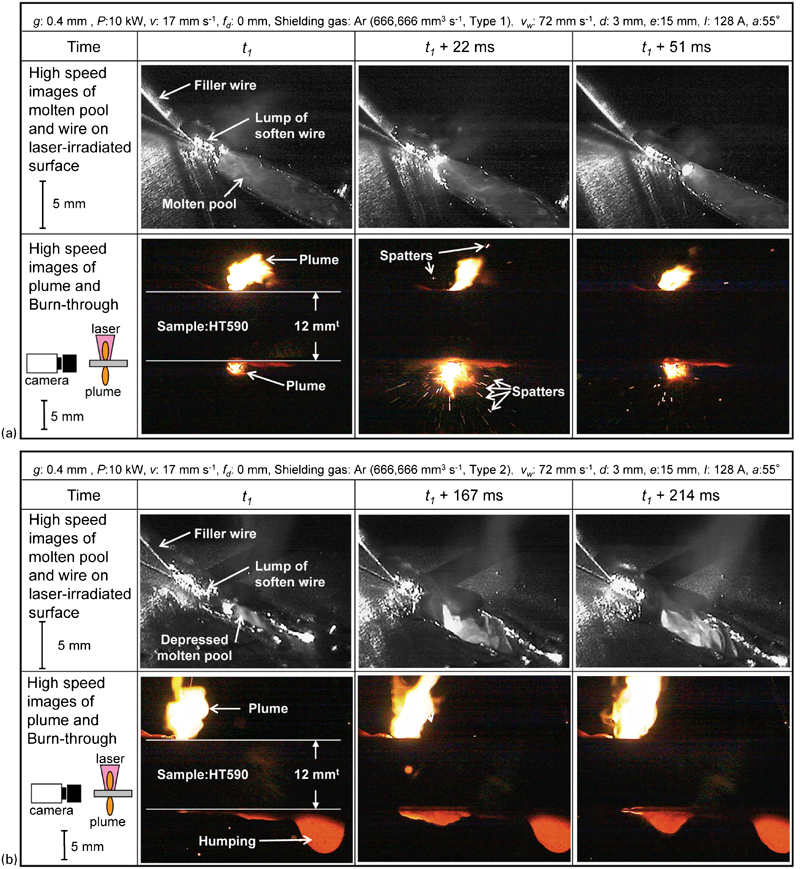
a Type 1 gas nozzle; b Type 2 gas nozzle
Figure 8 shows a schematic diagram of a suggested mechanism for burn-through within a steel by a low oxygen content weld metal. Under a low oxygen content, as the temperature of the molten pool decreases, its surface tension increases. Furthermore, under the welding conditions examined here, the keyhole does not always penetrate fully through the molten pool. When the keyhole is not fully penetrated, there will be a downward melt flow at the keyhole tip. That melt will be pulled to towards the rear of the keyhole by surface tension because the temperature there is lower. As a result, a convex portion will form on the bottom surface, the molten pool on the laser irradiated surface will become concave, burn-through will occur and a humping bead will be deposited.
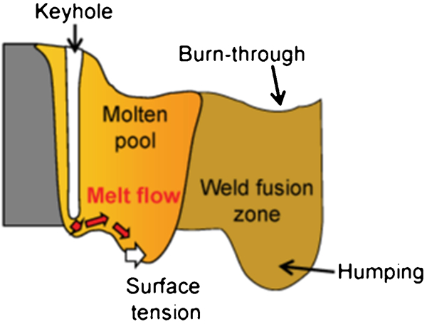
Schematic illustration of burn-through hump formation
Full penetration welding with hot wiring and oxygen content control
Above, we saw that when welding was carried out under an argon shield supplied through a Type 2 nozzle, the oxygen content in the weld metal could be suppressed to around 50 ppm, but burn-through would occur. In addition, the lack of a constant plume at the bottom surface suggests that the keyhole did not fully penetrate the molten pool. Here, we examine the possibility that the use of a laser beam with more than 10 kW in power may enable high speed operation with full molten pool penetration, thereby producing a low oxygen content joint and improving burn-through characteristics. In our next experiment, we investigate whether better welding results can be obtained by increasing the laser power to 16 kW.
We used a 16 kW disc laser, argon shielding through a Type 2 nozzle, and hot wiring. For this experiment, we set gap width g to 0·4 mm, and welding speed ν, wire feed speed νw and wire current I to 33 mm s−1, 142 mm s−1 and 160 A respectively. In consideration of the extreme increase in power density with the increase in laser power from 10 to 16 kW, we set defocused distance fd to −3 mm. Figure 9 shows the appearance of the weld bead thus obtained. No porosity was observed within any section and good penetration was achieved free of welding defects. The oxygen content of the weld fusion zone was 31 ppm, substantially lower than that obtained under a laser power of 10 kW. The hardness of the weld fusion zone was 397 HV, somewhat harder than the base steel at 205 HV.

Typical bead appearance and cross-section of full penetration joint produced using hot wire and 16 kW disc laser
In practical industrial situations, gap width is often not constant. Our next experiment examined gap tolerance by providing a constant wire feed for butt joints across different gap widths. Using a 16 kW laser, we formed butt joints over two gap widths, 0 and 0·2 mm. Figure 10 shows the appearances of the beads and weld cross-sections; also presented for reference are similar photographs taken upon butt welding over a gap of 0·4 mm. As for weld penetrations when butt welding across gap widths of g = 0 and 0·2 mm (in which excess hot wire was supplied), the bead surface is more greatly swelled compared with that across a gap width of g = 0·4 mm. No notable burn-through induced humping occurred with a gap width g of 0 or 0·2 mm. In addition, although the height of the weld bead along the bottom surface was approximately 1 mm at the maximum, there was no appreciable difference between that obtained across the range of gap widths from 0 to 0·4 mm.
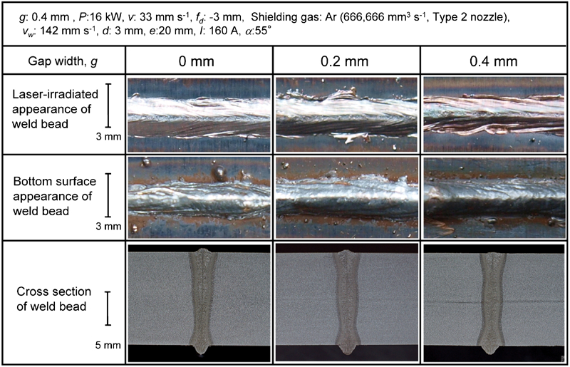
Typical bead appearances and cross-sections of full penetration joints produced by laser butt welding over gaps from 0 to 0·4 mm
For each gap width g, keyhole inlet and molten pool behaviour were observed using a high speed camera. The results are shown in Fig. 11. When g was 0·4 mm, many minor spatters were ejected from keyhole inlet on the bottom surface during welding. When g was 0·2 mm, small spatters were ejected from the keyhole. When g was 0 mm, the size and the number of the spatters ejected from the keyhole increased. When excess hot wire is fed to the molten pool, penetration shape may be maintained without any manual intervention by blowing the extra melt out through the keyhole on the bottom surface. Note that with this approach, post-processing (spatter removal) is necessary.
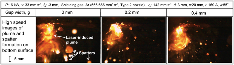
High speed video images of laser induced plumes and spatters generated on bottom surface under several gap widths
The reason why good penetration was produced by 16 kW laser power is conceptually illustrated in Fig. 12. In high power welding, the keyhole fully penetrates the molten pool, and downward melt flow from the keyhole is small. Because extra melt is ejected as spatter, no burn-through (or humping) occurs along the bottom, even at low weld metal oxygen contents.
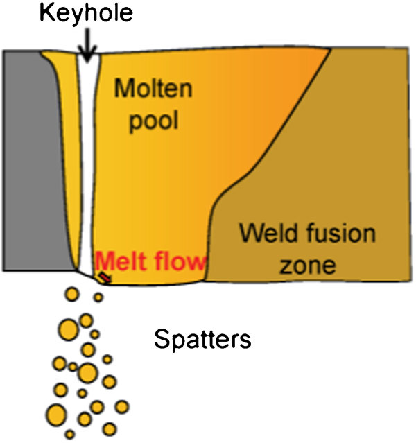
Schematic illustration of burn-through suppression
These results show that the use of a hot wire together with a laser having enough power to maintain a keyhole that fully penetrates the weld pool offers an effective means of producing fully penetrated weld joints without defects and with good control over weld metal oxygen content. Furthermore, with regard to gap tolerance (i.e. the feeding of hot wire at a uniform rate irrespective of gap size), penetration shape can be maintained without the need for manual intervention by if excess melt is ejected out the bottom through the keyhole.
Conclusions
In this study, a high power laser and filler wire were used to butt weld high strength 590 MPa grade steel plate across a plate/plate gap of the same approximate size as the laser spot diameter. Phenomena pertaining to weld penetration and welding defects were clarified, and a method of producing high quality defect free welds free was developed and applied, whereupon the following results were obtained:
In butt laser welding across a gap, a fully penetrated (low underfill, no burn-through) welded joint can be produced by using a hot wire.
Under our experimental conditions, we found that optimum values exist for hot wire position and wire current; that the laser beam does not directly irradiate the wire, but rather only softens the tip of the wire so it is deposited on the steel surface as a lump; that the tip of the wire remains stable such that it would be fed just before the molten pool without gliding along the plate surface; and that full penetration provides a means to control burn-through and spattering.
When welding with a 10 kW fibre laser, an oxygen content in excess of 100 ppm promoted full penetration and suppressed underfilling, while an oxygen content of less than 50 ppm led to burn-through.
A 16 kW high power disc laser with a hot wire is capable of producing sound, fully penetrated welds with few welding defects and a low oxygen content in the weld fusion zone. Weld penetrations were stable over differing gaps from zero to 0·4 mm, owing to removal of excess melt from the bottom keyhole by a strong laser induced plume.
In the butt welding of thick high strength steel plates with a high power laser, the use of a hot wire together with a laser with sufficient power to produce a fully penetrated keyhole was effective in improving gap tolerance and suppressing oxygen content in the weld fusion zone.
Footnotes
Acknowledgements
A portion of this study was carried out under a New Energy and Industrial Technology Development Organization project on the research and development of innovative, high strength/high function steel materials.