
Abstract
In this work, a new heating tool friction stir spot welding (HT-FSSW) process was developed, and its impacts on the microstructure and mechanical properties of the welded AZ31 magnesium alloy joints were investigated by microstructure observation, tensile tests and microhardness tests. An increase in the heating tool temperature resulted in a decrease in the grain size of the stir zone (SZ) and an increase in the grain size of the thermomechanically affected zone (TMAZ). The rising heating tool temperature also aggrandised the bonded zone width and enhanced the tensile shear load strength per unit area of the HT-FSSW welded joints. With an increase in the heating tool temperature, the microhardness of SZ increased while that of the TMAZ decreased. Moreover, the slope of the Hall–Petch relationship between microhardness and grain size of the TMAZ is larger than that of the SZ.
Introduction
Magnesium alloys have many attractive advantages.1, 2 Therefore, they are considered as promising replacements of aluminium alloy and carbon steel structure parts to achieve the goal of weight reduction in the automotive industry. Thus, the jointing of magnesium alloy becomes critical in complicated structure parts under the current state. At present, jointing of the body plates is mainly obtained by resistance spot welding technique in the automotive industry. However, because of the strong cracking susceptibility of resistance spot welded magnesium alloy joints, 3 the serious corrosion of magnesium to electrode 4 and the high energy requirement, 5 resistance spot welding technique is not a good choice for welding magnesium alloys.
Friction stir spot welding (FSSW)6–8 is a derivative of friction stir welding9, 10 technology developed by TWI, UK, which is a solid state welding process with energy and equipment saving advantages and no consideration taken into the incompatibility of dissimilar materials. Compared with the traditional resistance spot welding technique, the gas tungsten arc welding process and the laser welding process for magnesium alloy, a superior attribute of the FSSW is that no fusion of the base material (BM) appears during welding, which avoids a large number of welded defects (such as pores and cracks) formed in the joints. Hence, this welding technology is a perfect fit for joining non-ferrous metal, especially magnesium alloys. 11 However, since the FSSW welded joint is achieved by severe plastic deformation, the deformation ability of magnesium alloys is poor due to the hexagonal close packed structure of magnesium at relatively low temperature, which leads to a reduction in the mechanical properties of the FSSW welded magnesium alloy joints. 5 Moreover, in contrast to the friction stir welding process, FSSW is believed as a transient process because of its short cycle time. 12 The high heating and cooling rates of the material induce short heating time and low heat input. Therefore, more voids, narrower contact zone and wider partial metallurgical zone appear in the joint.13–15 Although increasing the rotational speed and the downward force may increase the heat input, it as well increases the residual stress of the weldment. 16 Recently, Shen and Min 17 had developed a heating FSSW technology for magnesium alloy sheets to achieve a high quality welded joint by heating the magnesium alloy sheet and improving the deformation ability of the magnesium alloy. However, because of the good thermal conductivity of the magnesium alloy, much energy is required to heat the workpiece to the predetermined temperature with undesirable coarsening of the BM grains. Moreover, this process of low efficiency is inconvenient and unavailable for large structure parts, and more sophisticated heating equipments are needed.
In this paper, another heating FSSW technique [heating tool FSSW (HT-FSSW)] was designed to improve the microstructure and mechanical properties of the FSSW welded AZ31 magnesium alloy joint. The effects of heating on the microstructures, tensile property and microhardness of the HT-FSSW welded joints were examined. Moreover, the relationship between the microstructure and the mechanical properties of the welded joints were discussed in detail.
Experimental
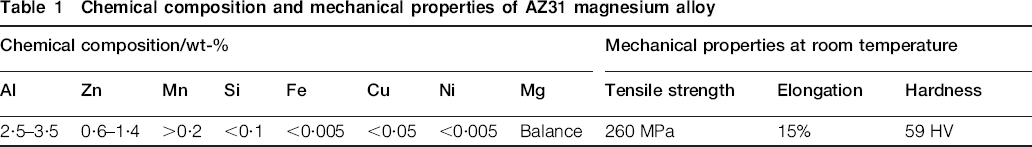
Commercially available hot extruded AZ31 magnesium alloy plates in the annealed state with a size of 100×22×2 mm were chosen for the tests. Its chemical compositions and mechanical properties are listed in Table 1. All the specimens were welded in lap configuration with a 25×22 mm overlap area, as shown in Fig. 1. The FSSW was applied in the centre of the overlap area. Before welding, the surfaces of all the specimens were polished slightly using diamond powders, and then they were cleaned with acetone in order to avoid the influences of impurities on the results of the welding test. Both FSSW and HT-FSSW welding were performed under the same processing condition (1400 rev min−1 tool rotational speed and 2·8 mm pin plunge depth) with an H13 tool in a flat shoulder diameter of 12 mm, a pin diameter of 4 mm and a pin length of 2·5 mm. The HT-FSSW welding tests were carried out by heating the rotating tool with nature gas (as shown in Fig. 2) before welding. The temperatures of the tool were heated to 373, 473, 573, 673 and 723 K respectively. The temperature was measured by an infrared thermometer. Once the tool was heated to the predetermined temperature, the FSSW process was performed immediately. During both FSSW and HT-FSSW welding tests, a thermocouple was inserted in the nugget to test the peak temperature T the stir zone (SZ) experienced when plunging the tool, and the plunging time t for the tool plunged into the specimens was recorded.

Schematic illustration of lap configuration (mm) and tensile test configuration (mm)
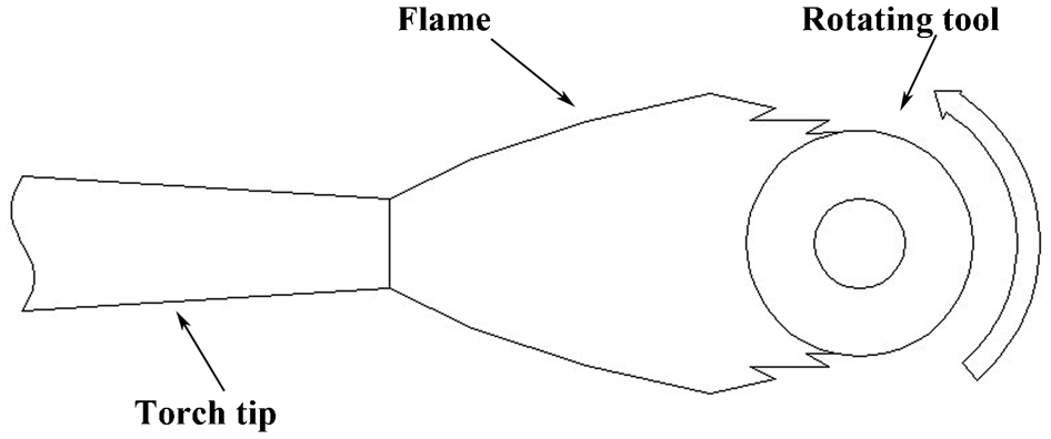
Schematic illustration of heating rotating tool
Chemical composition and mechanical properties of AZ31 magnesium alloy
After the welding tests, specimens with a length of 22 mm and a width of 10 mm for metallographic study were cross-sectioned through the centreline of the spot welds by a numerically controlled linear cutting machine. Then, these specimens were prepared using a standard metallographic procedure. 2 The lap shear tensile tests (as shown in Fig. 1) went on at room temperature using a tensile machine (SANA-XUA305C) with a tensile speed of 0·5 mm min−1. The microhardness tests were operated using a Vickers hardness tester (V-1000) with a period of 20 s, a load of 100 g and a step size of 0·25 mm. Five welded specimens under the same welding condition were used for the above tests, and the mean values of them were adopted. The microstructure was examined by optical microscopy and SEM (VEGA3 TECSAN).
Results and discussion
Microstructures
Traditional FSSW welded AZ31 magnesium alloy joint
Figure 3 shows the FSSW welded AZ31 magnesium alloy joint. From Fig. 3a, it can be seen that the joint was not bonded well. Figure 3b shows the typical microstructural distribution of the FSSW welded AZ31 magnesium alloy joint. Based on microstructural characterisation of grains, three distinct zones [SZ, thermomechanically affected zone (TMAZ) and heat affected zone (HAZ)] were formed in sequence from the periphery of the weld keyhole towards the BM. It can be seen that the SZ and bonded zone (mainly composed of SZ) are narrow (the width of the bonded zone is ∼150 µm). Voids of different sizes and cracks are discovered in TMAZ and other regions of the FSSW welded AZ31 magnesium alloy joint, but none is found in SZ, as shown in Fig. 3a and b. These defects distribute far away from the metallurgical part and are mainly in the upper sheet. This is because the higher temperature in SZ improved its material deformability and fluidity, whereas the deformability of other regions under the lower temperature is poor. Therefore, when the tool shoulder exerted downwards force on the upper sheet, intense plastic deformation produced voids and cracks in the joints, but the material flow in SZ filled these defects and eliminated them. From Fig. 3b, it can be seen that the hook geometry reaches the SZ in a slanting direction. The interface slope β, 18 describing the angle between the initial interface and the post-welded curving interface, indicates the resistance to deformation of materials during the FSSW welding process. The smaller the interface slope β, the smaller the deformation resistance of the material. The value of the interface slope β of the FSSW welded joint is ∼139°, which implies that the deformation resistance of AZ31 magnesium alloy during FSSW was relatively high. Figure 3c shows the partial metallurgical joint, which features the discontinuous oxide particles. 19
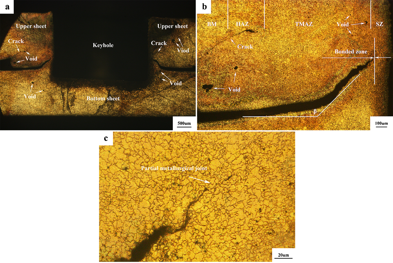
a low magnification image of FSSW welded joint; b microstructure distribution; c partial metallurgical joint
Figure 4 shows the microstructures for different regions of the FSSW welded AZ31 magnesium alloy joint. The BM is composed of a uniform equiaxed structure, as shown in Fig. 4a. Owing to the dynamic recrystallisation resulting from the severe plastic deformation of the material, the SZ is characterised by dispersed tiny grains, as shown in Fig. 4b. In Fig. 4c, it can be seen that the TMAZ is a transition zone between the BM and the SZ. The grains of the TMAZ are relatively fine but coarser than those of the SZ. This is because the TMAZ experienced both temperature and deformation during the FSSW welding process. Next to the TMAZ, there exists a HAZ. Because this zone only experienced a thermal cycle and did not undergo any dynamic recrystallisation, its grains are distinctly coarse, as shown in Fig. 4d.
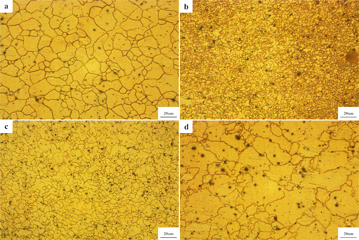
a BM; b SZ; c TMAZ; d HAZ
Heating tool friction stir spot welded AZ31 magnesium alloy joints
Figure 5 shows the microstructure of the HT-FSSW welded AZ31 magnesium alloy joint at 723 K (as a representative for other HT-FSSW welded specimens). Figure 5a displays a perfect joint. From Fig. 5b, it can be seen that the bonded zone width of the HT-FSSW welded joint is ∼1100 µm, far larger than that of the FSSW welded joint. In addition, none of the voids or cracks was founded in the joint. Because of the HCP crystal structure of magnesium with less operative slippage systems at low temperature, the plastic deformation of magnesium alloy mainly lies on the activity of the hard non-basal slippage system, which is determined by the critical resolved shear stress (CRSS). 20 The CRSS depends on the temperature of the magnesium alloy. The report by Ono et al. 21 on the deformation mechanism of polycrystalline magnesium pointed out that the CRSS of the non-basal system in magnesium was reduced speedily following the increasing temperature, which caused a significant increase in the number of the non-basal system. As a consequence, the plastic deformability of the magnesium alloy was improved substantially when the heating tool temperature increased. Figure 5b shows that the welded joint was bonded well and the hook geometry initially heads upwards along a small slope towards the SZ and then turns up vertically and goes up, deviating from the SZ along a slope. The interface slope β of the HT-FSSW welded AZ31 magnesium alloy joint is ∼74°, about one half of that of the FSSW welded AZ magnesium alloy joint, which denotes that the deformation resistance of the material around the SZ was much lower. Figure 5c is the partial metallurgical zone of the HT-FSSW welded joint marked by arrow A in Fig. 5b.

a low magnification image of HT-FSSW welded joint; b microstructure distribution; c partial metallurgical joint
Figure 6 shows optical graphs of the characteristic microstructures for the HT-FSSW welded AZ31 magnesium alloy joint at 723 K. From Fig. 6b, it can be seen that the SZ is composed of supertiny and highly dispersive grains, finer than those of the FSSW welded joint. This is because under the higher heating tool temperature the SZ experienced more drastic deformation. The greater the degree of deformation, the higher the stored energy promoting recrystallisation nucleation rate and the smaller the recrystallisation grain size. However, the grains of the TMAZ (as shown in Fig. 6c) and HAZ (as shown in Fig. 6d) are coarser than those of the FSSW welded joint respectively. This is because with an increase in the heating tool temperature, more heat was input, which resulted in the grains in the TMAZ and HAZ growing coarser.
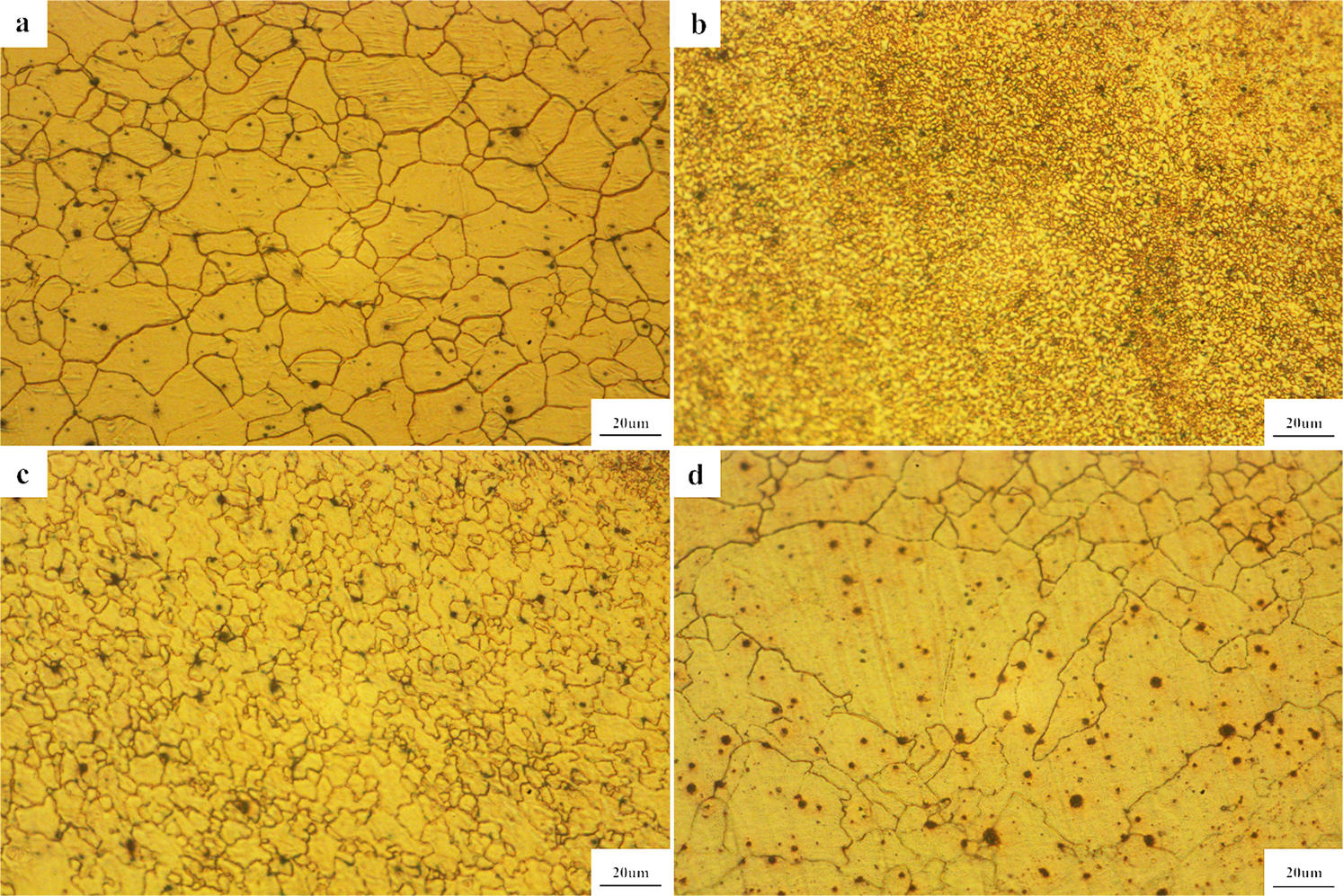
a BM; b SZ; c TMAZ; d HAZ
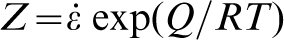
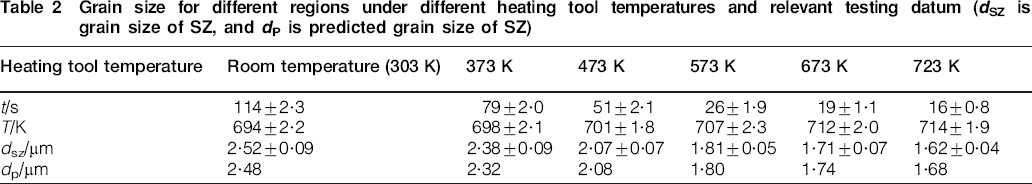
The grain size for different regions under different heating tool temperatures and the correlative testing datum are tabulated in Table 2. Obviously, owing to the improvement in the deformability of magnesium at higher temperature, as the heating tool temperatures rose, the temperature T in the SZ experienced an increased while the time t reduced. Table 2 also demonstrates that with the heating tool temperature increasing, the grains in the SZ got finer, which resulted in more drastic deformation. The refinement of the grains in the SZ was attained through the continuous dynamic recrystallisation taking place in the SZ. The fine dynamic recrystallised grain size developed in the SZ can be evaluated by a function of the Zenner–Hollomon parameter Z,22–24 which is presented below
 , in which Q is the activation energy of 164 kJ mol−1(Ref. 23) for AZ31 magnesium alloy, R is the ideal gas constant, T is the highest temperature the ZS experienced when plunging the tool and
 is the strain rate when plunging the tool, which could be obtained by the quotient of the deformation strain and
 times the plunging time, namely,
 , and A is a constant, which was calculated to be ∼1·7045×1011 μm3 s−1. When the value of
 is low and the initial grain size is large, the value of m is 3.
24
Because the welding tool used in this work has no thread profile on the probe pin, the rotational deformation was out of consideration. According to Yang et al.,
25
the SZ that is produced by the unthreaded welding tool is mainly composed of the material that is extruded out from the bottom of the keyhole. Hence, the strain in this experiment is defined by the plunging depth, and it is considered as a constant. According to above function, under the corresponding heating temperature, the predictions of dynamic recrystallised grain size are 2·48, 2·32, 2·08, 1·80, 1·74 and 1·68 μm respectively, which are very close to the experimental grain size (as shown in Table 2).
is low and the initial grain size is large, the value of m is 3.
24
Because the welding tool used in this work has no thread profile on the probe pin, the rotational deformation was out of consideration. According to Yang et al.,
25
the SZ that is produced by the unthreaded welding tool is mainly composed of the material that is extruded out from the bottom of the keyhole. Hence, the strain in this experiment is defined by the plunging depth, and it is considered as a constant. According to above function, under the corresponding heating temperature, the predictions of dynamic recrystallised grain size are 2·48, 2·32, 2·08, 1·80, 1·74 and 1·68 μm respectively, which are very close to the experimental grain size (as shown in Table 2).
Grain size for different regions under different heating tool temperatures and relevant testing datum (dSZ is grain size of SZ, and dP is predicted grain size of SZ)
Mechanical properties
Tensile shear load
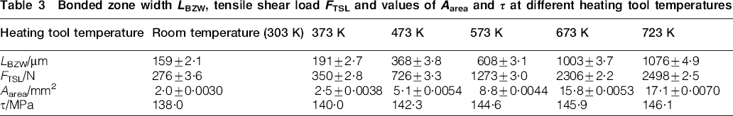
With an increase in the heating tool temperature, a higher heat input provided a longer time for the interface between the upper and bottom plates to react with each other, resulting in a broader bonded zone (as shown in Table 3). Table 3 shows that the rising tensile shear load is in companion with the decreasing grain size in the SZ and the increasing bonded zone width. Under a higher temperature, the deformability of the material was improved, and the deformation resistance decreased. When the welding tool exerted a downward force on the upper plate, the upper and bottom plates contacted tightly, which promoted diffusion of magnesium atom to achieve a high quality bonding. Because all the tensile testing joints failed by only interface shearing without pullout, in order to investigate its impact and contribution to the tensile shear load strengthening, a tensile shear load strength per unit area τ is proposed, which can be computed by the following formula
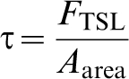
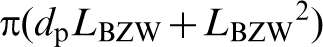 , dp is the diameter of the pin and LBZW is bonded zone width. Accordingly, the values of Aarea and τ at the different heating tool temperatures were calculated and are listed in Table 3. The τ increases as the heating tool temperature increases because of the grain refinement of the SZ. Figure 7 reveals the Hall–Petch relationship between the tensile shear load strength per unit area and the grain size of the SZ, which was in accord with the function of
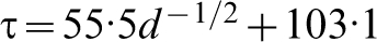 .
.
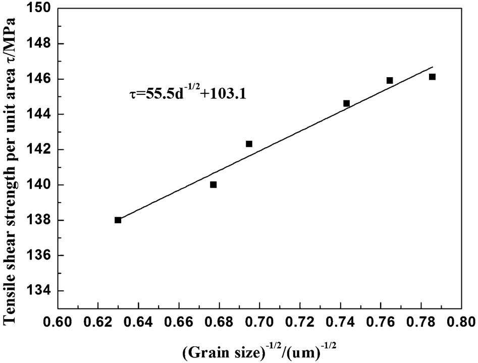
Hall–Petch relationship between tensile shear load strength per unit area and grains size of SZ
Bonded zone width LBZW, tensile shear load FTSL and values of Aarea and τ at different heating tool temperatures
Microhardness
Figure 8a shows the microhardness profiles of the FSSW welded joint (303 K) and HT-FSSW welded joint (take the weldment at 723 K as representative) at the transverse position, which at the distance of 1·5 mm from the surface of the upper sheet. From Fig. 8a, the microhardness of the BM (under the tool shoulder) of the HT-FSSW welded joints is higher than that of the FSSW welded joints because of the higher density of dislocation achieved under higher heating tool temperature. It is clear that a dense dislocation improves the microhardness of the alloys.
26
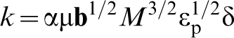
With an increase in the heating temperature, the microhardness of the SZ increased while that of the TMAZ decreased. This is because of the grain refinement of the SZ and the grain coarsening happening in the TMAZ of the HT-FSSW welded magnesium alloy joints. Figure 8c shows the slope of the Hall–Petch relationships of SZ and TMAZ. It can be found that the gradient of microhardness against the grain size of TMAZ is larger than that of the SZ. During the FSSW process, the SZ undergoes full recrystallisation, whereas the TMAZ goes through partial recrystallisation. Therefore, the density of dislocations that accumulated in the grain boundary is larger in the TAMZ than that in the SZ. According to the research by Godon et al.,
27
the slope k of the Hall–Petch relationship between microhardness and grain size is expressed by following equation
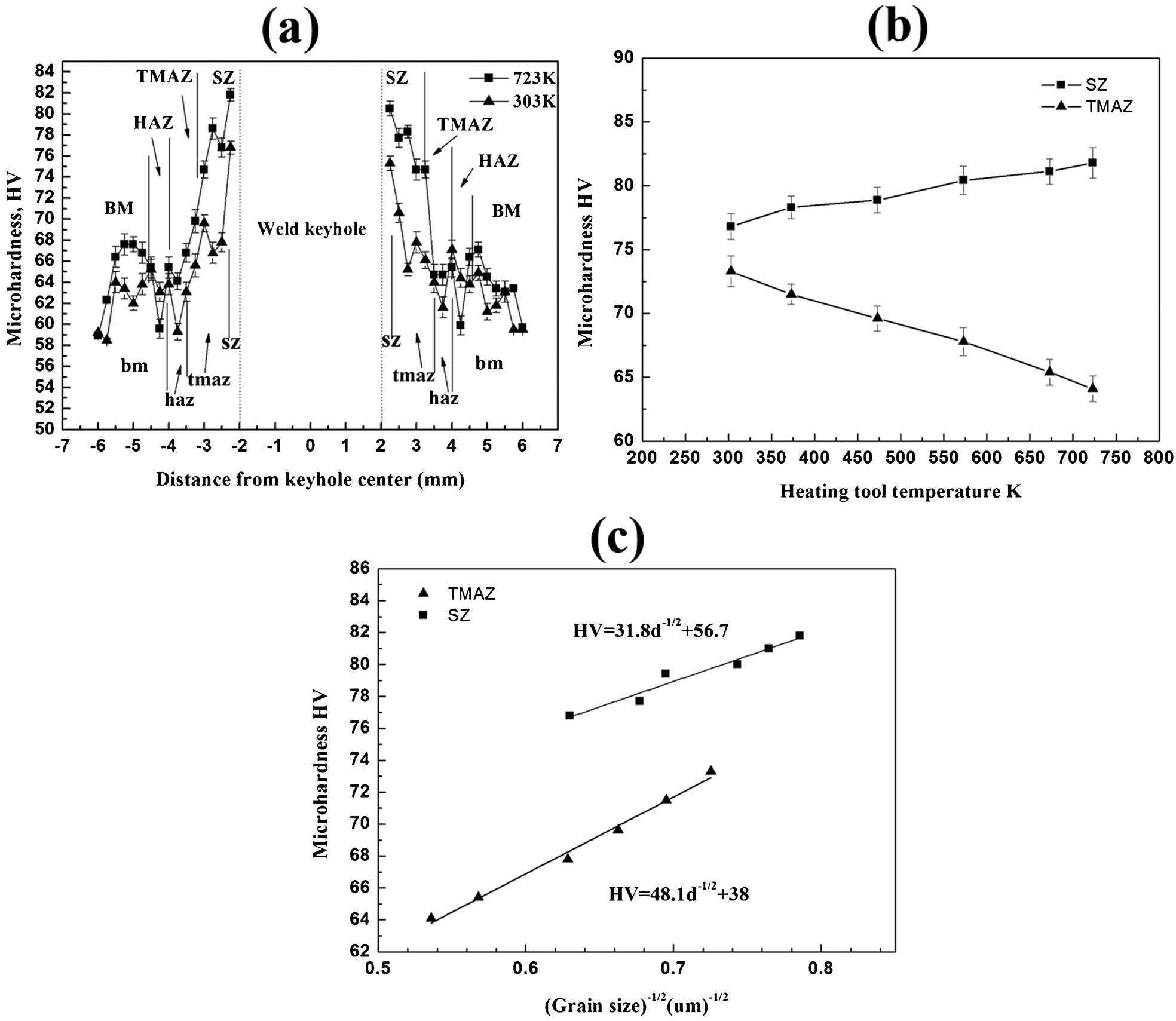
a microhardness distribution at transverse position for FSSW (303 K, marked by small letters)/HT-FSSW (723 K, marked by big letters) welded AZ31magnesium alloy joints, b relationships between microhardness of HT-FSSW welded joints and heating tool temperatures and c Hall–Petch relationships between microhardness and grain sizes of SZ and TMAZ
Conclusions
In this work, a new HT-FSSW welding process was developed, and its impacts on the microstructures and properties of the welded AZ31 magnesium alloy joints were investigated. The main conclusions were obtained as follows.
A more drastic recrystallisation reduced the grain size of the SZ of the HT-FSSW welded joints due to a more intense plastic deformation under higher heating tool temperature. Moreover, the increasing heating tool temperature coarsened the grains of the TMAZ and augmented the bonded zone width because of more heat input.
With an increase in heating temperature, enhancement of the tensile shear load strength per unit area was achieved because of the grain refinement of the SZ.
As the heating tool temperature increased, the microhardness of the SZ increased, whereas that of the TMAZ decreased due to the grain refinement of the SZ and the grain coarsening of the TMAZ. Because the density of dislocations that accumulated in the grain boundary is greater in the TMAZ than that in the SZ, the slope of the Hall–Petch relationship between microhardness and grain size of the TMAZ is greater than that of the SZ.
Footnotes
Acknowledgements
This project was financially supported by the Natural Science Foundation of China (grant no. 51375511) and the Fundamental Research Funds for the Central Universities of China (grant nos. CDJZR12138801, CDJZR11135501 and CDJZR13130033).