
Abstract
Laser brazing was carried out for dissimilar joining of sialon and a WC–Co alloy. Eutectic type Ag–Cu alloys as filler metals with different Ti content ranging from 0 to 2·8 mass-% were used to investigate the effects of Ti on the interface structure and strength of the joint. The filler metal sheet was sandwiched between a sialon block and a WC–Co alloy plate, and a laser beam was irradiated selectively on the WC–Co alloy plate. The brazed joint was obtained using the filler metal containing >0·3 mass-%Ti. TiN, Ti5Si3, and Cu4Ti layers were formed at the interface of sialon and brazed metal as compound layers. The shear strength of the brazed joint increased with increasing Ti content in the filler metal in the range 0·3–1·7 mass-%, reaching a maximum value of 106 MPa. However, the strength decreased when the Ti content became higher than 1·7 mass-%.
Introduction
Brazing is a suitable process for joining dissimilar materials, especially those that cannot be easily joined by fusion welding, such as ceramics and metals.1–13 Laser brazing, which is a novel brazing technique, uses laser beam irradiation to selectively heat a specific part of the components to be joined. Compared to conventional furnace brazing, laser brazing can potentially minimise material deterioration and excess growth of the brittle compound layer formed during brazing because the heating and cooling times in this process are short, and only the selected part of the component
Sialon is an engineering ceramics comprising mostly Si3N4. It has several functional characteristics such as high strength, high hardness, high resistance to corrosion and wear, and low thermal expansion.1–4 However, it is difficult to braze sialon to other materials without the use of an activated filler metal or some type of surface treatment because the wettability of sialon and the molten filler metal plays a crucial role in the brazing of these materials.2–5, 16–18 Studies have been conducted to investigate the brazing of sialon using an activated filler metal,1–6, 8, 9, 16–21 and the behaviours of an active element and the molten filler metal in the conventional furnace heating process are well known.
The active element (e.g. Ti, Zr or Cr) in the filler metal improves the wettability of sialon and the molten filler metal and reacts with Si and N in Si3N4, which is the base material of sialon.1–8, 17, 18 Wettability improves with increasing active element content in the filler metal; the increased wettability, in turn, increases the joint strength.7–11 However, depending on the brazing temperature and time, an increase in the active element content causes a decrease in the joint strength, regardless of the improvement in wettability because of the formation of a thick brittle compound layer, whose thermal expansion coefficient has a large mismatch with that of sialon.1–3, 20–23 These problems arise because conventional furnace brazing requires a long treatment lasting several hours in order to ensure heating and cooling of the entire component. These problems are suppressed in laser brazing owing to short heating and cooling periods of only a few minutes. However, there is limited information on the effect of the active element content on the dissimilar brazing of short heating durations, such as laser brazing.11–13 Based on this information, the objective of this study was to determine the effect of Ti (as an active element in the filler metal of a dissimilar laser-brazed joint of sialon to the WC–Co alloy) on the interface structure and strength of the joint; the WC–Co alloy was selected as a counter material owing to its low thermal expansion coefficient and relatively high heat resistance.
Experimental methods
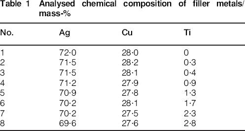
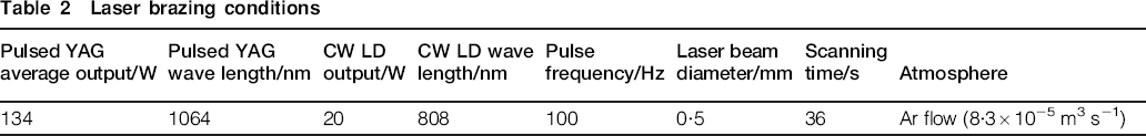
Experiments were carried out using sialon blocks, WC–Co alloy plates, and eight types of Ag–Cu–Ti filler metal sheets with different Ti content. The blocks of sialon, SAN-2 (>90 mass-%Si3N4), had dimensions 5×5×3·5 mm. The WC–Co alloy plates, which were classified as ISO K10 grade (WC–6 mass-%Co), were used as substrates with dimensions 10×10×2 mm. Table 1 lists the analysed chemical compositions of the filler metals, which were eutectic type Ag–Cu alloys containing additional Ti as an active element, with the Ti content ranging from 0 to 2·8 mass-%. An ingot of the tentative alloy of the filler metal was prepared by the vacuum fusion method; the ingot was then cold rolled into a sheet with dimensions 20×100×0·1 mm. From this sheet, another smaller 3×3 mm square sheet with a thickness of 0·1 mm was cut. The size of the filler metal sheet was selected such that the filler metal could be prevented from flowing out of the joint interface and forming a fillet. Before brazing, all materials were degreased by ultrasonic agitation in acetone for 10 min and dried in air. Figure 1 shows a schematic illustration of the laser brazing apparatus. The specimen was shaped like a top hat, where a filler metal sheet was sandwiched between the sialon block and WC–Co alloy plate. The specimen was then placed in a vacuum chamber. The top of the specimen was covered with a transparent quartz glass plate, which acted not only as a window of the vacuum chamber for laser beam irradiation but also held the specimen in place. A pressure of 3·4 MPa was applied to the filler metal through the sialon block and quartz glass plate so as to prevent the specimen from moving. The vacuum chamber was evacuated to less than 10−1 Pa, and 99·999% pure Ar gas at atmospheric pressure was supplied to the chamber after the evacuation. This evacuation–substitution cycle was performed five times before brazing. During brazing, Ar gas continued to flow at a rate of approximately 5 L min−1. YAG and LD laser beams were coaxially transferred with an optical fibre to the laser head unit and irradiated through the transparent quartz glass plate to the top side of the WC–Co alloy plate at an irradiation angle of 85°. The laser brazing conditions are summarised in Table 2. The WC–Co alloy plate was selectively subjected to laser irradiation for 36 s around the periphery of the sialon block. The laser beam diameter was 0·5 mm and the scanning speed of the laser was 0·78 mm s−1. During laser heating, the temperature of the WC–Co alloy plate was monitored by an R-type thermocouple inserted into a hole beneath the joint on the lower surface of the plate.
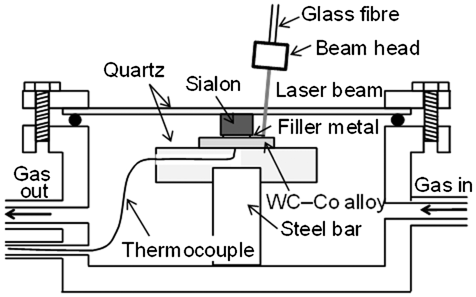
Schematic illustration of laser brazing apparatus
Analysed chemical composition of filler metals/mass-%
Laser brazing conditions
The brazing joint specimens were cross-sectioned and mounted in an epoxy resin before being ground with a no. 220 SiC paper and polished with a diamond paste. Observations of the microstructure of the brazed interface and its elemental analysis were then performed using scanning electron microscopy (SEM), transmission electron microscopy (TEM), and energy-dispersive X-ray spectrometry (EDS).
A shear strength test of the joint was carried out using a precision universal tester operated at a cross-head speed of 0·5 mm min−1. Five joints were tested for each of the eight types of filler metals listed in Table 1. Figure 2 shows a schematic illustration of the shear strength test. The WC–Co alloy plate was clamped, and the sialon block was loaded by the steel jig. The shear strength was calculated as the maximum load divided by the joining area, which was estimated from the fractured surface. The fractured surface was analysed using optical microscopy (OM) and X-ray diffractometry.
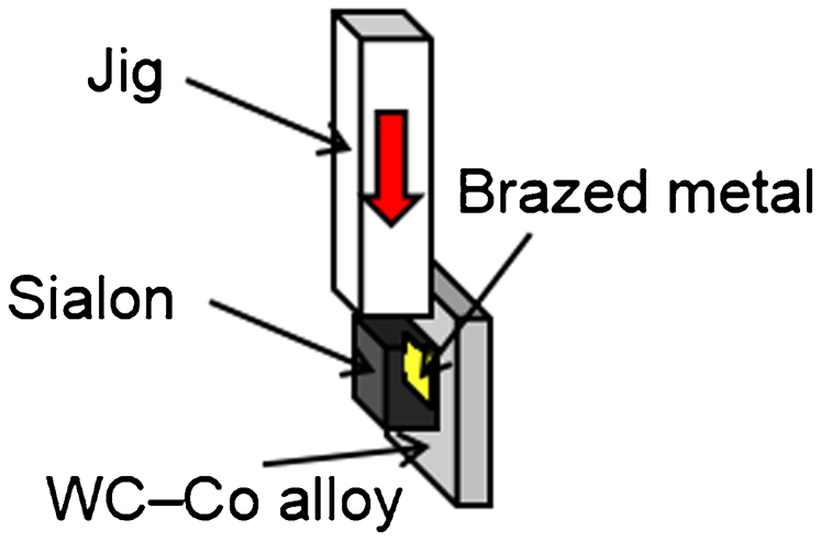
Schematic illustration of shear strength test
Results and discussion
Thermal history of laser heating and brazed joint appearance
Figure 3 shows a typical temperature profile of the WC–Co alloy plate during laser brazing. The highest temperature reached was 1115 K, which was more than the melting temperature of the filler metal (approximately 1073 K). Figure 4 shows the appearance of the laser brazed joint obtained using a filler metal containing >0·3 mass-%Ti. However, when a filler metal without Ti was used, the sialon block and brazed metal could not be joined, proving that additional Ti served as an active element for the filler metal enabled joining of sialon and the WC–Co alloy. In contrast, the WC–Co alloy plate and brazed metal were joined even without Ti. Macrocracking was not observed in any of the brazed joints.
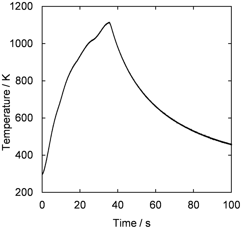
Typical temperature profile of WC–Co alloy plate during laser brazing
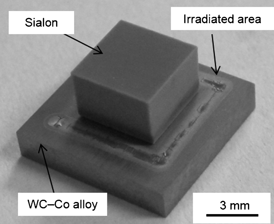
Appearance of laser brazed joint
Microstructure of brazed joint
Figure 5 shows the secondary electron images (SEIs) and elemental distributions of Ti and Cu in the cross-sections of the brazed joints of sialon and brazed metals containing 0·3, 1·7 and 2·8 mass-%Ti. The upper side of each SEI corresponds to sialon while the lower side corresponds to the brazed metal. A compound layer was observed at the interface of sialon and the brazed metal. Si and N in sialon and Ag and Cu in the brazed metal were the major components of each material. The interfacial compound layer was identified as a Ti concentrated layer. Using the filler metals containing 1·7 and 2·8 mass-%Ti, a part of the Ti concentrated layer including Cu and the denuded zone of Cu were observed in the brazed metal adjoining the Ti concentrated layer. The observations suggest that as an active element in the filler metal, Ti reacted with sialon at the joint interface during laser heating. The thickness of the Ti concentrated layer increased from about 0·1 to 1·8 μm with an increase in the Ti content from 0·3 to 2·8 mass-%. Figure 6a and b shows TEM bright field images (BFIs) at the joint interface between sialon and the brazed metal containing 0·3 and 1·7 mass-%Ti respectively. The compound layer was observed at the interface between sialon and the brazed metal for each case. However, for the filler metal containing 0·3 mass-%Ti, the compound layer was thin and discontinuous because it was interrupted by the unjoined area. In contrast, a thick and continuous compound layer was observed for the filler metal with 1·7 mass-%Ti. Figure 7 shows the TEM BFIs and elemental distributions of Si, N, Ti, Cu and Ag measured in the area shown by the broken line in Fig. 6b. Figure 7 also shows the phases detected by the selected area diffraction analysis at each position. The microstructure at the interface was divided into four regions, depending on the dominant constitutional elements at each position: Si and N at position 1, Ti and N at position 2, Ti and Si at position 3, and Ti and Cu at position 4. The selected area diffraction patterns corresponding to positions 1–4 were found to be those for Si3N4, TiN, Ti5Si3 and Cu4Ti respectively. These results indicate that the Ti concentrated layer formed at the interface comprised multiple thin layers of first TiN, then Ti5Si3, and finally Cu4Ti, in that order from sialon side. This compound layer is considered to be formed because Ti in the filler metal has a high affinity for Si and N in sialon, which mainly consists of Si3N4; thus, it diffused to the interface and formed thin intermetallic compound layers. The formation of TiN and Ti5Si3 is thermodynamically favourable because the free energy for the reactions Si3N4+4Ti→4TiN+3Si and 5Ti+3Si→Ti5Si3 is approximately −550 and −205 kJ respectively at 1173 K. 6 In addition, as the major alloying element of the filler metal, Cu also has a high affinity for Ti. Therefore, Ti formed a layer comprising Cu4Ti after the formation of TiN and Ti5Si3, which also resulted in the formation of the denuded zone of Cu. Figure 8 shows the relation between the Ti content and thickness of the TiN and Ti5Si3 layers, which were formed by the reactions between Si and N in sialon and Ti in the filler metal, of the brazed joint as measured by the TEM observation. The thickness of the TiN and Ti5Si3 layers increased with increasing Ti content as well as the Ti concentrated layer thickness as shown in Fig. 5. The thickness of the TiN and Ti5Si3 layers of the brazed joint formed using the filler metal containing 1·7 mass-%Ti was approximately 100–200 nm. On the other hand, the thickness of a similar layer formed by conventional furnace brazing was reported to be approximately 4·7 μm. 4 This large difference in thickness could be explained by the difference in heating and cooling times between laser brazing and conventional furnace brazing.
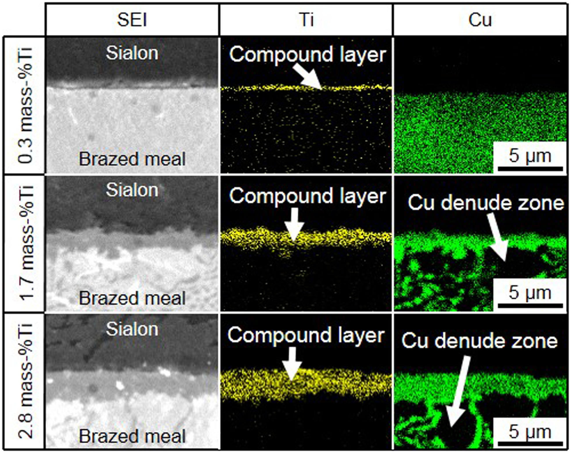
Secondary electron image and elemental distributions of Ti and Cu at brazed joints of sialon and brazed metals containing 0·3, 1·7 and 2·8 mass-%Ti
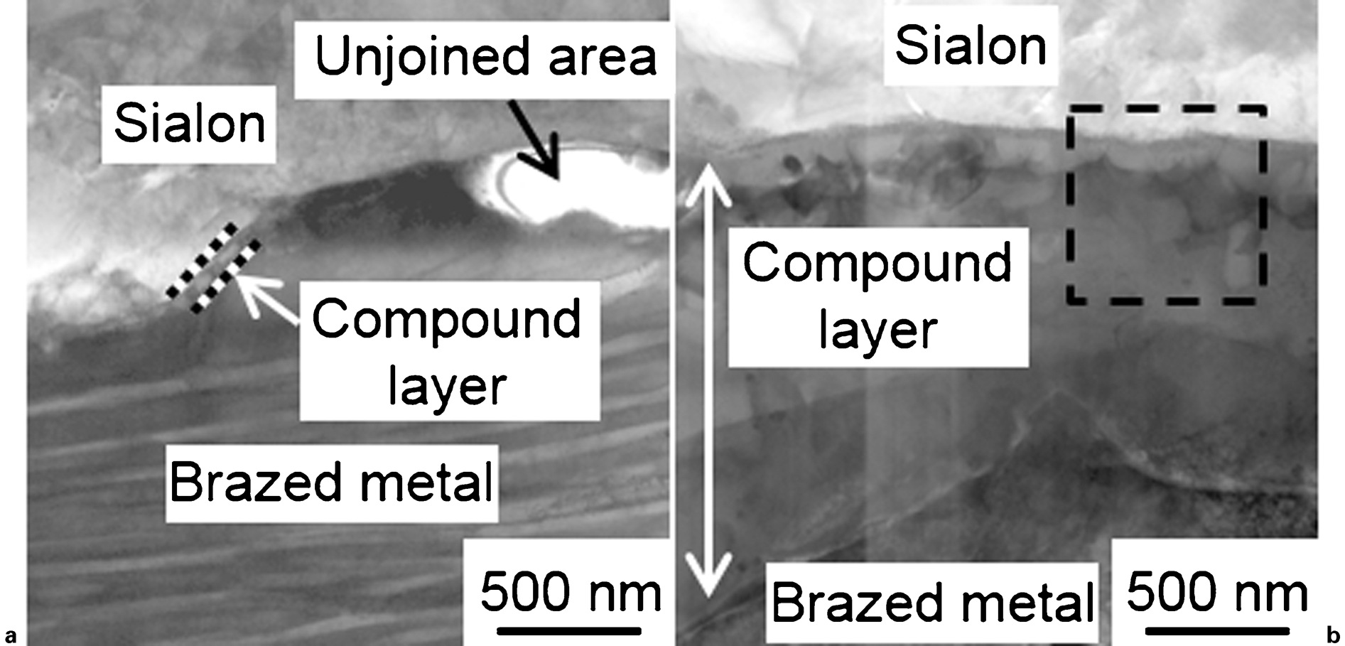
TEM bright field images at joint interface between sialon block and brazed metals containing a 0·3 and b 1·7 mass-%Ti
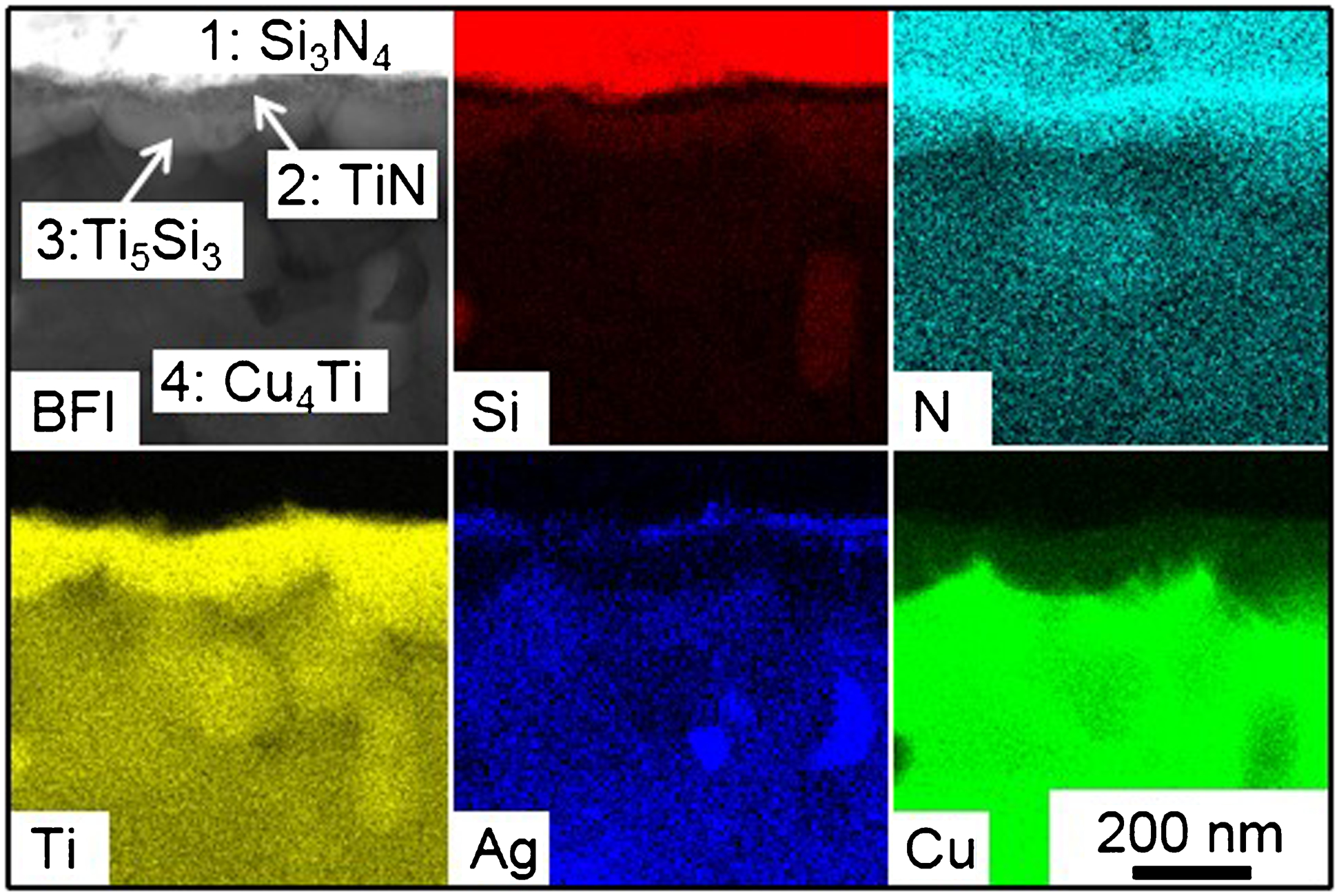
TEM bright field image and elemental distributions of Si, N, Ti, Cu and Ag measured in area shown by broken line in Fig. 6b
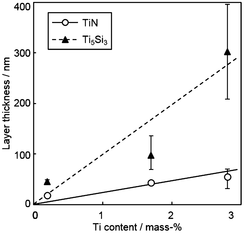
Relation between Ti content and thickness of TiN and Ti5Si3 layers of brazed joint as measured by TEM observation
Strength of brazed joint
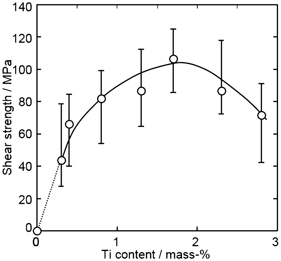
Figure 9 shows the effect of the Ti content on the shear strength of the brazed joint. The shear strength increased as the Ti content increased up to 1·7 mass-%, and then decreased when the Ti content increased from 1·7 to 2·8 mass-%Ti. From macroscopic fractured surface observation, the brazed metal could be observed only on the WC–Co alloy plate side in each filler metal, indicating that a fracture occurred at the interface of the sialon block and brazed metal, including the compound layer between them. In order to identify the phase existing on the fractured surface, X-ray diffraction analysis was carried out on the central region of the fractured surfaces of the sialon and WC–Co alloy sides for the brazed joint formed using the filler metal containing 1·7 mass-%Ti. Table 3 lists the identified phases and their detected intensities. The diffraction pattern of TiN was not identified because the TiN layer was too thin to be detected and also because this pattern overlapped with other diffraction patterns. Si3N4, and Ag and Cu were the major component phases of sialon and the filler metal respectively. However, Si3N4 was detected even on the WC–Co alloy side despite the fact that its intensities were weak. In addition to these phases, Ti5Si3 and Cu4Ti were detected as reaction compound phases. Moreover, Ti5Si3 was detected on both fractured surfaces; however, Cu4Ti was detected only on the fractured surface of the WC–Co alloy side. These results indicated that a fracture occurred mainly in the compound layer of Ti5Si3. When the filler metal containing lower Ti content (<1·7 mass-%) was used, the compound layer was not formed continuously at the interface. Thus, a fracture occurred along the unjoined interface and in the Ti5Si3 and/or TiN compound layers. Therefore, the joint shear strength increased when the Ti content was increased in the filler metal because of the increase in the formation ratio of the compound layer at the interface. The proper Ti content in the filler metal was approximately 1·7 mass-%, which enabled the continuous formation of a comparatively thin compound layer at the interface. Using the filler metal containing higher Ti content (>1·7 mass-%), the thickness of the compound layer increased with increasing Ti content, which decreased the fracture strength. Possible reasons for the decrease in the fracture strength due to the formation of a thick brittle compound layer have been reported to be an increase in the ratio of small defects such as microcracking and voids20, 21 in the brittle compound layer and increase in residual stress.2, 3, 23
Effect of Ti content on shear strength of brazed joint
Identified phases and their intensities detected on fractured surfaces of sialon and WC–Co alloy sides of brazed joint by using filler metal containing 1·7 mass-%Ti
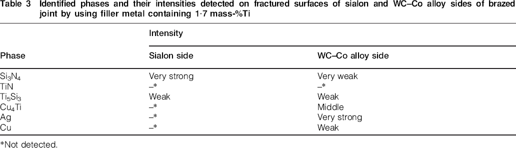
Not detected.
Conclusions
Laser brazing was carried out for dissimilar joining of sialon to the WC–Co alloy by using an Ag–Cu–Ti alloy as the filler metal. Filler metals containing 0–2·8 mass-%Ti were used to investigate the effects of Ti as an active element on the interface structure and shear strength of the brazed joint. We arrived at the following conclusions.
Ti serving as an active element in the Ag–Cu filler metal enabled the joining of sialon and the WC–Co alloy via laser brazing, which allowed selective heating for a short duration.
A Ti concentrated layer was formed at the interface between sialon and the brazed metal. This compound layer comprised multilayers of first TiN, then Ti5Si3, and finally Cu4Ti, in that order from sialon side. Moreover, the thickness of these compound layers increased with increasing Ti content in the filler metal.
The shear strength of the laser brazed joint increased with increasing Ti content in the range 0·3–1·7 mass-%; however, Ti content higher than this range decreased the shear strength of the joint.
The diffraction patterns of Si3N4 and Ti5Si3 were detected on the fractured surfaces of both the sialon and WC–Co alloy sides, while the diffraction pattern of Cu4Ti was detected only on the fractured surface of the WC–Co alloy side.