






Abstract
Phase transformations in dissimilar resistance spot welds of dual phase steel and ferritic stainless steel are analysed. In contrast to a full martensitic microstructure predicted by the Schaeffler and Balmforth diagrams, a ferrite–martensite microstructure was observed in the fusion zone. The formation of ferrite phase in the fusion zone can be attributed to the rapid cooling rate of resistance spot welding, which suppresses the post-solidification ferrite–austenite transformation. The grain growth and martensite formation were main metallurgical features of the heat affected zone of ferritic stainless steel side. Microstructure gradient of heat affected zone in dual phase steel side was dictated by martensitic transformation. The effect of weld thermal cycle on the mechanical performance of the joint is discussed.
Keywords
Introduction
Resistance spot welding (RSW) is a critical joining process in vehicle production. Vehicle crashworthiness, which is defined as the capability of a car structure to provide adequate protection to its passengers against injuries in the event of a crash, largely depends on the integrity and the mechanical performance of the spot welds.1–3
Mechanical properties and failure behaviour of the spot welds depend on the weld metallurgical characteristics. It is shown that the hardness characteristics is the key controlling factor in interfacial to pullout failure mode transition of resistance spot welds, which in turn is governed by weld phase transformations.4–10 Rapid heating and cooling induced by RSW thermal cycles can significantly alter microstructure of the weldment: fusion zone (FZ) undergoes melting and resolidification, while heat affected zone (HAZ) often experiences solid state phase changes but no melting. Therefore, studying the phase transformations in FZ and HAZ is critical for understanding the failure mode behaviour and mechanical properties of the joints.
An unavoidable practical requirement in modern vehicle construction technology is dissimilar welding. Owing to mixing of the base materials in the FZ, which can affect the phase transformations in the weld nugget and complicated microstructure gradient across the FZ and HAZs coupled with the heterogeneity in mechanical properties (strength, ductility and workhardening) of the base metals (BMs), the weldability of dissimilar welds can be problematic compared to similar welds.11–14 Joining of stainless steels and carbon steels is an interesting issue in welding community. Although welding metallurgy of dissimilar stainless steels joints during arc welding processes is well researched, there are limited publications on their resistance spot weldability. Poggio et al. 15 studied the effect of RSW parameters on the weldability of dissimilar DP600/AISI 304 joint. Alenius et al. 16 studied the weldability of various dissimilar metal joints between austenitic stainless steels and non-stainless steels. They concluded that the strength of dissimilar joint in the tensile shear test is dictated by the strength and thickness of non-stainless steels. Pouranvari and Marashi 14 found that failure mode of dissimilar spot welds of low carbon steels and 304 stainless steel is controlled by the hardness of the FZ, which in turn is governed by the dilution between two BMs, hardness and the FZ size of low carbon steel sheet.
Nowadays, ferritic stainless steels (FSS) are widely used in structural frameworks and body panelling of buses and coaches. Since advanced steel (e.g. dual phase steels) are also considered for vehicle production, dissimilar RSW of both steels is an unavoidable practical requirement in modern vehicle design. Improving knowledge regarding the microstructural characteristics and failure behaviour is a priority for the successful implementation of new design in vehicle applications. To the best knowledge of the authors, there is no publication on the dissimilar resistance spot weldability of FSS and dual phase steels. Therefore, the present paper aims at investigating the welding metallurgy of dissimilar RSW of AISI 430 FSS and DP600 advanced high strength dual phase steel. The results of this study showed that high cooling rates of RSW process has a profound influence on the microstructure evolution in the FZ, thus making it impossible to predict the microstructure of the weld nugget from the conventional constitution diagrams (e.g. Schaffler and Balmforth diagrams). The phase transformations in FZ and HAZ induced by RSW process are analysed. Moreover, the effects of weld physical and metallurgical characteristics on failure mode and mechanical properties of the welds are discussed.
Experimental
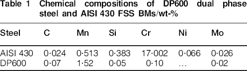
A galvanised DP600 dual phase steel sheet and an FSS AISI 430 sheet were used as the BMs. The sheet thickness of both BMs was 1·5 mm. Tables 1 and 2 show the chemical compositions and tensile properties of DP600 and FSS BMs.
Chemical compositions of DP600 dual phase steel and AISI 430 FSS BMs/wt-%
Mechanical properties of DP600 dual phase steel and AISI 430 FSS BMs

RSW was performed using a 120 kVA AC pedestal type RSW machine operating at 50 Hz controlled by a programmable logic controller. Welding was conducted using a 45 deg truncated cone resistance welding manufacturing alliance class 2 electrode with 8 mm face diameter. Squeeze time, welding time, electrode holding time after current off and electrode force were kept constant at 0·9, 0·3, 0·2 s and 4·5 kN respectively. Welding current was incrementally increased from 6 to 12 kA with a step size of 0·5 kA.
The samples for the quasi-static tensile shear test were prepared according to American Welding Society D8·1M standard. 17 The tensile shear tests were performed at a crosshead of 2 mm min−1. Mechanical performance of the welds was described in terms of peak load Pmax and failure energy Wmax. Failure modes were determined by observing the weld fracture surfaces.
Samples for metallographic examination were prepared using standard metallography procedure. Optical microscopy was used to examine the microstructures of the joints. Marble etchant (10 g CuSO4, 50 mL HCl, 50 mL H2O) was used for macrostructural examination. Moreover, nital (100 mL C2H5OH, 2 mL HNO3) and Kalling's no. 1 (33 mL H2O, 1·5 g CuCl2, 33 mL HCl, 33 mL C2H5OH) reagents were used for microstructural metallography of DP600 and FSS sides respectively. Fusion zone size of the spot welds was measured using optical microscope. Vickers microhardness test was performed using an indenter load of 100 g for a period of 20 s to obtain diagonal hardness profile. The hardness indentations were spaced 0·3 mm apart. The microhardness traverses were performed on a diagonal covering BMs, HAZ and FZ. The line of hardness measurement is indicated in Fig. 1a.
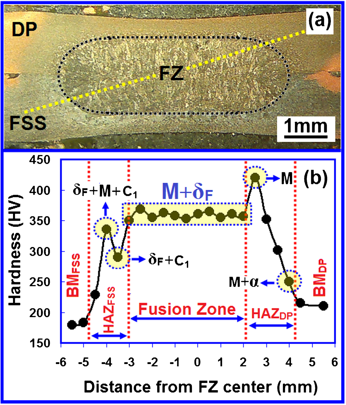
Typical a macrostructure and b hardness profile of DP600/FSS resistance spot welds; corresponding welding current is 7·5 kA; line of hardness measurement is indicated in a; corresponding microstructures are labelled on hardness profile (M: marteniste; δF: delta ferrite; α: alpha ferrite; C1: carbide)
Results and discussion
Metallurgical characteristic
Metallurgical/hardness characteristics of the spot welds play important roles in their failure mode and mechanical properties. Figure 1a and b shows a typical macrostructure and the corresponding hardness profiles of DP600/FSS welds made at welding current of 7·5 kA, indicating microstructural gradient across the weldment.
Fusion zone
The hardness of the FZ averaged at 350 HV is higher than the hardness of the BMs. Figure 2a and b shows the optical and SEM images of the FZ microstructure, indicating a ferrite–martensite dual phase microstructure. Microstructural evolution in FZ is governed by chemical composition and cooling rate during RSW process:
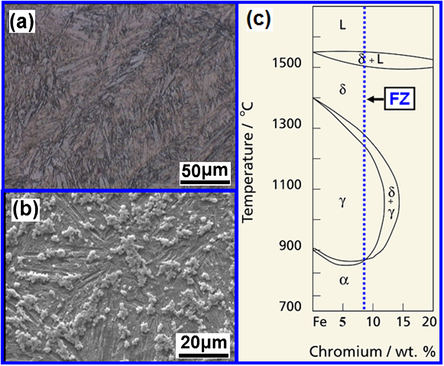
a optical and b SEM images showing microstructure of FZ of DP600/FSS resistance spot welds made at welding current of 7·5 kA and c Fe–Cr phase diagram; 21 chemical composition of FZ is superimposed on diagram
(i) fusion zone chemical composition
The chemical composition of the FZ is affected by the chemical composition of the BMs involved in the joints and the mixing of them. The FZ chemical composition of dissimilar combination can be estimated by averaging the FSS and DP600 BM if, for the sake of simplicity, the same melting ratio is assumed for both BMs. Therefore, the chemical composition of dissimilar DP600/FSS FZ is estimated as Fe–0·047C–1·01Mn–0·21Si–8·55Cr–0·03Ni–0·023Mo.
(ii) cooling rate
The heating and cooling rates of RSW process are significantly higher than conventional arc welding and laser welding processes. 18 The time to cool from 800 to 500°C (Δt8–5) is ∼8 s for shielded metal arc welding of a thick steel plate with a heat input of 2 kJ mm−1. 19 However, Δt8–5 for 0·8 mm thick sheet spot welds is reported to be only ∼0·06 s. 20 According to Gould's calculations, the cooling rate in RSW of 1·5 mm thick steel sheet is ∼4000 K s−1. These extremely high cooling rates are due to the presence of water cooled copper electrodes and their quenching effect as well as short welding cycle. This high cooling rate can significantly affect the phase transformations of the weld, as explained below.
Fuzion zone microstructure of dissimilar FSS/DP600 spot welds can be predicted by constitution diagrams such as Schaeffler diagram
21
and Balmforth and Lippold diagrams.
22
Aforementioned diagrams (not shown here) predict a fully martensitic microstructure of the FZ. However, as mentioned above, the presence of ferrite phase is evident in the FZ. This contradiction can be explained by describing the microstructure development sequence in the FZ. Considering the low carbon content of the FZ, its phase transformation can be explained using Fe–Cr binary phase diagram
23
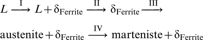
(Fig. 1c). According to Fig. 1c, the phase transformations sequence is as follows

According to the aforementioned transformations sequence, during fast cooling of welding, the austenite formed during stage III will be transformed to non-equilibrium martensite phase on stage IV. However, the rapid solidification of RSW affects the ferrite to austenite transformation (stage III). At rapid solidification, δFerrite→austenite transformation has less time to occur. Therefore, some amount of untransformed ferrite is retained in the microstructure after stage III. Therefore, the phase transformation under rapid cooling rates of RSW can be considered as follows
Heat affected zone
Heat affected zone of dual phase steel
Figure 3a shows Fe–C phase diagram that can be used as a reference to track phase transformation in the HAZ of DP600 steel during welding. Figure 3b shows optical micrograph of the HAZ, indicating a gradient in microstructure due to temperature gradient in the HAZ. The HAZ of DP600 steel is divided into two distinct subregions: upper critical HAZ (UCHAZ) and intercritical HAZ (ICHAZ):
UCHAZ: Fig. 3c shows microstructure of UCHAZ, indicating a full martensitic microstructure. The hardness of UCHAZ near the FZ is 400 HV, which is about two times higher than that of the DP600 BM. This region experiences peak temperatures above Ac3 transforming BM microstructure into austenite. 24 In coarse grained region, which is adjacent to the FZ, both high cooling rate and large austenite grain size coupled with the formation of the carbon rich austenite promote the formation of the martensite.
ICHAZ: Figure 3d shows microstructure of ICHAZ, indicating a dual phase microstructure of martensite and ferrite. In this region, the peak temperature ranges between Ac1 and Ac3 and the BM microstructure transforms into ferrite plus austenite during heating. 24 The hardenability of the intercritically formed austenite is higher than the initial hardenability of the steel due to carbon partitioning during intercritical austenisation. Owing to the fast cooling rate, austenite is transformed subsequently into the martensite.
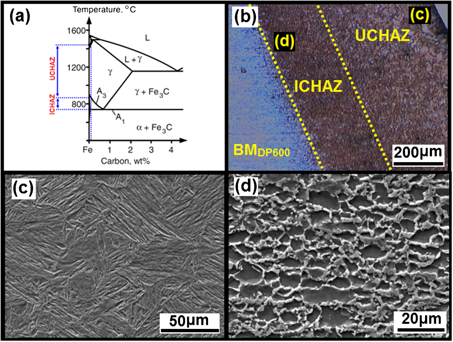
a Fe–C phase diagram; b optical micrograph showing microstructure gradient in HAZ of DP600 side in welds made at welding current of 7·5 kA; c SEM image showing martensite lath in UCHAZ near FZ; d SEM image showing ferritic–martensitic microstructure of ICHAZ
It is of note that no softening is detected in the HAZ/BM interface. HAZ softening is generally observable in the dual phase steel containing higher martensite volume fraction (e.g. DP780 and DP980). 1
Heat affected zone of FSS
Figure 4a shows vertical section of Fe–Cr–C phase diagram at 17%Cr, which can be used as a reference to track phase transformations in the HAZ of AISI 430 steel during welding. Figure 4b shows an optical micrograph showing the microstructure gradient in the HAZ of the FSS side. The phase transformations in the HAZ of AISI 430 steel welds have been discussed elsewhere. 25 Two major phenomena dictate the microstructure transformation in the HAZ including grain growth and martensite formation (see Fig. 4c and d). It can be seen that the grain growth is inversely proportional to the distance from the fusion line. Depending on the temperature experienced during heating cycle of the welding, the microstructure of HAZ can either be almost fully ferrite (see Fig. 4c) or a mixture of ferrite and martensite at grain boundaries (see Fig. 4d). At higher temperature HAZ, in the absence of high temperature austenite, ferrite grains grow quite rapidly and the HAZ exhibits large ferrite grains. At lower temperature HAZ, where the austenite is stable in the microstructure at elevated temperature, it can inhibit ferrite grain growth by pinning the grain boundaries. Upon cooling, any austenite that may be formed at elevated temperature will transform to martensite.
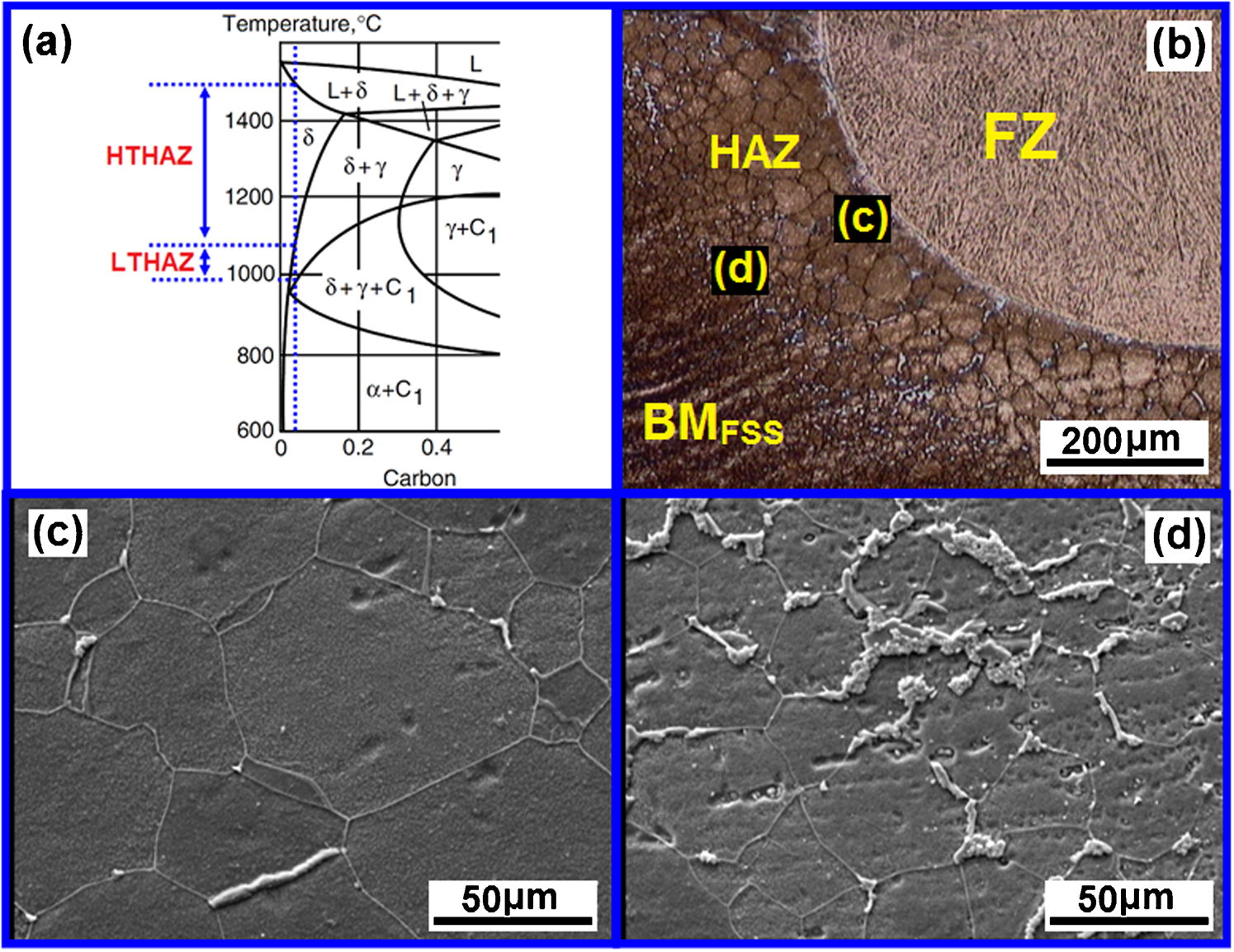
a Fe–17Cr–C phase diagram, b optical micrograph showing microstructure gradient in HAZ of FSS side of made at welding current of 7·5 kA, c SEM image showing grain growth at high temperature HAZ (HTHAZ) and d SEM image of low temperature HAZ (LTHAZ) showing ferritic grain structure with lower grain size and higher amount of martensite compared with HTHAZ
Mechanical performance
Failure mode
Failure modes of welds made under various welding conditions were determined by examination of the weld fracture surfaces (Fig. 5). Two failure modes were observed during the tensile shear tests including interfacial fracture, which is accompanied with crack propagation through FZ (Fig. 5a), and pullout mode, which is accompanied with nugget withdrawal from FSS side, the lower strength side (Fig. 5b).
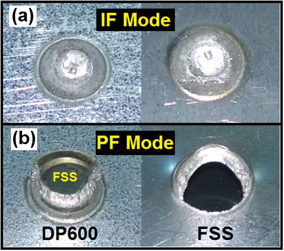
a interfacial fracture mode; b pullout fracture mode
The FZ size is the key physical weld attribute controlling the failure mode and mechanical properties of RSWs. 1 Figure 6a shows the effect of welding current on the FZ size, indicating that weld nugget enlarges with the welding current with the exception of high currents (>11·5 kA), which show a decrease in the FZ size due to expulsion. According to Fig. 6a, the failure mode was changed from IF to PF by increasing the welding current and FZ size. The minimum welding current required to ensure PF mode is 7 kA.
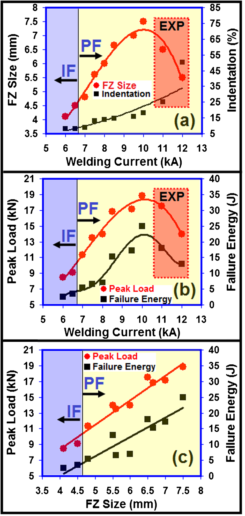
a effect of welding current on FZ size and electrode indentation depth, b effect of welding current on peak load and failure energy and c effect of FZ size on peak load and failure energy of DP600/FSS spot welds; failure modes of welds (IF versus PF) are indicated in figures; welds that experienced expulsion (EXP) during welding process are specified in a and b
Mechanical properties
To explore the quasi-static mechanical properties of the spot welds, peak load and energy absorption were measured. Figure 6b shows the effect of welding current on the peak load and energy absorption. The experimental results indicate that welding current has a significant effect on the load carrying capacity and energy absorption capability of the spot welds under the tensile shear static test. It is well established that there is an optimum welding current to achieve a high performance resistance spot weld.1, 26, 27 As can be seen, increasing welding current up to 10 kA improved mechanical properties of the welds. Increasing welding current and welding time results in higher heat generation at the faying interface, leading to the formation of larger FZ, and increases overall bond area. Moreover, increasing welding current beyond 6·5 kA promotes pullout failure mode versus interfacial failure mode, which can improve peak load and energy absorption. However, welding with welding currents over 10 kA decreased the peak load and energy absorption. High heat input welding conditions lead to increasing the probability of occurrence and extent of expulsion and the associated indentation. Reduction of peak load at high welding current and welding time can be attributed to the following reasons:
reduction of weld nugget size on expulsion (see Fig. 6a)
increasing electrode indentation on expulsion. Figure 6a shows the effect of welding current on the electrode indentation. As can be seen, increasing heat input increases the temperature of electrode/sheet interface, which in turn increases the degree of plastic deformation that can occur in the sheet surface under electrode pressure. It should be noted that spot welds with expulsion exhibit severe electrode indentation (Fig. 6a), which is accompanied by thinning and associated stress concentration. The surface indentation can change the stress state at the weld nugget edge, and deep surface indentations are expected to promote premature failure.
To examine the relationship between the peak load and the failure energy and the weld nugget size, a scatter plot of peak load (and failure energy) versus weld size was constructed (Fig. 6c). As can be seen, there is a general linear relationship between the peak load (and also failure energy) and the FZ size. It is well established that there is strong direct correlation of the tensile shear properties and FZ size for similar and dissimilar joints of both conventional and advanced steel resistance spot welds.1, 12–16, 26–30 The peak point in load–displacement plot of the tensile shear test corresponds to the point of crack propagation through the weld nugget for interfacial mode and to necking point at failure location (i.e. BM or HAZ) for pullout mode. For interfacial mode, the larger the nugget size, the higher is the interfacial resistance to shearing. For pullout mode, increasing nugget diameter increases the nugget resistance against rotating and therefore increases the required force for necking at failure location. In both cases, increasing FZ size increases the required force and energy for failure to occur.
Finally, it is interesting to note that the mixing of BMs during dissimilar welding and differences in plastic deformation behaviour of the BMs have a consequence on the failure behaviour of dissimilar welds. Therefore, it can be anticipated that mechanical properties and interfacial to pullout failure mode transition of dissimilar FSS/DP600 RSW is different from similar DP600/DP600 and FSS/FSS joints due to the differences in hardness characteristics of dissimilar and similar joints in conjunction with differences in tensile properties of the BMs.
Conclusions
Metallurgical and mechanical characteristics of dissimilar resistance spot welds between FSS and advanced high strength dual phase steels are investigated. The following conclusions can be drawn from this study.
Fusion zone is featured by ferrite–martensite dual phase microstructure, which is in contrast to a full martensitic FZ microstructure predicted by the Schaeffler and Balmforth diagrams. The formation of ferrite phase in the FZ can be attributed to the rapid cooling rate of RSW process, which suppresses the post-solidification transformation of ferrite to austenite. Therefore, some corrections should be incorporated to the conventional constitution diagrams to accurately predict microstructure of the FZ in resistance spot welded joints involving stainless steels.
The grain growth and martensite formation were main metallurgical features of the HAZ of FSS side. The high temperature HAZ exhibited almost martensite free ferritic microstructure with excessive grain coarsening due to the high temperature, which is experienced at this zone and the absence of the elevated austenite to pin the grain boundaries. The low temperature HAZ, which exhibited the highest hardness in the HAZ of FSS side, shows ferrite–martensite dual phase microstructure with limited grain growth due to the formation of high temperature austenite phase at grain boundaries. The microstructure gradient of the HAZ in dual phase steel side was dictated by martensitic transformation. The course grained HAZ exhibited the highest hardness in the weldment due to fully martensitic microstructure.
Increasing welding current led to transition of failure mode from interfacial to double pullout mode. The FZ size at sheet/sheet interface is the key macrostructural feature controlling the load bearing capacity and energy absorption capability of dual phase steel/FSS dissimilar spot welds.