
Abstract
Cold metal transfer (CMT) welding aluminium alloy to pure nickel using AlSi5 filler wire was investigated in this work. A characterisation of microstructure reveals that Al and Ni could be successfully jointed by the CMT welding process. From the Ni side to the Al side, the interfacial structure consisted of Ni substrate, Ni3Al–Ni0·9Al1·1–Ni2Al3 intermetallic compound layer, NiAl3 layer and Al–Si solid solution four parts. Moreover, the welding velocity had a significant influence on the interfacial morphology of the Ni/Al joints. Shear tensile testing shows that maximum shear strength of 42 MPa was obtained at a welding velocity of 15 mm s− 1. Brittle fractures were observed in all of the lap joint specimens, with fractures located mainly at the NiAl and NiAl3 intermetallic compound layer.
Introduction
Owing to their highly favourable properties including low density, high specific strength and good corrosion resistance, aluminium alloys exhibit significant application potential in the automobile and aerospace industries. 1 In many practical manufacturing applications, it is necessary to bond aluminium alloys with other metals to obtain dissimilar welded joints, such as Al–Steel, Al–Mg and Al–Ti.2, 3 However, the bonding of these alloys is very difficult to perform due to large variations of their physical properties and their tendency to form brittle intermetallic compounds (IMCs) at the interface of dissimilar welds, which greatly decrease the mechanical properties of the joint. 4
To date, the most common method utilised in order to avoid the formation of these brittle intermetallic phases is to choose an appropriate interlayer. Zn, Cu, Ni, Ag and Ce5–10 have been used previously as interlayers to join these dissimilar metals, with Ni considered being a constructive intermediate material in the diffusion bonding of Al–Mg, Al–steel and Al–SiC.11–13 Chen et al. 14 suggested that involving a Ni–foil interlayer to a Fe/Al joint could change the type of IMC between the fusion zone and the Al alloy. Al0·9Ni1·1 was discovered in the interface instead of Fe3Al or Fe2Al5, which enhanced the tensile property and toughness of the joint. Wang et al. 15 investigated the joining properties of Al and Mg with a Ni interlayer using a laser arc adhesive hybrid welding process. These studies revealed that due to the segregation and substitution effect of nickel, the joint was stronger than with a direct welding of dissimilar base metals.
These previous studies, however, do not mention the joining properties between aluminium alloy and pure nickel; furthermore, the bonding mechanism and properties of Ni–Al in a fusion welding process remain unclear. As far as the reaction process and interfacial structure of Ni/Al, previous investigations mainly focused on the phase formation during annealing in Ni/Al thin film multilayers and Ni/Al/Ni diffusion brazing.16–22 Unlike solid state reaction and the diffusion brazing, in the case of the melting and solidification of both base metals during the fusion welding process, the generated sequence of Ni/Al intermetallic may be incongruent with previous research. Therefore, in this study, the cold metal transfer (CMT) welding method was used to fabricate a lap joint of aluminium alloy and pure nickel. The microstructure characterisation of Ni/Al interface was revealed, and the effects of the welding velocity on the microstructure and shear strength of the Ni/Al lap joint were studied in detail.
Experimental
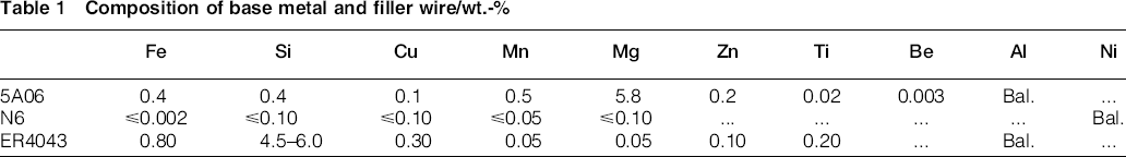
5A06 Al alloy plates with a thickness of 3 mm and commercial N6 pure Ni plates of the same dimensions were used as base materials. The Ni wt-% in the plates was beyond 99.5%. ER4043 (AlSi5) wire was used as filler metal. The chemical compositions of 5A06 alloy, N6 nickel wire and ER4043 filler wire are shown in Table 1. The experimental set-up included a CMT welding system (TPS 4000) and a welding platform. A robot (IRB 1600ID) was used to control the welding torch's movement in an x–y–z coordinate system. Figure 1 shows the schematic diagram of welding process. The angle between the electrode and the normal direction of the workpiece surface was 30°. Before welding, the surfaces of the plates were degreased by acetone, and the oxide films were removed by scratch brushing. A pure CMT process was performed with a 120 A welding current (wire speed: 5.8 m min− 1) and welding velocities of 9, 11, 15 and 17 mm s− 1 respectively. A shield gas of flowing Ar was used as a protective atmosphere in order to prevent the welding materials from being oxidised under high temperature.
Composition of base metal and filler wire/wt.-%
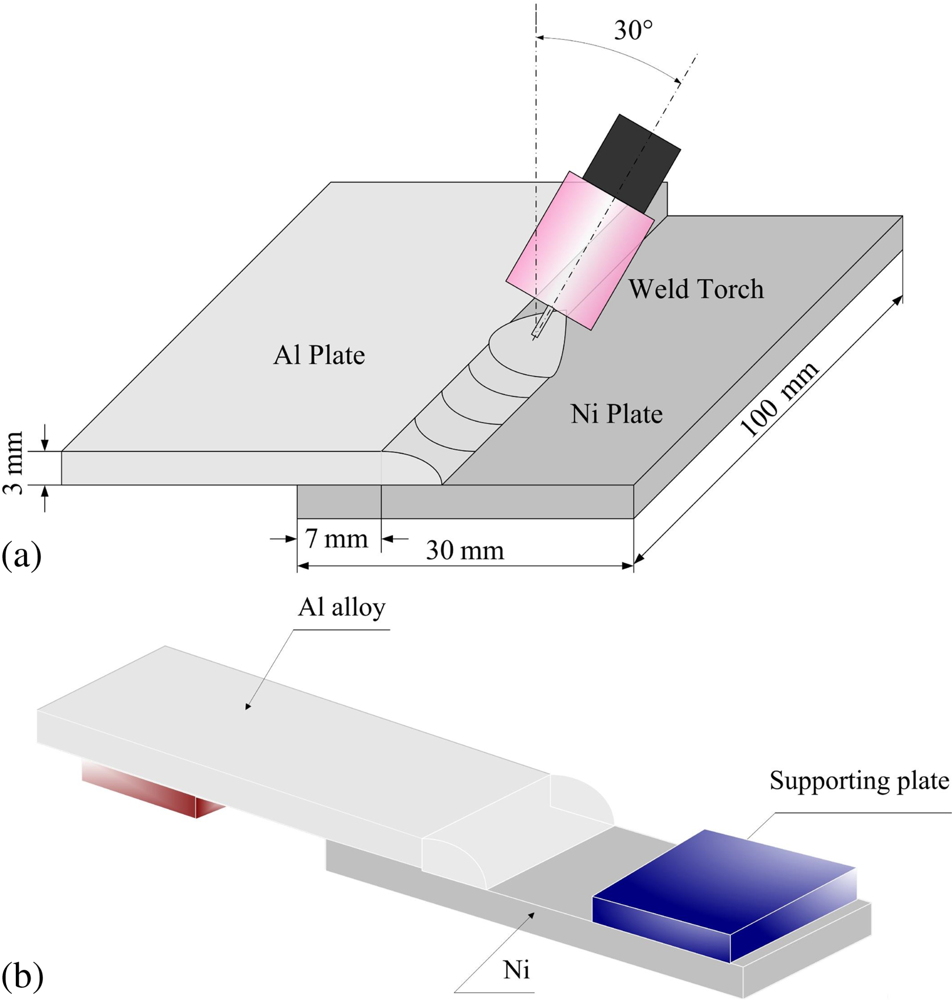
Schematic of lap joint sample (a) and of shear test (b)
After welding, the transversal sections of the lap joint were examined using an S-3400 scanning electron microscope (SEM) in backscattered electron mode, and a LEO Gemini 1530 microscope equipped with an energy dispersive spectrometer (EDS). A JDX-3530M X-ray diffractometer (XRD) was used to identify the metallographic phases in the fracture of the lap joint. XRD testing with Cu Kα radiation was performed at a voltage of 40 kV and an angle incidence of 20–90°. Shear testing was performed with an Instron-1186 mechanical testing machine to evaluate the shear strength of the lap joint at room temperature. The schematic of the shear test is shown in Fig. 1b, which was also adopted in Ref. 23. Shear strength tests were performed at a constant speed of 1 mm min− 1, and average strength was determined using three samples produced under identical conditions.
Results and discussion
Typical microstructural characterisation of aluminium alloy/nickel lap joint
Figure 2a shows the macroscopic appearance of the lap joint. Favourable wettability of the aluminium alloy on the nickel's surface was present without involving any brazing flux or galvanisation treatment, which was normally adopted in Al–steel welding.24, 25 At the interface of the Ni–Al lap joint, different thicknesses of IMCs were found in specified areas. Figure 2b and c shows the enlarged microstructure of zones I and II respectively. The range of the thicker IMC region was 1–1.5 mm in length (zone I). During the welding process, this zone was located under the welding arc and displayed effects of the arc's direct heat. The IMC layer grew thicker than other positions due to this. However, the interface alongside zone I was formed by the molten filler metal spreading to the nickel surface (zone II). Compared to zone I, the reaction temperature of zone II was much lower. As a result, the IMC layer in this area was thinner, with an average thickness of 2 μm. Generally, the IMC thickness contributes significantly to the overall mechanical properties of the joint;26, 27 to this effect, the following research focuses mainly on the microstructure of the thick IMC zone of the interface.
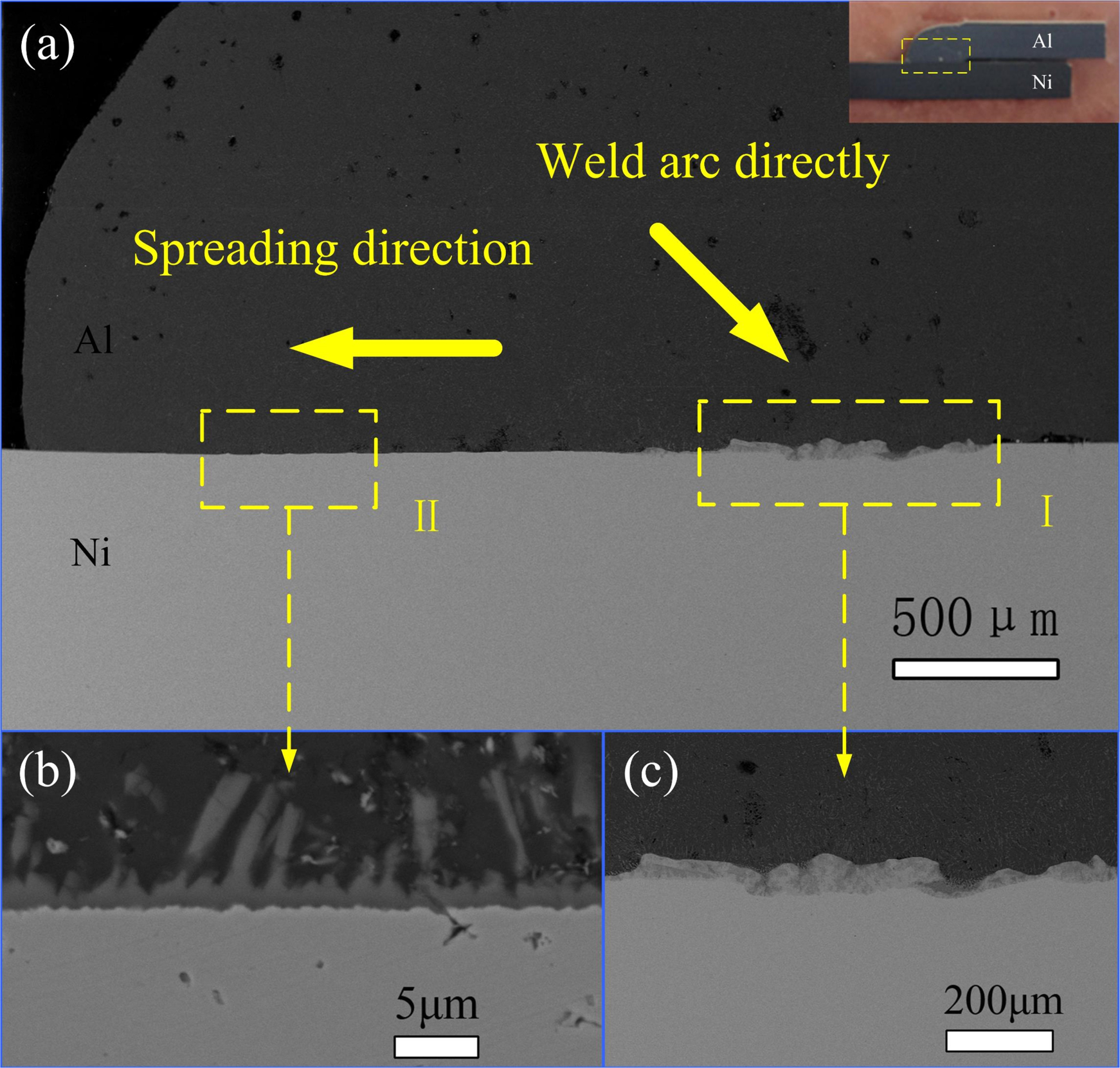
a macroscopic appearance of the lap joint, b magnified image of zone II Fig. 2a, c magnified image of zone I in Fig. 2a
Microstructure of thick IMC zone
Figure 3a shows the microstructure of the aluminium alloy/nickel lap joint welded at 120 A and 17 mm s− 1. As is clearly shown in Fig. 3a, the welded joint was divided into four parts. According to composition analysis in Table 2, the white section in zone I is the nickel base metal with microscale diffused aluminium. Zone II was the reaction zone of Ni/Al, which mainly consisted of the IMC of nickel and aluminium. Zone III was the interfacial zone between the IMC layer and the weld zone, where several micrometer scale columnar NiAl3 structures grew from the interface of zone II. Zone IV was the weld zone, mainly composed of the filler metal, melted aluminium alloy plate and some dissolved nickel elements from the base metal. From the microstructure morphology of IMC layer in zone II, some irregular island-like or flocculent structures were observed due to the heterogeneous distribution of components caused by the high temperature and rapid cooling of the fusion welding process. In addition, the ripple-like boundary on the edge of zones I and II also revealed that the rate of the diffusion reaction of Ni/Al from the reaction zone to the pure Ni side was not uniform. Combined with the EDS results of the characteristic region, the grey phase marked as area B was Ni3Al, and the phase marked area C was Ni0·9Al1·1 or NiAl. The dark grey phase shown in area D was Ni2Al3. The columnar intermetallic phase of area E was stoichiometric NiAl3.
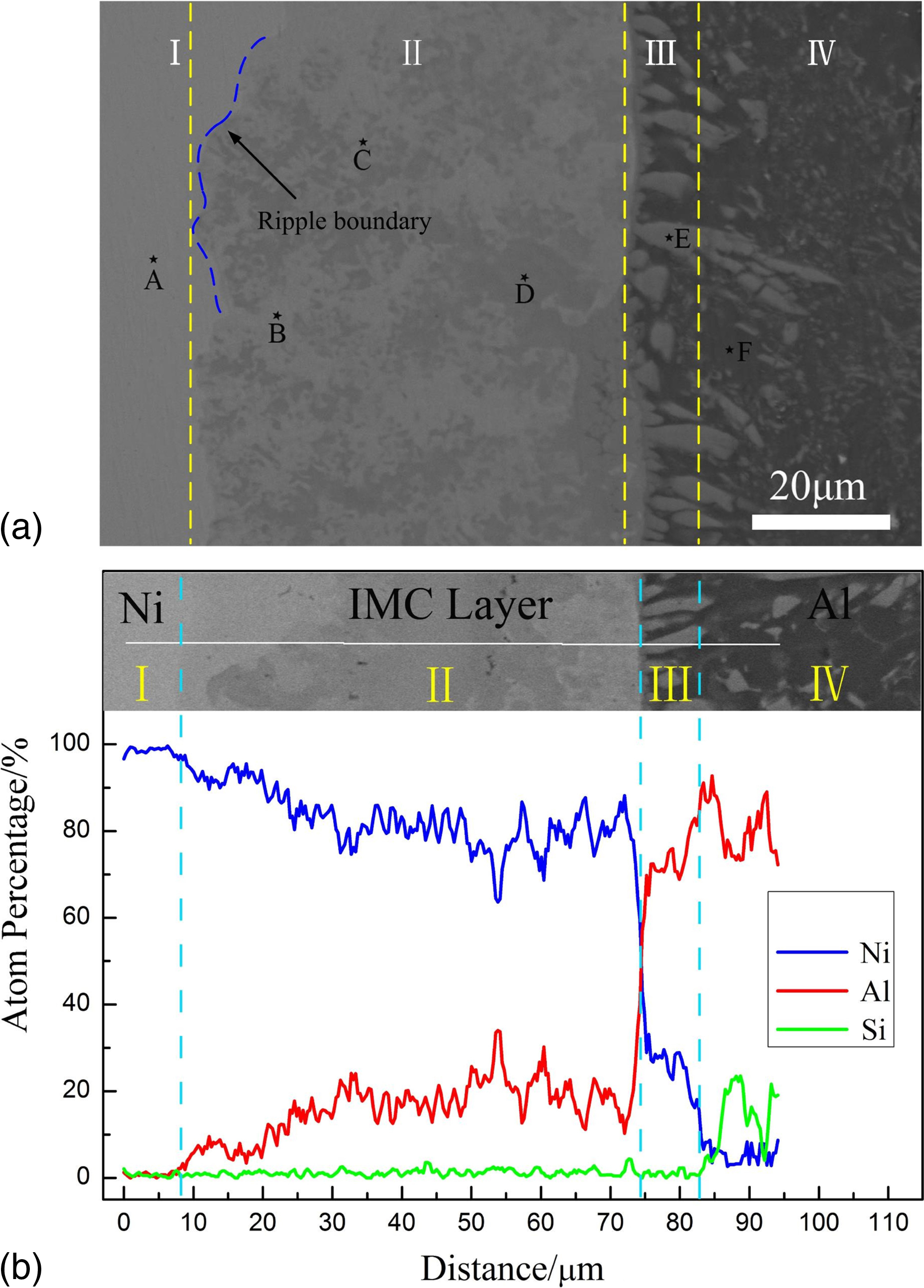
a microstructure of thicker IMC zone welding at 17 mm s-1; b elemental analysis across Ni–Al interface by EDS
Average chemical compositions of each region (at-%) in Fig. 3a
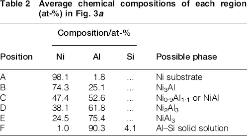
Figure 3b shows the line analysis across the interface of the Ni/Al lap joint by EDS. According to the results in Fig. 3b, the Ni3Al and Ni–Al(s, s) were the main phases in zone II. Lopez et al. 21 investigated the phase characterisation of diffusion soldered Ni/Al/Ni interconnections at 720°C, and revealed that the formation of a thick Ni3Al layer (15 μm) requires a relatively longer holding time (3 h) than that of NiAl3 (5 min) and Ni2Al3 (10 min). However, in our study, under consideration of the rapid cooling rate of the fusion welding process, it was considered unlikely that a Ni3Al and Ni–Al(s, s) layer of at least 60 μm would form through solid diffusion reaction alone. Therefore, the most likely scenario was the generation of a micrometer scale fusion layer at the nickel's surface by the direct heat effect of the welding arc. According to the Ni–Al binary phase diagram, Ni has a wide γ solid solution range with significant solubility of Al up to 21.1 at-% at its eutectic temperature (1658 K), but has a low solid solubility of Al to 0.01 at-% at a low temperature (773 K). 28 Thus, we propose that if the liquid Al at the root of the welding pool mixes with the liquid film of Ni, and the Ni exists in a large solid solution at the initial stages of welding, then with the cooling of the welding pool, Ni3Al and Ni–Al (s, s) will precipitate at the intermix zone by the rapid decrease in solid solubility as well as the thermodynamic driving force of the formation of Ni/Al, ultimately constituting the main part of zone II. As shown in Fig. 3b, a compositional gradient decrease in Ni was also observed between zone II and zone III with a thickness of 2 μm. This consisted of the sequential NiAl and Ni2Al3 phases by their respective compositional gradient. The NiAl3 in zone III showed nucleation through the peritectic reaction of Ni2Al3 and liquid Al, and grew in a direction perpendicular to the Ni/Al interface.
Figure 4 shows the XRD curves measured at both side fractures of the lap joint. It was determined that NiAl3, Ni0·9Al1·1 and Ni3Al existed in the interface of the Ni/Al joint, although these peaks of phase were relatively weak. Ni2Al3 was not observed at the surface of the fracture, possibly attributable to the consumption of Ni2Al3 during the peritectic reaction at zone III. Additionally, Ni–Si IMC was not detected in the XRD analysis, corroborated by linescan analysis. We did not consider the Si element to have effectively inhibited the formation of Ni–Al IMC as it does in Al–Steel welding 29 , because the Si concentration in this case was only 5%.
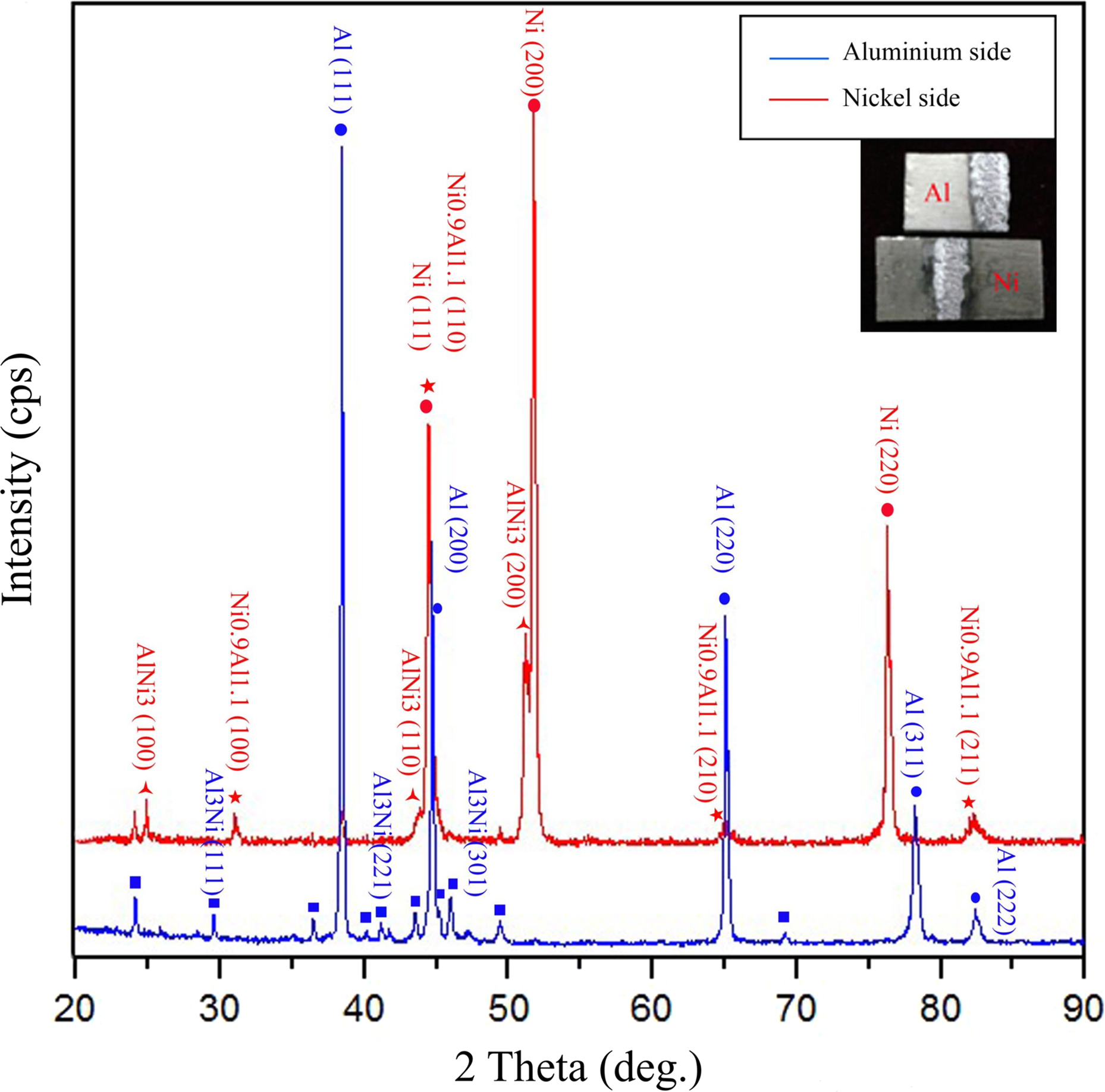
XRD pattern of fracture on both nickel and aluminium sides
Microstructure of thin IMC zone
Figure 5 shows the microstructure of the thin IMC zone in the interface of Ni/Al welded at 9 mm s− 1. Compared to the thick IMC zone, the microstructure in the thin IMC zone was relatively simple. By means of EDS analysis, the IMC layer was found to consist mainly of NiAl3. The relatively low interface temperature and the rapid cooling rate were considered to inhibit the development of sequential Ni2Al3, NiAl and Ni3Al.
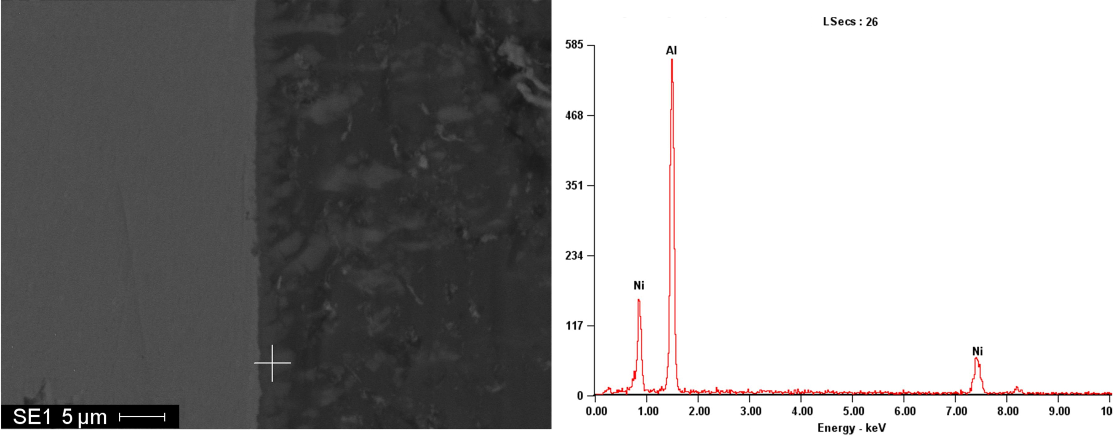
Microstructure and EDS result of thinner IMC zone
Effect of welding velocity on microstructure of aluminium alloy/nickel lap joint
To demonstrate the development of the microstructures at the Ni/Al interface caused by various welding velocities, Fig. 6 shows the SEM images of the thick IMC zone under different welding velocities. It was clearly observed that with an increase in welding velocity, the four zones (I–IV) all emerged in the joint similarly, but the thickness of the intermetallic layer (zone II) and the morphology of the NiAl3 (zone III) grown in the interface showed significant variations. Under a welding velocity of 9 mm s− 1 (Fig. 6a), the thickness of the intermetallic layer averaged 80 μm, the NiAl3 grains at the edge of the intermetallic layer were 5 μm, and several microcracks were found in the interface, as shown in the magnified image. At the root of the weld, a large amount of blocky, striated NiAl3 were embedded in the Al alloy matrix due to increments of Ni dissolved into the weld by increased heat input. With an increase in the welding velocity (Fig. 6b and c), the intermetallic layer gradually thinned. At a velocity of 15 mm s− 1, the thickness of the intermetallic layer decreased to 40 μm. Compared to the NiAl3 morphology features when welded at a low velocity, the interface structure in Fig. 6c was more compact, and the columnar NiAl3 bonded better to the bottom IMC layer (shown in the enlarged SEM image of Fig. 6c). However, with a further increase in the welding velocity (in Fig. 6d), the intermetallic layer thickened again. The maximum thickness reached 100 μm, where the NiAl3 interface became thin and slim.
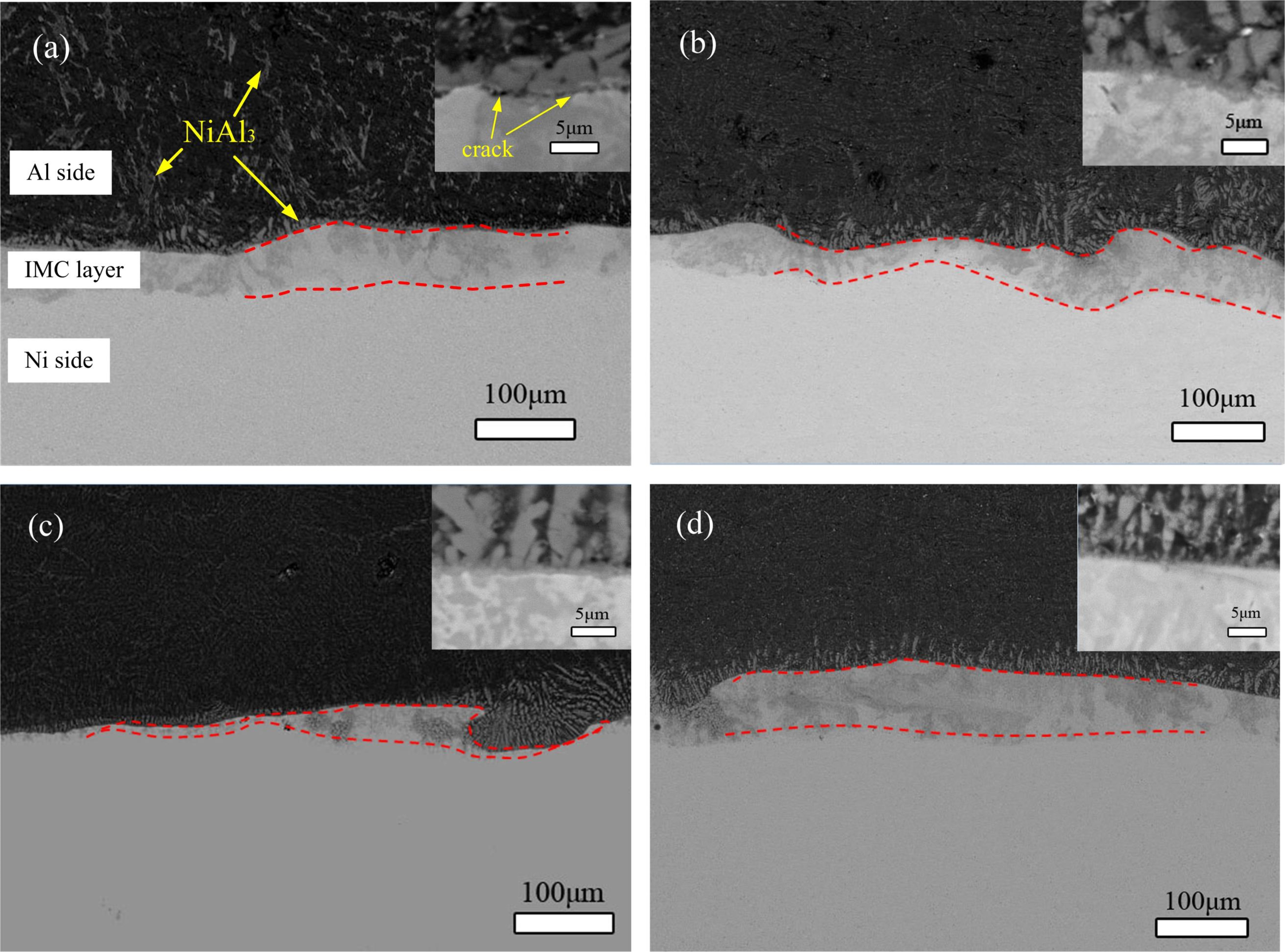
a 9mm s-1, b 11 mm s-1, c 15mm s-1, d 17mm s-1
Mechanical properties
The shear strength of the lap joint at different welding velocities is shown in Fig. 7. By looking at the column pattern, a positive correlation was found between strength and microstructure. The maximum shear strength of 42 MPa was obtained at the joint with the thinnest IMC layer (shown in Fig. 6c), and the strength decreased as the IMC layer became thicker. When the welding velocity was 9 mm s− 1, longer molten retention time promoted the diffusion of the nickel and aluminium, and as a result, the IMC layer grew thicker. High heat input was also able to increase the thermal stress at the interface of Ni/Al, which trigged microcracks in the interface. Under the action of shear force, these cracks become a weak link in the interface and reduce overall shear strength. With an increase in the welding velocity, the diffusion of nickel to weld reduced, the IMC layer became thinner, and the diffused nickel was mainly captured by aluminium at the Ni/Al interface, forming the NiAl3, which grew into the weld. Therefore, both a reduction in thickness in the brittle IMC layer and compact interface structure contributed to enhancement of the joint's strength. However, with a further increase in velocity, the shear strength of the joint decreased in the thicker IMC layer. As previously noted in Fig. 2, the thickness of the IMC layer was not only determined by the internal heat input but also by the maximum temperature at the reaction interface. When the welding velocity exceeds a certain value, the welding arc will supersede the fusion pool and directly impact the nickel surface, rather than the fusion pool. Since the heat of a high temperature welding arc is much greater than the heat conduction of a fusion pool to a metal surface, the temperature of the Ni/Al interface in this case is higher, ultimately promoting the reaction of Ni/Al. Simultaneously, due to the high cooling rate of the fusion pool by the higher welding velocity, the retention time of high temperature at the interface was very brief. This restrains the development of NiAl3 and weakens the bond between NiAl3 and the IMC layer, which leads to the low strength of the lap joint.
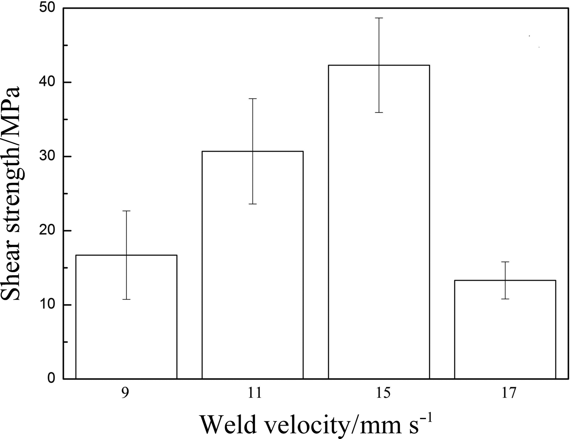
Effect of welding velocity on shear strength of Al–Ni joint
Fracture morphology
The SEM image displayed in Fig. 8 shows the fracture morphology of the Ni–Al lap joint. A rupture occurred at the IMC layer, which illustrated the brittle fracture characteristics of the material. The elemental compositions at the marked zone were collected to identify possible phases in the fracture's surface. From the results in Figs. 4 and 8, it was indicated that the smooth surface in zone A was NiAl, and the ridge-like zone mainly consisted of NiAl3. Under the action of shear force, a crack formed in the IMC layer. With the further increase in the load, the microcracks formed mainly through the NiAl lattice plane, but also through the root of the NiAl3 layer, ultimately leading to the joint's fracture.
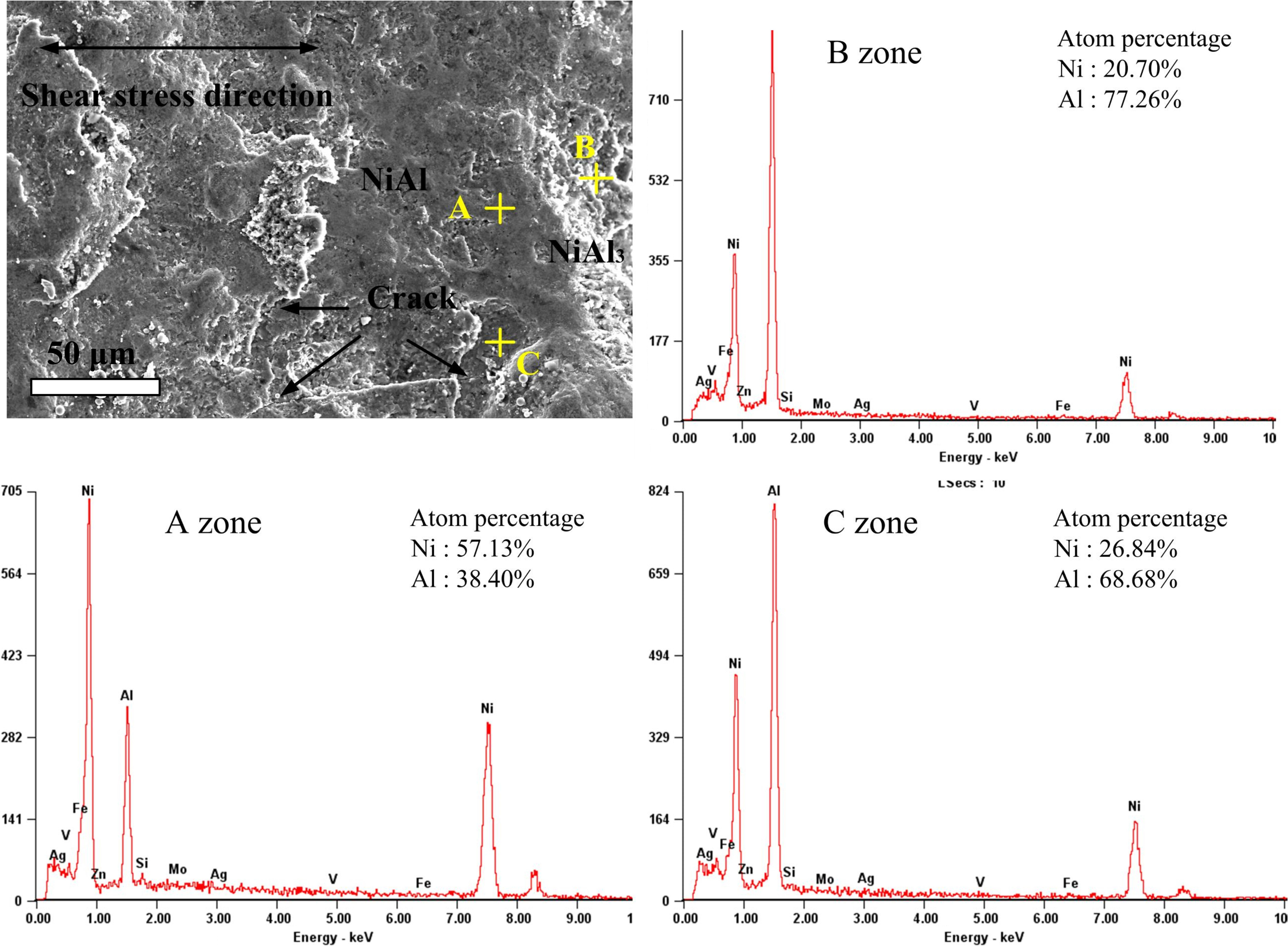
Fracture morphology and chemical composition of Ni-Al lap joint welded at 17 mm s-1
Conclusions
5A06 Al alloy was successfully welded to pure Ni using a filler metal of ER4043 wire. Based on the results obtained in this work, the following conclusions are drawn.
The typical microstructure of the Al/Ni joint was divided into four parts: the nickel base metal; Ni3Al, Ni0·9Al1·1 and Ni2Al3 IMC layer; columnar NiAl3 layer; and Al–Si solid solution weld, as formed sequentially from the nickel side to the aluminium side.
The reaction between Ni and Al was sensitive to the interface temperature. With an increase in welding velocity, the thickness of the IMC layer was first decreased and then grew. At a velocity of 15 mm s− 1, the minimum thickness layer of 40 μm with a compact interface was obtained.
The greatest shear strength, 42 MPa, was obtained at a welding velocity of 15 mm s− 1. The joint strength continued to decrease as the IMC layer thickened. The fractures were mainly located in the NiAl and NiAl3 IMC layer.
Acknowledgements
This project is supported by the National Natural Science Foundation of China (grant nos. 51475104 and 51435004).