
Abstract
Friction stir welding (FSW) is a solid state welding process used to weld difficult to be welded or unweldable materials as aluminium alloys. In the last years, other materials have been successfully tested as magnesium, titanium and nickel based alloys. Dissimilar joints can be obtained by FSW, but issues arise concerning the correct choice of the process parameters. In the paper, the results of an experimental and numerical campaign aimed to produce dissimilar AZ31-AA6016-T6 butt joints are presented. The effect of sheet mutual position and main process parameters was investigated. It was found that intermetallics are the main cause of the poor quality of the joints. Sound joints can be produced only if the magnesium alloy is in the advancing side.
Introduction
Friction stir welding (FSW) is a solid state welding process patented and developed by The Welding Institute (TWI) in 1991 in which a rotating tool with a pin at its end is plunged, with a proper tilt angle, between two blanks to be welded and moved all along the welding line. Material solid bonding is obtained because of the tool stirring action softening the material and generating a complex plastic flow.
FSW was first developed to obtain sound joints out of aluminium alloys previously considered non-weldable. 1 It was then successfully applied to other materials such as titanium and magnesium alloys. In particular, as Mg alloys are regarded, Rajakumar et al. 2 carried out a comparative study between friction stir and pulsed current gas metal arc welding, finding out that FSWed joints are characterised by larger tensile and yield strength values. Padmanaban and Balasubramanian 3 observed excellent fatigue properties of the welds, only slightly lower than the base material.
As a solid state process, FSW is particularly suited for the production of dissimilar joints between different materials, as different aluminium alloys4, 5 or aluminium alloys to titanium alloys6, 7 and steels. 8 In the last years, one of the most interesting research fields for the transportation industry has been the feasibility of dissimilar Al–Mg welded joints. The use of dissimilar Al–Mg joints in industrial application provides a number of advantages, 9 among which weight reduction and improvement of the design flexibility. 10 It is worth noticing that dissimilar Al–Mg structures can be obtained using conventional welding technologies. However, the process is extremely expensive and ineffective, and it is currently used only for products characterised by high added value. Additionally, handmade welding and several quality controls are required. 1
The use of solid state welding can allow process quality improvement, making it suitable for large scale production. Nevertheless, the literature is currently characterised by a lack of knowledge about FSW of dissimilar Al–Mg joints, as few efforts to study the process were often contradictory. Some authors affirm that the Mg alloy can be placed in the advancing side joint in order to produce sound welds. Malarvizhi and Balasubramanian 11 obtained high joint efficiency using this material positioning. Sato et al. 12 analysed constitutional liquidation phenomena in the weld centre of dissimilar Al–Mg FSWed joints, welded with aluminium in the RS. On the contrary, Simoncini and Forcellese 13 draw opposite conclusions. None of the cited authors investigated the influence of sheet mutual position on the quality of the welds. Malarvizhi and Balasubramanian 11 carried out an experimental campaign to identify the optimal ratio between shoulder diameter and plate thickness, finding that the heat flux required to obtain sound welds in Al to Mg FSWed joints is marginally higher than in similar welding. Yan et al. 14 analysed the effect of tool offset on the joints quality, noticing that the null offset configuration causes a massive formation of eutectic compounds that affect the welding strength. Although eutectic formation has been noticed by many authors,12, 14–17 their mechanism of formation remains unclear. Sato et al. 12 suggest that intensive diffusion phenomena could ‘form a liquid phase constitutionally when the material is constantly held at temperatures higher than 733 K’. This theory is supported by previous studies on inertia friction welding in which Yashan et al. 18 state that the solid state diffusion is enhanced by high strain rate plastic deformation typical also of the FSW process. On the other hand, Kwon et al. 19 did not observe any eutectic or intermetallic formation and claim that the kinetic parameter does not affect the mechanical strength of defect free joints.
In this paper, an experimental and numerical investigation on hybrid butt joints of AA6016-T6 to AZ31B is presented. In particular, the joint strength and the metallurgical and chemical properties are investigated with varying mutual position (advancing or retreating side), tool rotation and feedrate. Obtained results demonstrate that the analysed alloys are weldable, allowing good joint efficiency compared to the lower strength base metal, only if proper sheet mutual position is used.
Experimental
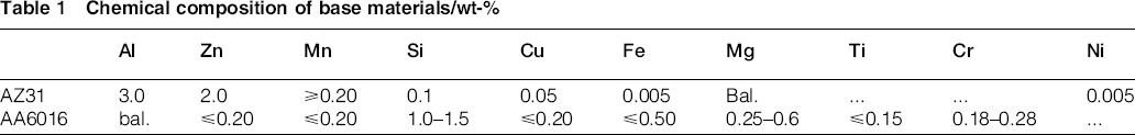
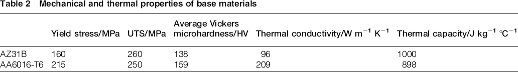
Butt joints were obtained out of 100 mm × 80 mm metal sheets, 2 mm in thickness. The chemical composition and the mechanical properties of the base materials are presented in Tables 1 and 2 respectively.
Chemical composition of base materials/wt-%
Mechanical and thermal properties of base materials
The tool was made of high speed steel with a plane shoulder, 10 mm in diameter, and a tapered pin, 1.6 mm in height. The pin base diameter was 3.4 mm with an angle of 30°. The experiments were performed on a computer numerical controlled milling centre. Twelve different case studies were analysed with varying tool rotation, feedrate and mutual position of the sheets. In particular, two different values were chosen for tool rotation (R) and three valued for the feedrate (V): 1000 and 1500 rev min− 1 and 50, 100 and 150 mm min− 1 respectively. In the following, each case study will be indicated by the alloy in the AS, and the R and V values are used (e.g. Al-1000-50). All the welds were performed with constant tilt angle equal to 2°, constant plunging depth of the shoulder trailing edge (TE) in the sheets equal to 0.2 mm, constant plunging speed and constant null offset. Each experiment was repeated three times, and three specimens were saw cut from the central area of each joint, orthogonally to the welding direction, for successive analysis. Tensile tests were performed on a 5 tons material testing machine, with constant crosshead speed of 1 mm min− 1. The specimens had constant width equal to 15 mm.
The specimens were hot mounted and polished according to ASTM E407-09 standard and constantly doused with ethanol to avoid water contamination as suggested by several authors.11, 13 The specimens hence underwent a double acid etching to highlight the microstructure of the two metals and intermetallics. The samples were first pre-etched for 5 s in a 5% (w/w) aqueous solution of NaOH and then plunged in a 5% (w/w) ethanol solution of HNO3. Any intermetallic compound would be pointed out by this pre-etch. The Mg side of the sample was then etched for 12 s by a picric reagent composed of 1 mL of picral 4 [4% (w/w) ethanol solution of picric acid], 1 mL of distilled water and 7 mL of glacial acetic acid. In turn, the Al side was dipped for 90 s in a Keller reagent. The microstructure was then observed by an optical microscope, and the grain size was measured according to ASTM E112-13. Microhardness in the weld transverse section was measured using a 500 g load along one measurement line 1 mm from the bottom of the sheets, i.e. at the joint mid height.
Some of the authors of the present paper have developed a ‘single block’ based numerical model for the prediction of the main field variables in FSW. 20 The model has been fine tuned and validated for 6XXX and 7XXX aluminium alloys1, 21 as well as AZ31 magnesium alloy.22, 23 Additionally, a specific procedure has been developed in order to simulate the FSW of dissimilar materials. 24 In particular, in Ref. 20, details on the governing equations and the boundary conditions used for the model set-up can be found, while in Ref. 24, the procedure used to take into account the presence of two different materials in the same joint is discussed. Buffa has recently used the model to highlight the main field variable distributions and the occurring material flow in FSW of dissimilar Al/Mg butt joints. 25 In this study, the developed model has been used to highlight temperature, strain and material flow occurring during the process. All the considered case studies were simulated.
Finally, EDX (energy dispersive X-ray spectroscopy) analysis was carried out using a scanning electron microscope in order to highlight the chemical composition along the cross-section of the joints.
Results and discussion
Mechanical characterisation
First, the mechanical properties of the obtained joints were tested. Figure 1 shows the Mg-1500-50 and the Al-1500-50 case studies. A more regular weld seam is obtained when the magnesium alloy is in the AS. In turn, an irregular seam, characterised by increased flash at the sides, is obtained when AA6016 is in the AS. Additionally, an irregular fracture line is observed, indicating that unstable welding conditions are established during the welding process.
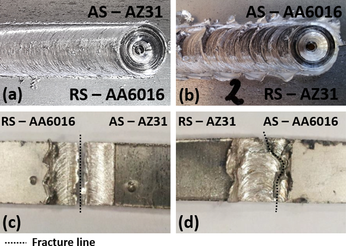
Weld seam for a Mg-1500-50 and b Al-1500-50 and tensile specimen after failure for c Mg-1500-50 and d Al-1500-50
Figure 2a shows the average values of the ultimate tensile strength (UTS) of the joints as the percentage of the UTS value of the softer material at room temperature, i.e. AZ31. The same nomenclature used in the rest of the paper was utilised for this figure, e.g. Al-1000 indicates the set of welds produced placing the aluminium alloy in the AS and tool rotation R equal to 1000 rev min− 1. In Fig. 2b, the load versus the displacement curves of the tensile tests for the two parent materials (PMs), the Al-1500-50 and the Mg-1500-50 case studies, are reported. All the welds showed a significantly reduced plastic field with respect to the PM. In this way, similar yield stress and ultimate tensile stress are obtained. It should be observed that this behaviour is consistent with the one found by Simoncini and Forcellese 13 for dissimilar AA5754 and AZ31 friction stir welded joints. Focusing on the welds obtained placing the magnesium alloy on the AS, increasing UTS is obtained with increasing heat input. In particular, the UTS value ranges between 62%, considering the ‘coldest’ welding condition, i.e. Mg-1000-150, and 76%, considering the ‘hottest’ weld, i.e. Mg-1500-50. However, the relative small value in UTS, compared to the range of values used for V (50–150 mm min− 1, corresponding to an increase of 300% with respect to the lower value) and R (1000–1500 rev min− 1, corresponding to an increase of 50% with respect to the lower value), indicates that robust process conditions are obtained. On the other hand, placing the aluminium alloy on the AS results in lower performances; as for most of the case studies, UTS drops by >50%.
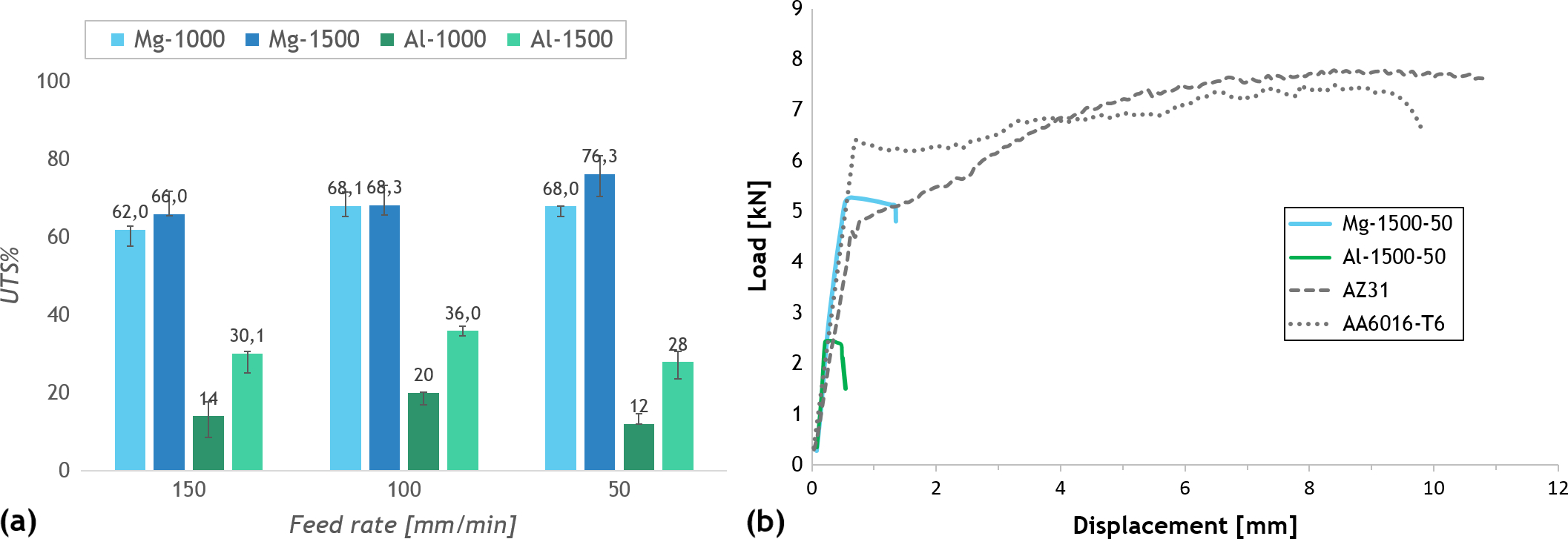
Tensile tests results for analysed case studies: a average joint efficiency and b load versus displacement curves for base materials and Mg-1500-50 and Al-1500-50 case studies
Microhardness was measured in a transverse section of the joint at mid-height. In Fig. 3, the obtained distributions are shown for Mg-1000-150, Mg-1500-50 and Al-1500-50 joints corresponding to the lower and higher values of heat input respectively and, for the latter conditions, to the changed mutual positions of the sheets.
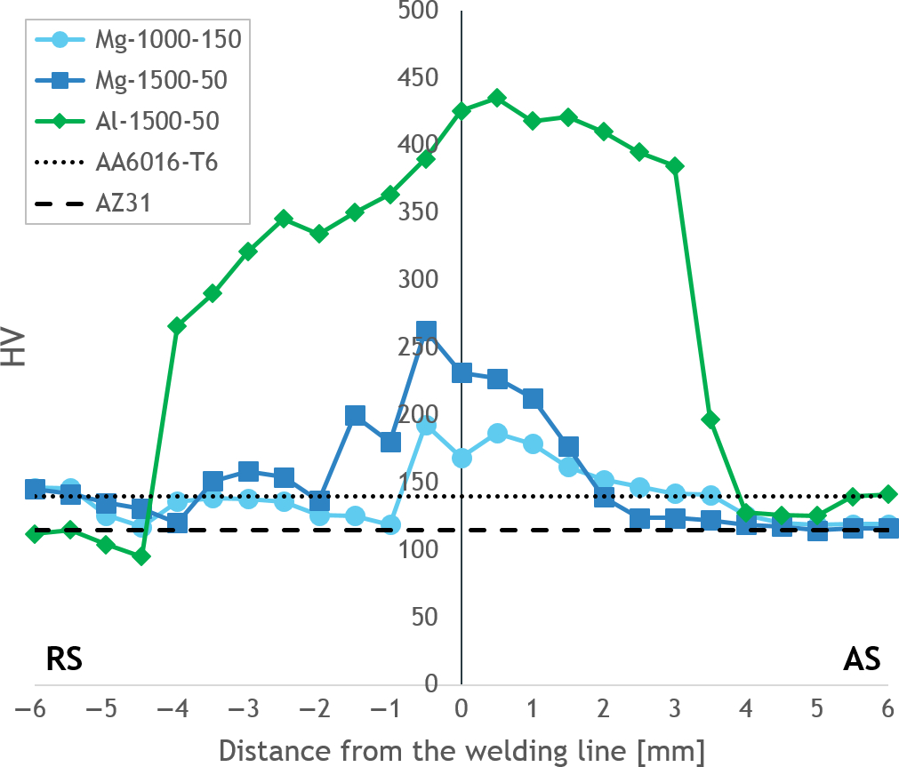
Microhardness profiles in transverse section for Mg-1000-150, Mg-1500-50 and Al-1500-50 case studies
For the three welds, an increase in the HV in the weld nugget with respect to the PM is noted. It is worth noticing that in FSW of similar AA6016 sheets, a decrease in HV is observed in the weld nugget due to the dissolution of precipitates induced by the thermal cycle the material undergoes during the process. 26 As it will be better explained in the following, the formation of intermetallics can lead to microhardness increase. As expected, similar values are measured for the two joints obtained with the same sheet position, i.e. with the AZ31 on the AS. In particular, consistently with the tensile test results, slightly larger values are obtained for the welding conditions characterised by higher heat input. On the other hand, significantly larger values are found in the weld obtained with AA6016 on the AS. These HV values lead to an extremely fragile behaviour of the joint, resulting in the poor performance observed during the tensile tests.
Metallurgical characterisation
The cross-section of the joints was analysed through macrographs in order to qualitatively study the materials mixing in the nugget, optical micrographs, highlighting grain size and shape, and EDX analyses, in order to point out the presence of intermetallics.
First, the macrographs of the same joints analysed in Fig. 3 are presented in Fig. 4a. As it can be observed from the figure, the two different materials can be clearly identified in the joint cross-section. When the Mg alloy is placed in the AS, it is shifted beyond the welding line, namely, in the RS of the joints. On the other hand, when the Al alloy is initially placed in the AS, the AZ31 in the RS is shifted towards the AS and a large ‘hybrid’ zone is visible in the nugget area, indicating that different material flow conditions are established.
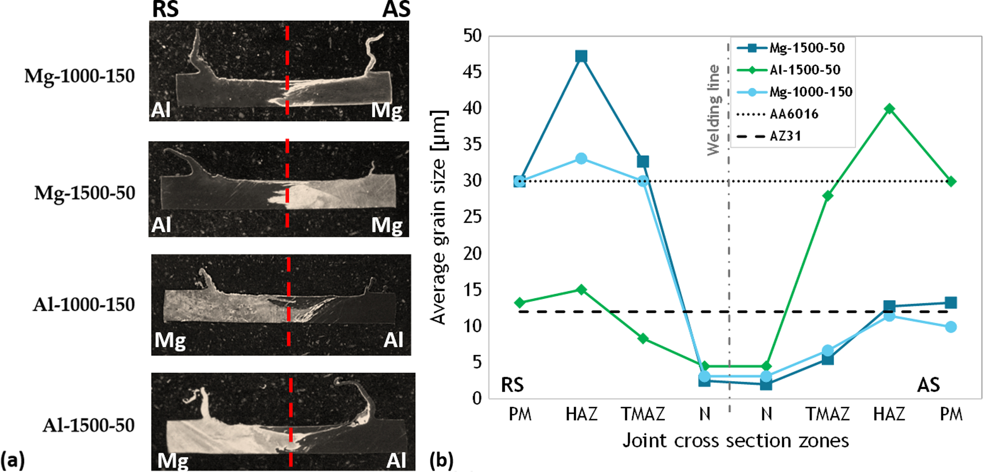
a macrographs of etched transverse section for Mg-1000-150, Mg-1500-50, Al-1000-150 and Al-1500-50 case studies; b average grain size for Mg-1000-150, Mg-1500-50 and Al-1500-50 case studies
The average grain size was measured for each carried out test. Figures 5 and 6 show the micrographs of the typical areas of the Mg-1000-150 case study, namely, PM, heat affected zone (HAZ), thermomechanically affected zone (TMAZ) and nugget. A larger grain size of the base material for the aluminium alloy is observed. Additionally, in the TMAZ, AA6016 is characterised by an elongated shape with relatively large grains. In turn, in the same area, the AZ31 shows that the continuous dynamic recrystallisation (CDRX) process has already partially taken place, resulting in large areas characterised by small equiaxed grains.
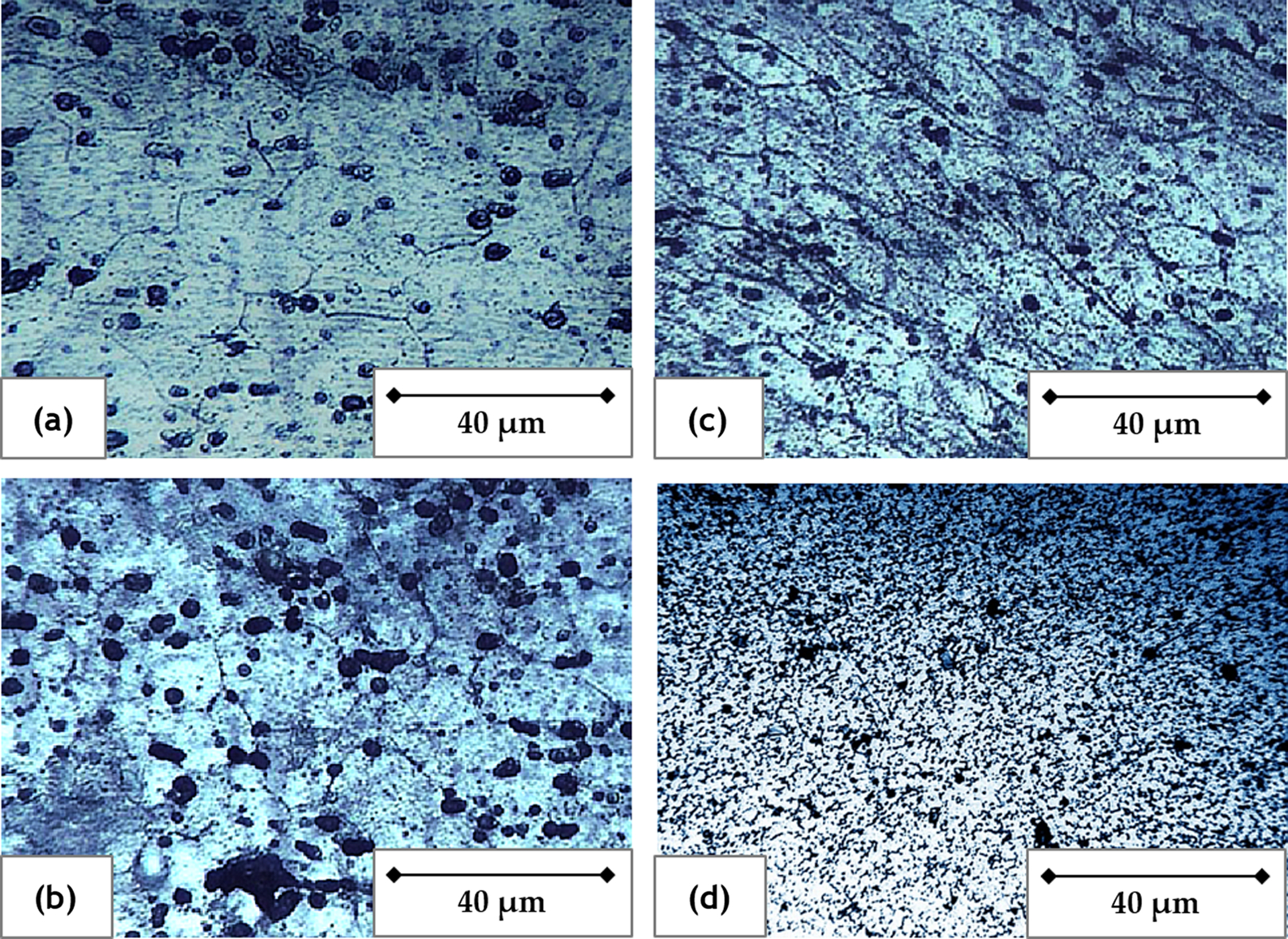
a PM; b HAZ; c TMAZ; d nugget
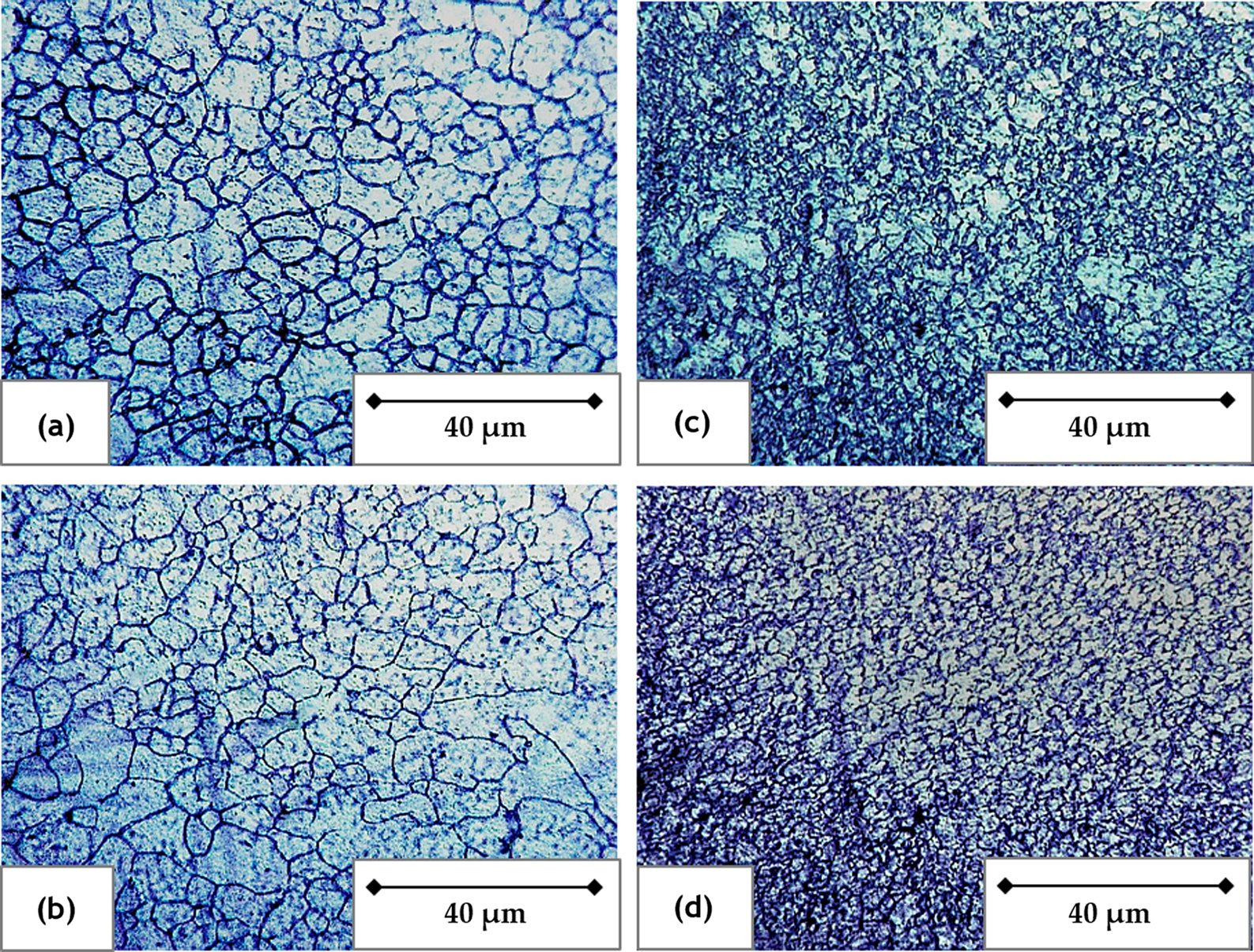
a PM; b HAZ; c TMAZ; d nugget
An increase in the average grain size with respect to the PM is observed in the HAZ and TMAZ in the aluminium alloy side, and slightly larger grains are found for the hottest weld with respect to the coldest one (see Fig. 4b). However, this does not have detrimental effects on the joint mechanical strength. A dramatic reduction in the grain size is found in the nugget due to the CDRX phenomena. In turn, no significant grain growth is found in the HAZ of the magnesium side due to both the reduced temperature, as it will be better explained in the next paragraph, and the lower sensitivity to grain growth of the considered alloy with respect to aluminium. Similar values are found in the weld nugget for the two materials with varying process parameters. Finally, looking at the configuration with Al in the AS, a specular profile is found, indicating that metallurgical phenomena related to temperature cycle are not influenced by the sheet mutual position.
Finally, the results of the EDX analysis on the Al-1500-50 and Mg-1500-50 case studies are shown in Fig. 7. In particular, the weight permille of Al and Mg measured along the red line highlighted in the figure is reported. It is worth noticing that this choice permits to effectively identify the presence of the two considered alloys, as AA6016 has only a small percentage of Mg (Table 1).
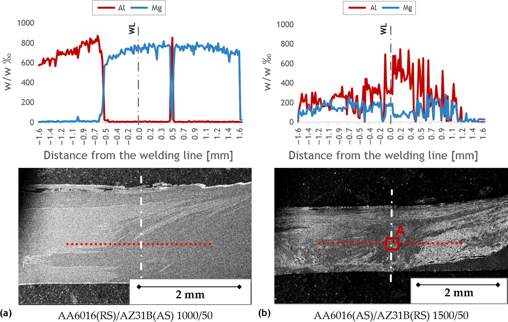
Al and Mg weight permille for Mg-1500-50 and Al-1500-50 case studies
Two completely different profiles are obtained. When AZ31 is on the AS, a well defined separation is observed between the two alloys. Only a small Al inclusion is found in the AS. On the other hand, a wide, completely mixed zone is observed when AA6016 is on the AS, with variable percentage of Al and Mg all along the measuring line. In order to better investigate the nature of this area, local EDX analyses have been carried out. Figure 8 shows the result found in the nugget area (see point A in Fig. 7b) of the Al-1500-50 specimen. In Fig. 8a, the EDX revealed a ratio between Al and Mg, indicating the formation of Al3Mg2 intermetallics (β phase in the Al–Mg phase diagram). Figure 8b shows a 6000 × magnification of this area. Microcracks due to the formation of brittle intermetallics are visible on the right side of the micrograph. Other areas of the nugget also showed results consistent with the presence of Al12Mg17 (γ phase in the Al–Mg phase diagram). It is worth noticing that a thin layer of intermetallics is observed also along the material separation surface in the joints obtained with AZ31 placed on the AS.
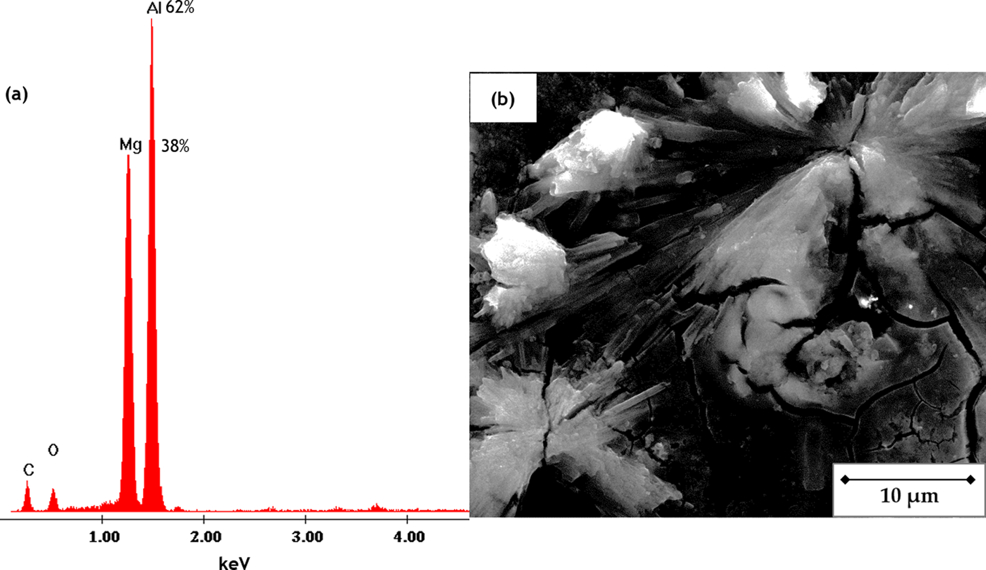
EDX analysis (a) and 6000 × magnification micrograph (b) of Al-1500-50 joint nugget (point A of Figure 7)
Numerical results
The results obtained in this research indicate that good mechanical properties can be reached in FSW of dissimilar aluminium–magnesium joint if proper process parameters are selected. The key process parameter resulted to be the sheet mutual position, as sound joints can be produced only when the magnesium alloy is placed in the AS of the joint.
Both the microhardness analyses and the macrographs of the etched transverse sections of the joints suggest that large ‘hybrid’ areas formed by intermetallics are obtained in the weld nugget when the aluminium alloy is placed in the AS. These compounds are responsible for significant increase in the local hardness values and for a fragile behaviour of the joints, resulting in poor UTS.
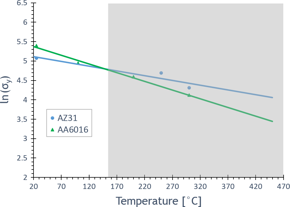
The main effect of the sheet mutual position is the influence on the material flow during the weld. Watanabe et al. 27 carried out FSW experiments to produce dissimilar steel to aluminium joints. They demonstrated that the strongest material has to be placed in the AS of the joints. As far as the materials taken into account in this research are considered, at room temperature, AA6016 is characterised by the largest flow stress. However, material flow is governed by the flow stress of the materials to be welded in the welding conditions, namely, at the process temperature. In Fig. 9, the flow stress, as a function of temperature, is reported for the two materials used in this research.28, 29
Flow stress versus temperature for two materials considered in this research
The temperature distributions, calculated by the field emission microscopy model, show that during the welding process, the temperature in the welding zone is well above 150°C and AZ31 has the largest flow stress with respect to the two considered aluminium alloy. In order to explain the formation of a larger intermetallic area when the Al occupies the AS, further considerations have to be made. First, Sato et al. 12 highlighted that in FSW of dissimilar Al/Mg joints, the formation of intermetallics can be caused by either constitutional liquation or solid diffusion. In the former, the liquefaction and subsequent solidification of eutectics Al3Mg2 and Al12Mg17 occur at temperatures ∼200°C below the melting temperature of the two PMs, i.e. at ∼450°C. Figure 10 shows the temperature distribution, in a top view of the joint, for both the sheet mutual positions (Al-1500-50 and Mg-1500-50 case studies).
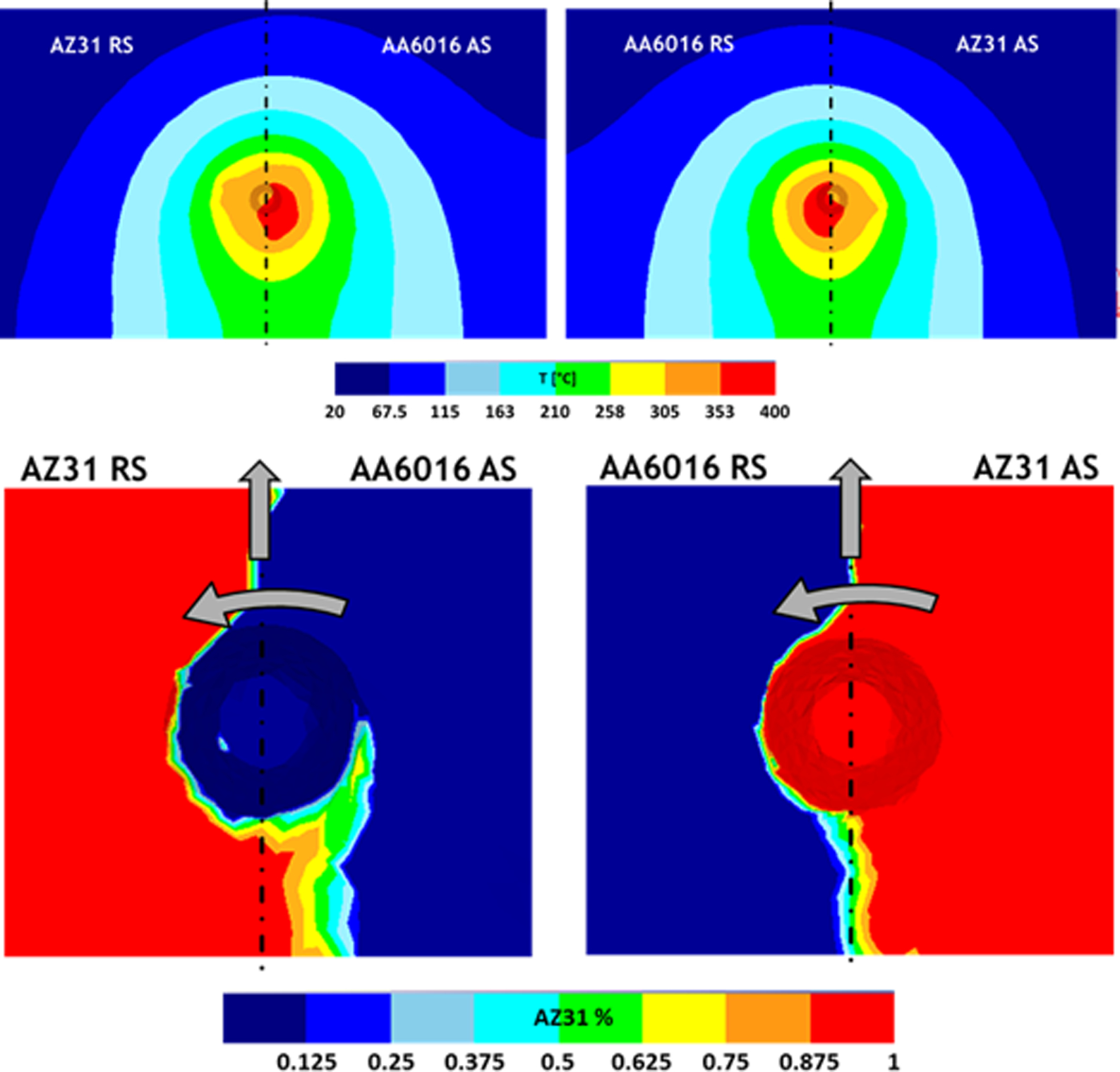
Top view of temperature distribution and material flow for Al-1500-50 and Mg-1500-50 case studies
For all the tests, larger temperatures are measured in the aluminium sheets, regardless of the sheet position with respect to the joint side, i.e. advancing or retreating side. This can be explained looking at the smaller heat capacity and larger thermal conductivity of aluminium with respect to magnesium. It is known that in FSW, most of the heat is generated at the interface between the sheets and the shoulder, and, differently from the strain and strain rate distribution, temperature distribution is symmetric with respect to the welding line. Hence, the same heat is input into both the magnesium and the aluminium sheet and the thermal properties of the two alloys are responsible for the different temperature values observed. As far as the reverse configuration is regarded, no significant difference is observed, being the aluminium side hotter than the magnesium one. Maximum temperature is ∼400°C, which is below the threshold value needed for constitutional liquation to occur. It is worth noticing that the combination of tool rotation and feedrate reported in Fig. 10 corresponds to the maximum heat input in this study. Hence, diffusion bonding is likely to be the phenomenon governing the formation of intermetallics for the joints considered in this research.
Looking at the material flow, temperature predictions show that the leading edge (LE), i.e. the side of the joint ahead of the welding tool, is colder than the TE, i.e. the side of the joint behind the tool. If the softer material is in the AS, it comes into contact with the stronger material in the LE, in which the material has not been sufficiently softened by the heat input given by the tool. In turn, if the softer material is in the RS, it contacts the stronger material in the TE, in which maximum softening is reached. During the process, the material around the welding line rotates with the tool before being left in the TE of the joint. 30 In this area, a significant difference is found between the two case studies. When the AZ31 is in the RS, its final position is beyond the welding line in the AS of the joint. On the contrary, when AA6016 is in the RS, the bonding line is closer to the welding line (Fig. 10). This is due to the stronger mechanical action that the harder material, i.e. AZ31, exerts on the softer one, i.e. AA6016, in the TE. In other words, AZ31 can push the softer AA6016 for a longer distance. As a consequence, an increase in the area involved by large deformation is found when the Al is in the AS (Fig. 11). In this way, the occurrence of solid diffusion (enhanced by strain 12 ) resulting in the larger area characterised by the presence of intermetallics found in the configurations for which the aluminium alloy is in the AS can be correlated to the larger area with high strain and to the material flow influenced by the mutual position of the sheets.
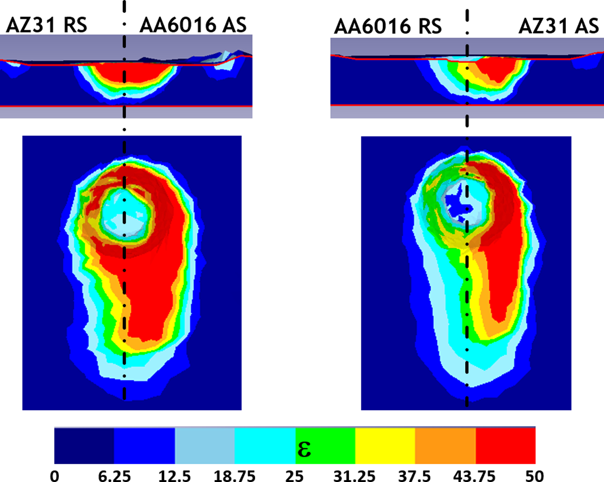
Top view and cross-section of strain distribution for Al-1500-50 and Mg-1500-50 case studies
Summary
In the paper, the results of an experimental and numerical campaign, aimed to investigate the effects of the main process parameters in FSW of dissimilar aluminium–magnesium joints, are presented. AA6016-T6 was butt joined to AZ31B with varying tool rotation, feedrate and sheet mutual position. Based on the obtained results, the following conclusions can be drawn:
Heat input influences the mechanical performances of the joints. Larger UTS values are obtained with increasing heat input.
The sheet mutual position has a dramatic influence on the joint quality. Sound joints could be obtained only if AZ31 is placed in the AS of the joint.
Microhardness tests, micro-observations and EDX analyses highlighted the presence of β and γ intermetallics that weaken the joints. The area characterised by the presence of intermetallics dramatically increases when the aluminium alloy is placed in the AS.
FSW of different materials has been demonstrated more effective when the softer material is placed in the RS. Although at room temperature AA6016 has a larger flow stress with respect to AZ31, the opposite holds true above 150°C, i.e. at the process temperatures.
The results obtained from the numerical model highlighted that, even when the maximum heat input used in this research is conferred to the joint, temperatures in the nugget do not exceed the threshold temperature needed for constitutional liquation. In addition, the contact between the harder magnesium alloy and the softer aluminium alloys in the LE of the joint results in increased strain, which, in turn, enhances the formation of intermetallics by solid diffusion phenomena.