
Abstract
Cold metal transfer (CMT) welding is a promising process to improve the mechanical characteristics of the hard to weld 7075-T6 aluminium alloy owing to its unique advantages in contrast to conventional metal inert gas welding process. The welded joints, using ER5356, were identified and characterised by means of optical microscopy, scanning electron microscopy and energy dispersive spectroscopy. Mechanical properties were measured by tensile and hardness tests. Results indicate that CMT provides better joint tensile strength and ductility compared to metal inert gas welding. The softness in the heat affected zone was very low, but a big hardness gap was recognised in the welded metal compared to base metal. The joint had mechanical property coefficients of 77%, 60% and 69% for yield strength, ultimate tensile strength and elongation respectively.
Introduction
The application of aluminium alloys is increasing in all industrial fields due to its combination of properties such as the low density, good mechanical resistance and good corrosion resistance. 1 The improved mechanical characteristics of the heat treatable aluminium alloys, compared to non-heat treatable aluminium alloys, are the driving force to integrate these alloys in different application fields. Nevertheless, due to the limited weldability of high strength alloys aluminium alloy, it is not always possible to replace non-heat treatable by heat treatable aluminium alloys.
During the welding of these alloys, the precipitation strengthening phases are dissolved in weld metal (WM) area. After the welding process, the phases start to naturally reprecipitate at a very slow rate and the reprecipitation can last for 10 or 15 years, resulting in an unstable weld. Such welds also exhibit poor corrosion resistance. Welding is also detrimental in the adjacent heat affected zone (HAZ) because the temperature in the HAZ is sufficiently high to cause precipitation and coarsening of these phases. This results in overaging in the HAZ and a reduction in strength. Thus, welding results in an increase in transverse cracking and a decrease in strength and corrosion properties in the structure.2–5
The main attempts to weld the 7075 difficult to weld aluminium alloy were quite variants. Laser beam welding (LBW) has both technical and economic advantages over conventional processes due to low heat input and high welding speed. However, fast heat transfer in the welding piece and low viscosity of the weld pool before solidification make aluminium alloys difficult to join with LBW.6–8 Friction stir welding (FSW) as a solid state joining process is capable of producing high quality defect free welds in 7075 aluminium alloy in spite of the observed reduction of tensile strength and ductility of obtained joints. The main concern in this process is the limited welding speed and the importability of the process due to the workpiece clamping and access requirements. Therefore, it is generally stated that the preferred welding process for 7xxx aluminium alloys is frequently metal inert gas welding (MIG) due to its simplicity, versatility, rapidness and easiness of the training.8–10
When considering developments in MIG technology, cold metal transfer (CMT) technology is a likely innovative welding process for joining aluminium parts and offers versatility, environmental friendliness and energy efficiency.11, 12 CMT utilises an innovative wire feed system integrated with high speed digital control in order to control not only the arc length during welding but also the method of material transfer and amount of thermal input transferred to the workpiece. By incorporating this mechanical process into the electrical process, control of the point of short circuit can be detected and the current cut, thus greatly reducing the thermal input to the workpiece. 13 Owing to the lower thermal heat input, gap bridging ability, low dilution, fast operation and low spatter offered by CMT welding compared to other welding techniques, it is considered very attractive and promising for joining such difficult to weld aluminium alloys.
CMT welding of aluminium alloys is rather scarce since the process is relatively new. Most of the studies focus on welding aluminium or magnesium to dissimilar metals such as steel or titanium alloys since the heat input can be controlled, and consequently, this controls the volume fraction of intermetallic compounds. Recent studies have shown that the joints had dual joining mechanisms: welding mechanism on the low melting point material of the joint such as aluminium and magnesium alloys and brazing mechanism on the high melting point material of the joint such as steel or titanium or copper alloys.14–18 Satisfied weld appearances and mechanical properties were achieved despite the presence of intermetallic compounds. Generally, the joints fractured at welding/brazing interface with lower tensile strength than those fractured at other rejoins. Only in case of joints between magnesium and copper, the fracture at the brazing interface showed considerably high tensile strength. 14
Some reports have presented a successful application of the CMT process in welding parts made from similar aluminium and dissimilar aluminium alloys.19–22 However, little work has been done in the area of CMT welding of heat treatable 7000 series aluminium alloys in spite of the great potential of the process to overcome most of the limitation of welding these alloys.
The current study investigates the relationship between the 7075 aluminium alloy with respect to the original microstructure and mechanical properties, and their comparable characteristics after welding. Additionally, mechanical properties of CMT welded joints in comparison to other welding processes will be evaluated. Therefore, the study explores the potential advantages of the process to join difficult to weld aluminium alloy.
Experimental
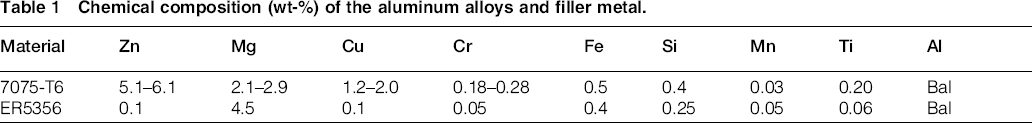
A 2 mm thick sheet of alloy 7075 in tb6 (solution treated + artificially aged) condition was used in this study. Coupons were cut with dimension of 250 mm × 100 mm and placed in a butt joint configuration without a gap between the plates. Chemical compositions for the base and filler metal are shown in Table 1. Each coupon was cleaned with acetone before clamped for welding. Argon shielding gas, at a flowrate of 15 L min− 1, was switched on 3 s before the arc was struck. A torch angle of 10° from the perpendicular axes was used, and welding was carried out using the robotic CMT technique. Suitable welding parameters were selected and are given in Table 2.
Chemical composition (wt-%) of the aluminum alloys and filler metal.
Welding parameters.

Transverse section of the weld joint was polished using a standard metallographic procedure. Polished specimens were etched with Barker's reagent [5 mL HBF4 (48%) in 200 mL water]. The microstructures of different zones of interest, such as base metal (BM), HAZ and WM, were analysed on optical microscope using polarised and unpolarised light. Porosity percentages and imperfections were studied and evaluated from the cross-section of the bead. Additionally, a scanning electron microscope equipped with energy dispersive spectroscopy (EDS) was employed to investigate the intermetallic phases.
The microhardness of WM was tested with the help of a Vickers hardness testing machine according to ASTM E384-11e1 with a 0.1 kg load, 0.35 mm between indentations in the weld and adjacent areas, and 0.5 mm between indentations in BMs. Measurements were conducted through the centre of welded joints across the BM, HAZ and WM. The weld bead was ground flat, and tensile samples were prepared in accordance with DIN 50125. 23 Tensile specimens were machined from transverse and longitudinal specimens containing the weld in the centre of the gauge length (T specimen) and along the WM (L specimen). Six samples were used to calculate the average yield strength and tensile strength of the joints. It is worth noting that transverse weld specimens provide a measure of joint efficiency in terms of strength but do not provide an accurate ductility measurement of the weld. However, the longitudinal weld specimens are more representative of the WM properties and joint formability. 24 The test was carried out by tensile machine at room temperature, and the displacement speed was 0.5 mm s− 1.
Results and discussion
Materials and microstructure
The 7075-T6 alloy achieves its high strength from a series of precipitates such as MgZn2, Al2Mg3Zn, FeAl3 and CuAl2.25–27 The microstructure of the BM has revealed grains elongated along rolling direction as it is shown in Fig. 1a. Additionally, varieties of precipitates (Fig. 1b) include coarse particles of Al2CuMg, and small particles of MgZn2((Al,Zn)2Mg( and Al–Mg–Zn phases were prevalent as suggested by EDS analyses. The small and finely uniform dispersed precipitates were formed as a result of aging treatment.
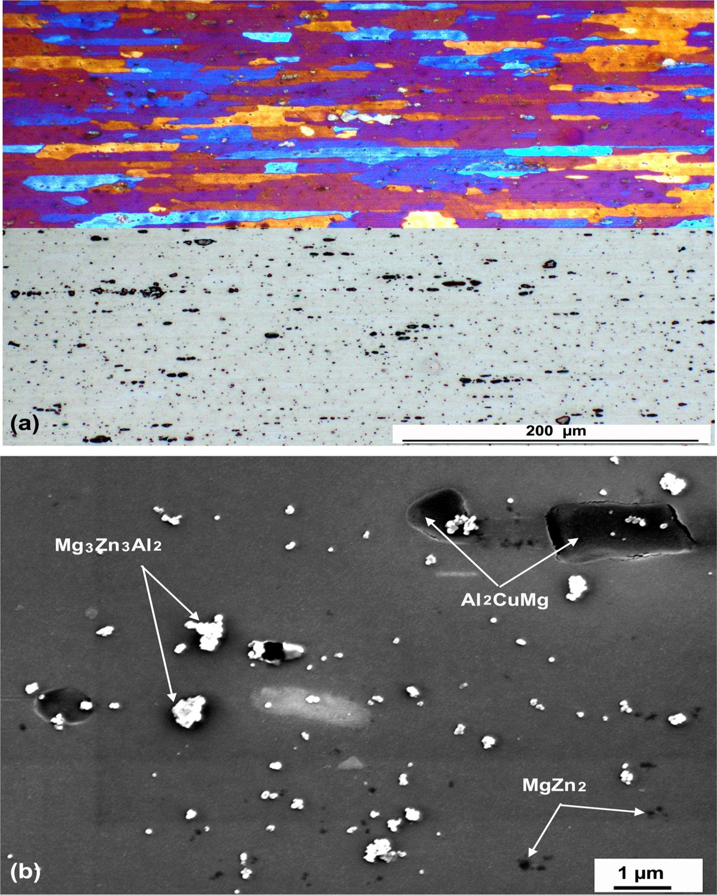
Optical microstructure with polarised (top) and unpolarised (bottom) light image (a) and SEM image (b)
Figure 2 illustrates the cross-sectional and the weld surface appearance of representative joint. It is clear that the joints have good weld profiles in cross-section and good neat bead profiles. Consistent, tight and uniform ripples indicate a strong weld, free from contamination or cracks. This observation is typical for automated welding processes. Joints have almost no spatter, which confirms the ability of the CMT process to produce joints with virtually no weld spatter. It was detected that there were some pores in the joint cross-section, and most of them were distributed in the middle and bottom of the joint. The detected pore sizes range from < 2 to ∼125 μm and, in the worst case, represent almost 1.1% of WM cross-section area. It is reported that tensile strength is not reduced until the porosity level increased to >1%. 28
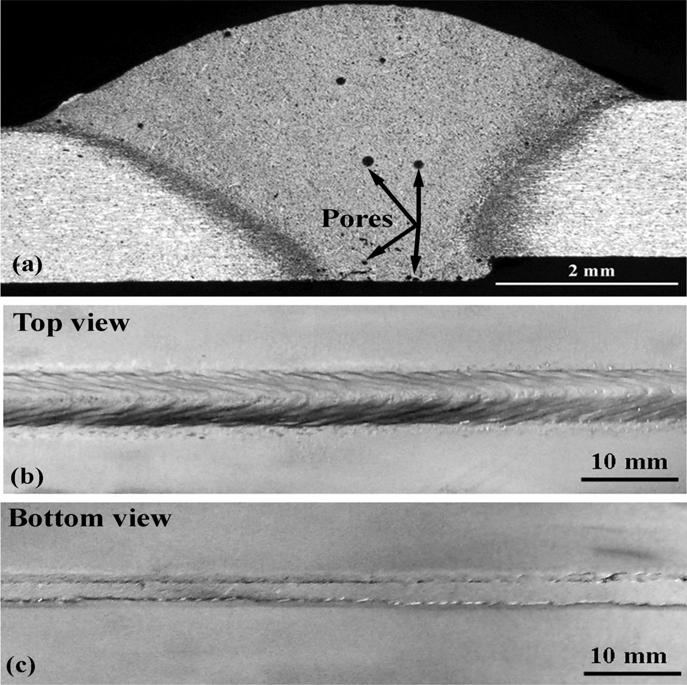
Cross-section macrostructures of joint representative joint (a), weld bead profiles from top view (b) and bottom view (c)
The microstructure of the WM has revealed equiaxed grains with grain sizes of ∼120 μm as shown in Fig. 3a. The grains contain dendritic structure, and owing to the temperature gradient, the edge of the weld has more columnar dendrites in contrast to dendrites found at the centre of the weld. SEM and EDS analysis revealed the presence of interdendritic phases rich in Al, Mg and Zn. Al–Zn–Mg ternary phase diagram suggested that these phases are Al solid solution in addition to MgZn2[Mg(Al,Zn)2], Mg2Zn11, (Al,Zn)49Mg32 [29, 30] The WM SEM micrograph is shown in Fig. 3b.
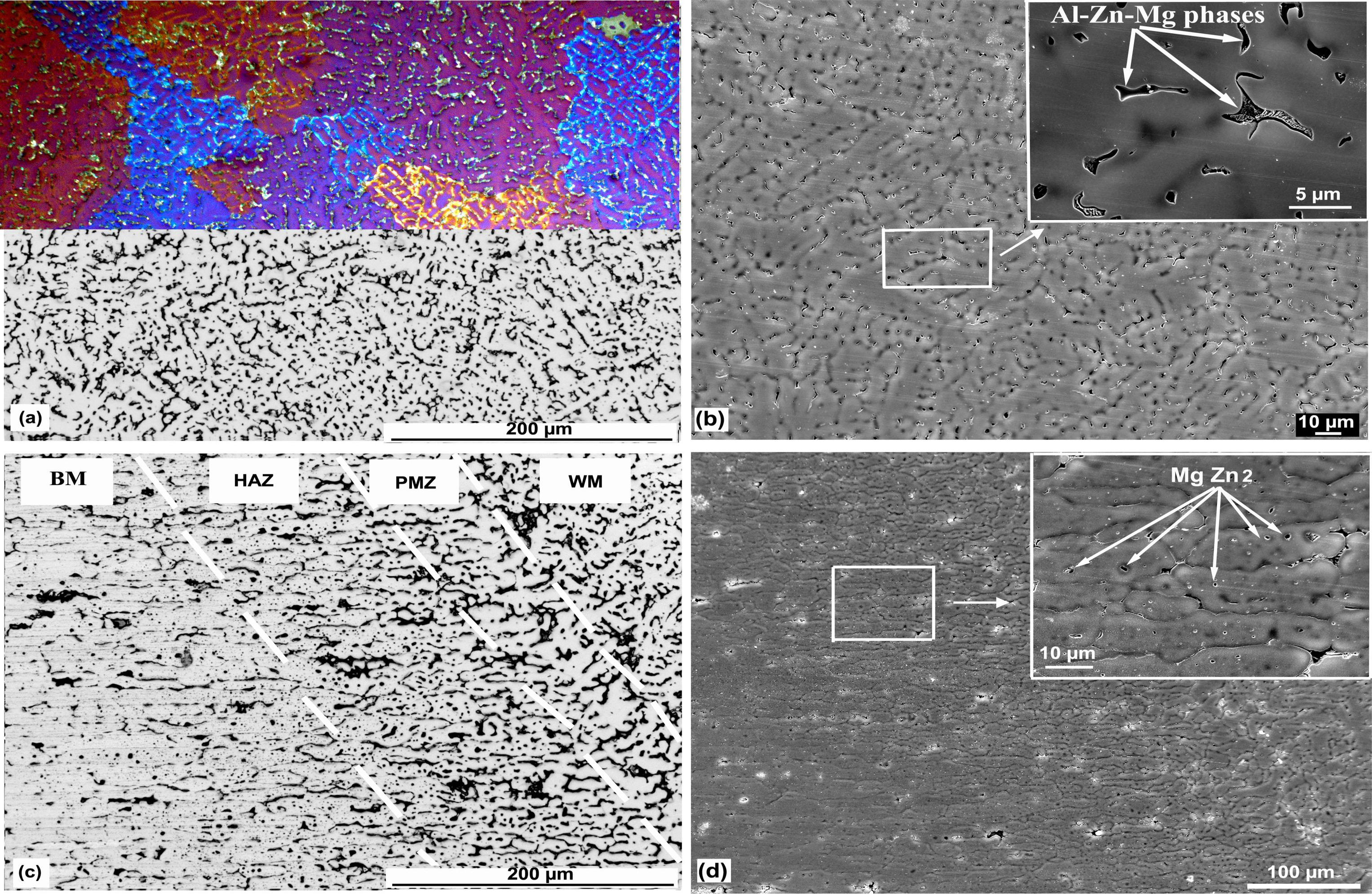
a polarised (top) and unpolarised (bottom) optical light microstructures of WM; b SEM image of WM; c HAZ/WM interface; d SEM image of HAZ/WM interfaceTypical microstructures of different joint regions
The area in between the WM and BM can be divided into the partially melted zone (PMZ) and the HAZ as indicated in Fig. 3c. The PMZ corresponds to the area where high temperature causes dissolution of precipitates into the solid solution, and the insufficient time during cooling was not enough to reprecipitate. Meanwhile, in the HAZ, the temperature was quite high to cause growth and coarsening of preexisting precipitates (overaging process). This phenomenon is consistent with other studies.31–33 EDS analysis of the coarsened precipitates (Fig. 3d ) proved the distribution of MgZn2 in the HAZ grains based on the stoichiometric composition (32.6 Zn, 14.7 Mg, 52.7 Al, at-%).
Microhardness
The microhardness distribution along the joint is shown in Fig. 4a. It is observed that the lowest hardness values are measured in the WM. In fact, several factors are controlling the hardness of the WM. The main factors are the alloying elements in solid solution; precipitate volume fraction, morphology and size; and grain size. During welding, the elements in the WM are a combination of the filler metal and the dilution from the BM. The strengthening elements Zn and Mg sharply decrease in the WM because these elements are prone to evaporation during welding.26, 34–36 The chemical analysis of the WM in at-% was 1.83 Mg, 2.07 Zn, 0.28 Cu and 95.82Al. After experiencing a melting process, the solidified alloy is in the form of supersaturated solution, and few particles precipitate from the supersaturated solid solution. Furthermore, the WM grain size has been coarsened after the solidification process compared to the BM. Thus, the lower microhardness in the WM is due to the action of low amount of alloying elements, lack of precipitates and grain size coarsening.
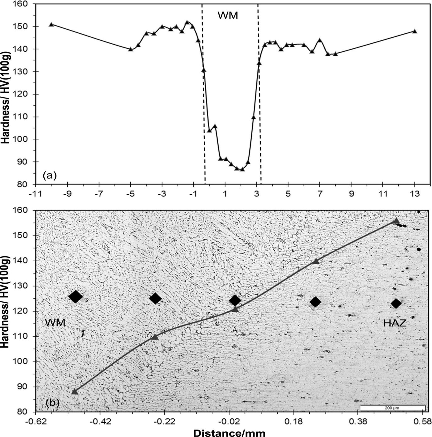
Microhardness profiles across welded joints (a) and at WM/HAZ interface (b); 0 mm position is taken as left most edge of WM
As expected, the hardness distribution is a steady increase from the WM to the direction of HAZ as clearly shown in Fig. 4a and b. This phenomenon is mainly owing to the solid solution strengthening in the PMZ and the presence of precipitates in the HAZ. The BM showed the highest hardness level due to the unchanged tb6 treatment.
Tensile properties
The yield strength, tensile strength and elongation for BM and welded joints are shown in Fig. 5. The mechanical property coefficients of the joints in L specimen (known as the ratio between the mechanical properties of a welded joint and that of BM) were 77%, 60% and 69% for yield strength, ultimate tensile strength and elongation respectively. The corresponding ratios with respect to T specimen were 65%, 55% and 16%. It is interesting to note that L samples were generally higher in mechanical properties than T samples. In the case of T welded joints, since the weld is weaker than the surrounding transverse areas, it possesses all plastic deformation and the fracture took place at a low tensile load. On the other hand, L welded joints display entirely different tensile behaviour. The different zones have different resistance to deformation due to difference in microstructure, grain size, precipitate size and distribution. The increase in strength properties compared to T joints is due to the presence of the stronger HAZ and BM longitudinal to WM and resisting the deformation.37, 38
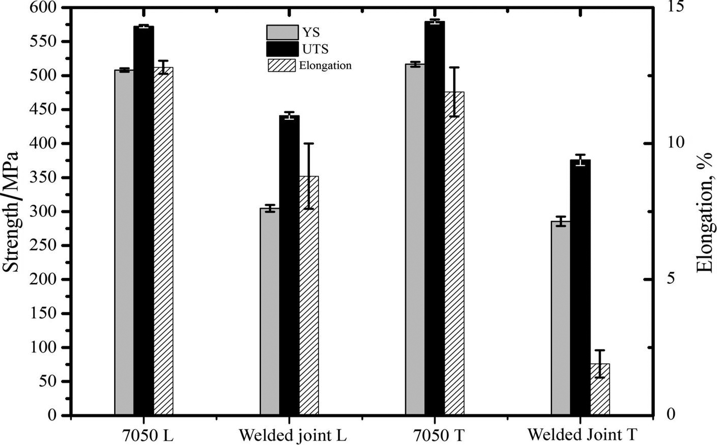
Mechanical properties of weld joints
The heat input has great influence on the strength loss due to welding. A greater heat input produces a wider softening region, a sharp decrease in strengthen elements and precipitated particles. While CMT uses a heat input lower or close to 0.1 kJ mm− 1 at this work, other conventional MIG or tungsten inert gas (TIG) processes use 1–4 kJ mm− 1.25, 34–36 As a result, the loss of alloying elements and/or precipitates is clearly reduced in case of using CMT process. Therefore, the obtained results using CMT process are quite better than its comparable results while using MIG or TIG welding for the same alloy. Additionally, it could be concluded that CMT process achieved mechanical characteristics comparable to FSW and LBW since these processes use low heat input as well.25, 35, 39–44 We should mention here the advantages of CMT in comparison with other welding processes with respect to its higher welding speeds, simplicity and easy automation, low skill required for operation, availability, cost and economic issue.
When the joints are loaded in tension, the WM constitutes the weakest area where all the strain concentrates. As a result, examination of the tensile samples after fracture indicated that the fracture always occurred within the WM as indicated in Fig. 6a and its enlarged view in Fig. 6b. From the SEM image of the fracture morphology, it is noted that the joint was fractured along the dendrites with quasi-cleavage brittle fracture surfaces, which are characterised by river and tearing ridge patterns (Fig. 6c).
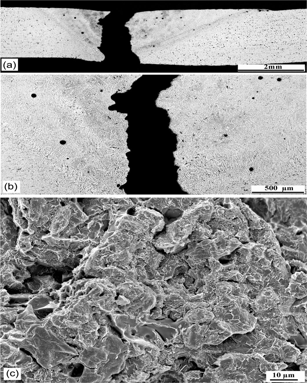
a fracture path after performing tensile test; b enlarged view of fractured area; c pattern of fracture surface
Further research work is necessary to optimise CMT joints of high strength aluminium alloys in order to improve their mechanical properties. One approach could be the development of an applicable new filler wire containing scandium or vanadium. These fillers are expected to be much stronger than other high strength alloys, exhibit significant grain refinement and strengthen welds. Another approach could be a post-weld heat treatment of the joints in order to improve the mechanical degradation in WM and HAZ.
Conclusions
On the basis of the present results, the following conclusions were reached.
Defect free CMT 7075-T6 joints were produced without spatter, cracks and very low porosity. The strengthening elements Zn and Mg sharply decrease in the WM area compared to the BM. Meanwhile, coarsening of MgZn2 precipitated was observed clearly in the HAZ. The joints exhibited minimum microhardness in the WM and slight hardness decrease in HAZ compared to the BM. The joint had mechanical property coefficients of 77%, 60% and 69% for yield strength, ultimate tensile strength and elongation respectively. The failure positions of welded joints were all located in WM, where the microhardness value was the lowest in the entire welded joints. CMT welding process is capable to produce joints with mechanical characteristics better than the conventional MIG and TIG processes and comparable to FSW and LBW processes.
Footnotes
Acknowledgements
We would like to thank Austrian Institute of Technology (AIT) for the financial support in this project. Moreover, we would like to thank Austrian Research Promotion Agency (FFG), the Federal Ministry for Transport, Innovation and Technology (bmvit), and the State of Upper Austria for sponsoring this research work in the framework of COMET.