
Abstract
In this study, filling friction stir welding was used to remove the exit hole of friction stir welding lap joints made from AA5456 sheets. For this purpose, the exit holes were filled by consumable pins with various geometries and different pin applying methods. Then, the structures and mechanical properties of the resulting joints were investigated. Results showed that the strength of 7% higher than the strength of the joint with the non-filled exit hole, ∼91% of the corresponding defect free joints, is obtainable with this technique. The best results were found by a pin with 11° cone angle, 8 mm diameter and 7 mm length, and with a 6 mm plunge without rotation.
Introduction
Friction stir welding (FSW) is a solid state welding process. 1 This process is increasingly used for joining Al alloys, and its industrial use is expected to increase. 2 In this method, the plates are clamped together rigidly in butt or lap conditions. A stirring tool with a suitable geometry is pressed against abutting or overlapping plates and moves along them. An important part of the tool is a probe (i.e. pin), which protrudes from the base of the tool shoulder. 3 The heat generated by friction at the shoulder and pin surfaces softens the material being welded. 4 Although the implementation of FSW has been shown to reduce the number of weld defects, as compared to other processes, it still has various defects. 5 Welding defects such as groove, cavity and kissing bond may be formed when improper parameters or technological conditions are used.6, 7 However, because of the use of the pin, an exit hole is present after FSW. 8 Both lap shear and cross-tension strengths are limited due to the relatively small bonding widths6, 9 and stress concentration 10 in the hole.
Application of fusion welding technology for filling the exit hole has significant limitations,6, 11 such as the requirements of gas shielding of the weld pool, removal of oxide layers before or during the welding process, porosity formation, cracking and strength loss in the weld zone.12, 13 Leaving the exit hole in the run off plate or run off wedge 14 is limited to structures in many cases. Ding and Oelgoetz 11 invented retractable pin tools wherein the pin can be incrementally withdrawn from the work pieces. A new technique of self-refilling FSW has been proposed by Zhou et al. 15 , where conventional FSW process was transformed by adopting a series of pin tools with gradual change in geometry. However, a wide and shallow exit hole like retractable pin FSW still remains at the weld centreline due to the inadequate material to fill the exit hole.
The other method is friction plug welding, which has been developed in two varieties; first, friction tapered plug welding (FTPW) that has been invented by TWI 9 , and second, friction pull plug welding. 16 In this method, the exit hole was removed by pushing or pulling (after drilling) a rapidly rotating plug. Cui et al.17, 18 used FTPW for S355 steel, and Metz and Barkey 5 used FTPW for 2195 Al–Li alloy. However, due to the use of the tapered plug without shoulder, stress concentration is going to be formed at the interface. 9 Like FSW, in friction stir spot welding, the remaining exit hole in the centre of the weld is an important problem. Therefore, refill friction stir spot welding (FSSW) technique was developed by Helmholtz–Zentrum Geesthacht to solve this problem. The main difference between refill FSSW and the conventional method is that both probe and shoulder tools are retractable at the end of the process, leaving no exit hole on the surface of the plate.19, 20 Another variant of FSSW was developed by Venukumar et al. 21 In their technique, the conventional FSSW was modified by adding an additional plate called filler plate, instead of complex and expensive FSSW refill machine.
Recently, a new technique called filling friction stir welding (FFSW) has been proposed by Huang et al.6, 9, 22 based on the basic principle of FTPW. The FFSW consists of a consumable tapered pin, instead of the original non-consumable stir pin, fixed in a concentric larger diameter non-consumable shoulder. Compared to the FTPW process, excess sections of the plug could be cut automatically under proper tool design and process parameters during the FFSW. 8 Unlike the conventional FSW tool, the tool used in the FFSW process has three primary functions, i.e. localised heating, material flow and filler material. 6
In this study, removing the exit hole of FSW lap joints by FFSW method was investigated. For this purpose, AA5456 sheets with dissimilar thicknesses and tempers were used. The 5456 aluminum alloy is used in many marine and aerospace structures due to its superior strength and corrosion resistance.23, 24 The main purpose of this study was to investigate the FFS weld structures and the effect of geometry, plunging and moving technique of the tools on their mechanical properties and probable defects. For this purpose, nine distinct AA5456 consumable pin geometries were designed and applied in this research. Also, four different plunging and moving methods were investigated. The place of fracture initiation, the mode of crack growth and the fracture surface characteristics of the FFSW tensile shear specimens were also studied.
Experimental
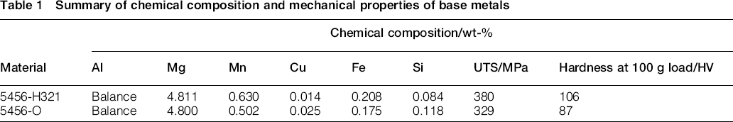
In this investigation, AA5456-H321 and AA5456-O aluminum alloy sheets with thicknesses of 5 and 2.5 mm respectively were used and lap joined by the FSW process. The nominal chemical compositions and mechanical properties of the alloys are presented in Table 1. AA5456 pins were designed for carrying out the FFSW experiments. Prior to welding, the overlapped surfaces were first cleaned by acetone and then burnished by abrasive papers to remove oxidation films and other impurities.
Summary of chemical composition and mechanical properties of base metals
The thick sheet was placed as the top member with 50 mm overlapped part, and after that, the assembly was tightly clamped onto the work table by a welding fixture. The welding direction (WD) was perpendicular to the sheet rolling direction (RD). According to previous investigations25–27, when the retreating side (RS) of the top sheet is loaded, the higher lap shear strengths can be obtainable. Thus, in the present study, the welds were produced in such a way that the RS of the top sheet was loaded, as shown in Fig. 1.
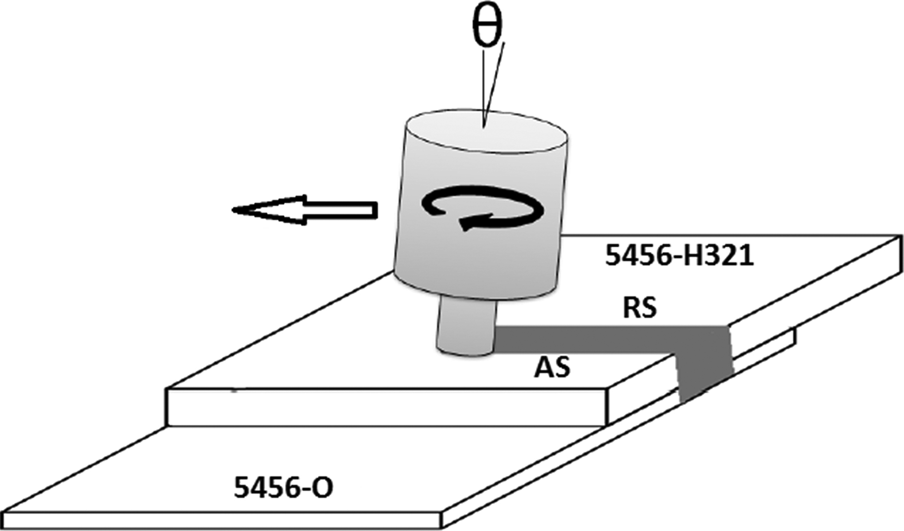
Schematic representation of friction stir lap welding experiments
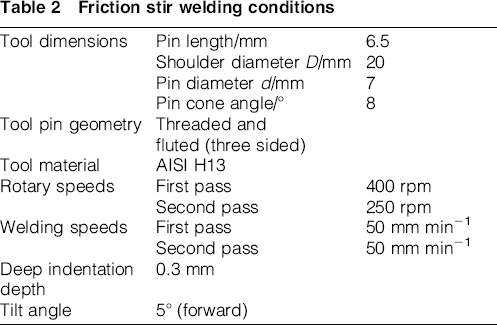
The welding tool was rotated in the counterclockwise direction, plunged into work pieces with the speed of 20 mm min− 1 and moved forward perpendicular to the RD of the work pieces. The welding experiments were carried out in two passes. The tool angles in the first and second passes were the same, but the rotating and welding speeds were different. The FSW conditions and the tool features are listed in Table 2.
Friction stir welding conditions
The pin tool used for FFSW was different from the pin used for FSW. The pin in FSW exits at the end of the process, and its effect remains as an exit hole (Fig. 2); however, in FFSW, the pin tool is consumed to fill the exit hole, which is produced in FSW. The material used for the filling was the same as the parent sheets’ material. The used tools for FFSW, consumable pin and non-consumable shoulder tools are illustrated in Fig. 3. The remaining exit hole after welding was in situ filled by pins having different geometries and techniques, according to Table 3. The FFSW pins plunged into the remaining exit hole with 5° tilt angle and constant rotational and plunging speeds of 500 rpm and 1 mm min− 1 respectively.
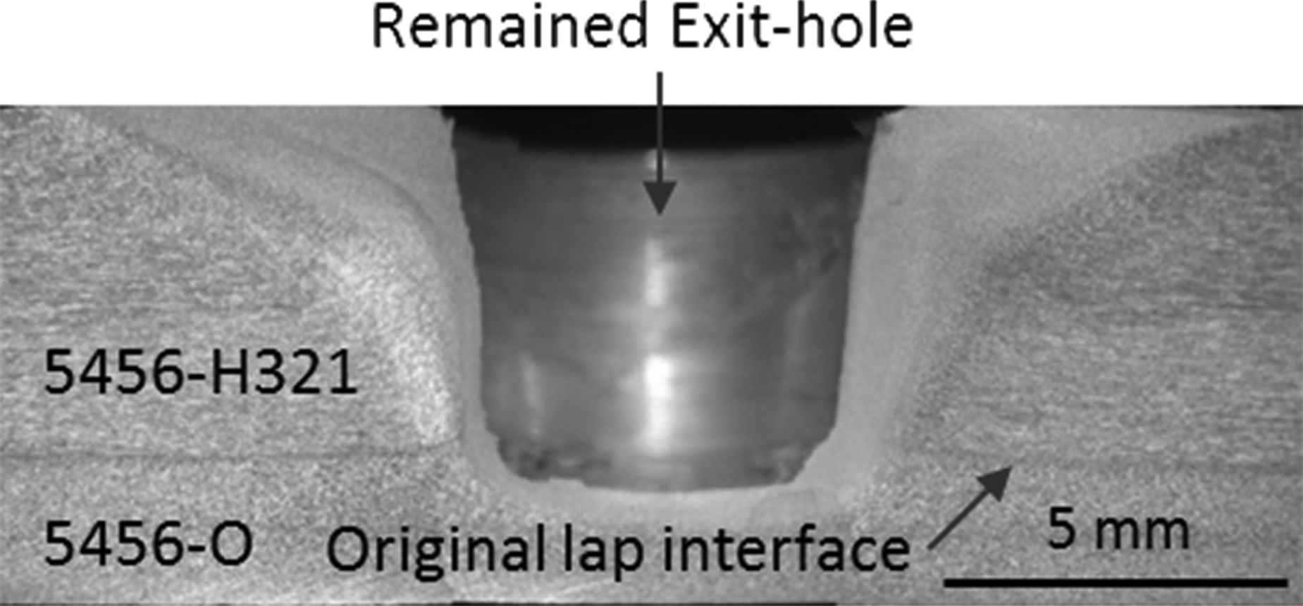
Cross-section of remained exit hole at end of weld line
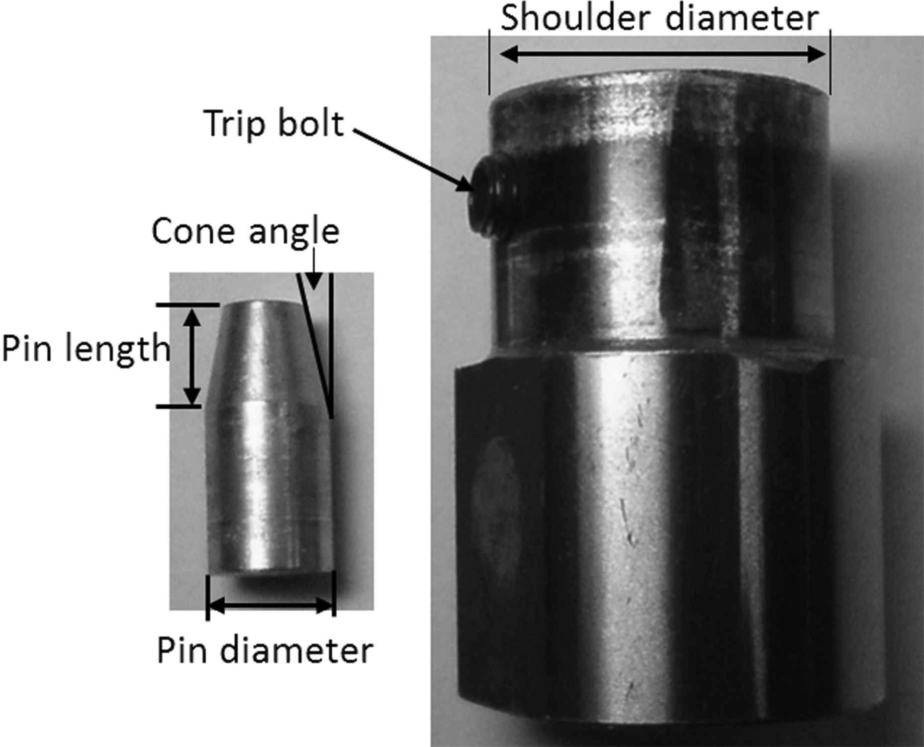
Illustration of used tool for FFSW; consumable pin and non-consumable shoulder tools
Filling FSW geometry and technique conditions
The shapes of the pins were in two types, which are shown schematically in Fig. 4. The geometry of these two types is given in Table 3. It should be noted that the type K1 pins had two different cone angles, but the shape of these pins is not full conical (Fig. 4a). The type K2 pins had different cone angles, pin lengths and diameters. The type K2 pins were full conical, as shown in Fig. 4b. The pin angles were selected so that different contact situations, between pin and exit hole walls, occurred during penetration into the exit hole.
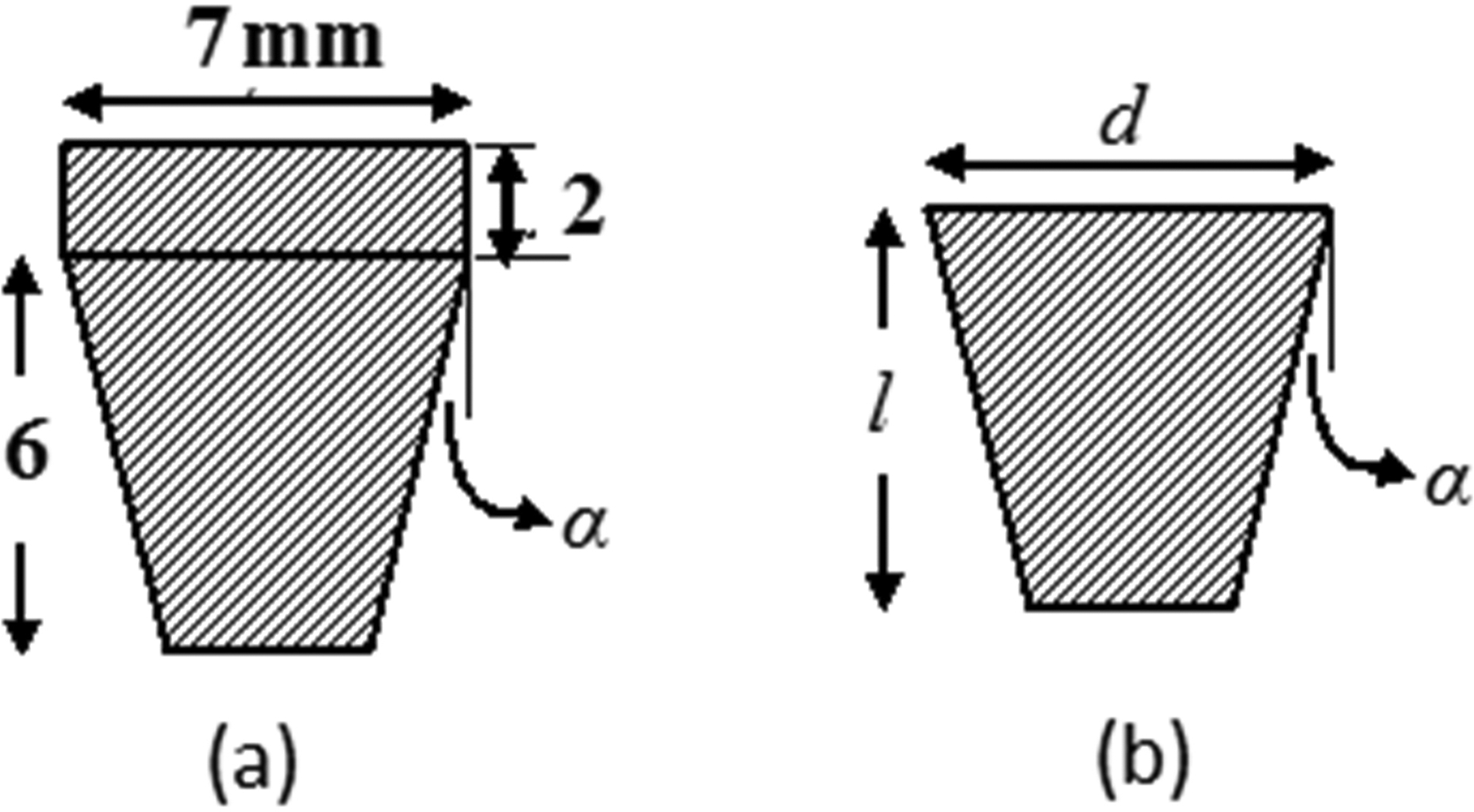
a type K1; b type K2
Four plunging and moving methods were investigated. It should be noted that the pins with various geometries were applied with technique tbl1, and then the geometry having the best result was used with the other techniques. In technique tbl1, the pin penetrated into the exit hole with constant rotating and plunging speeds, and when the shoulder touched the base metal surface, it plunged into the sheet as much as 0.2 mm and then rotated for 30 s without plunging. At the end of the joining process, the spindle of the welding machine was stopped and then restarted to separate the consumable pin from the weld. In techniques tb2 and tbl3, the pin penetrated into the exit hole 5 and 6 mm respectively and then rotated, and the remaining process was the same as technique tbl1. In technique tbl4, instead of 30 s rotation after plunging, the pin moved along the weld line, similar to FSW, with 50 mm min− 1 speed. After the welding experiments, the produced joints were evaluated from the viewpoint of defect formation, and then they were shear tensile tested to determine the best pin geometry and suitable pin applying method.
The metallographic specimens were cross-sectioned from the middle of the filled zone perpendicular to the WD. Then, the specimens were polished using a 0.3 μm alumina and etched with the modified Poulton's reagent. A stereo microscopy was applied to characterise the weld profile and structure.
The tensile shear tests were carried out at room temperature and under constant crosshead speed of 2 mm min− 1. The tensile shear specimens with a width of 25.4 mm and an overall joint length of ∼250 mm (Fig. 5), according to AWS D17.3/D17.3M:2010 28 , were tested perpendicular to the WD. Due to the asymmetric characteristic of FSW, all the welds were produced in such a way that the advancing side was always located near the top sheet edge, and the RS of the upper sheet was loaded, as schematically illustrated in Fig. 5. Supporting sheets with similar thicknesses were placed underneath the top sheet and above the bottom sheet to prevent the occurrence of misalignment during the tensile shear testing of the lap joints. The fracture locations of the tensile shear testing specimens were also studied. Then, the fracture surfaces were investigated using scanning electron microscopy.
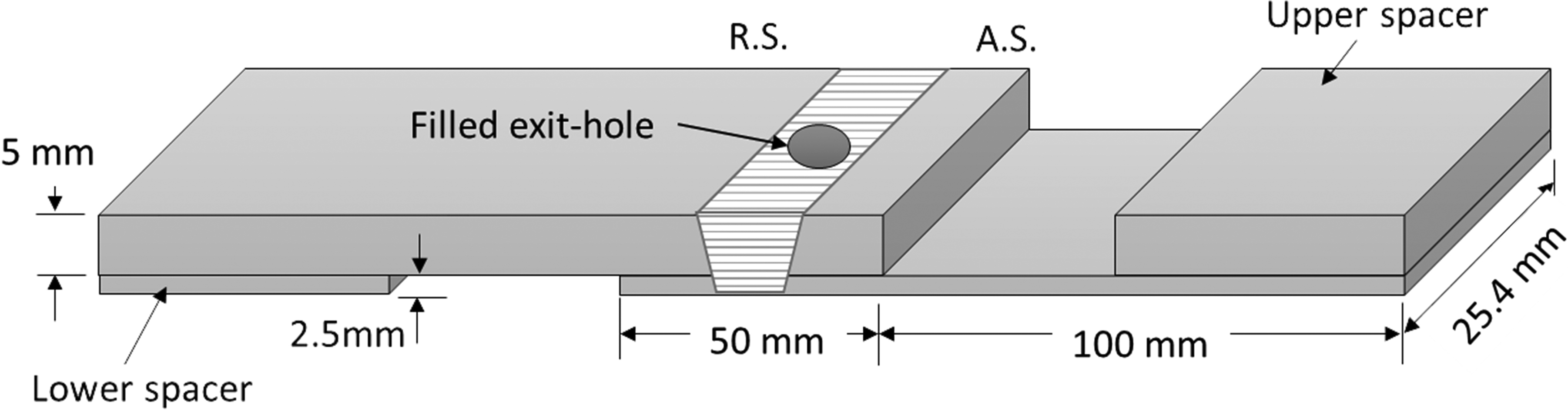
Schematic illustration of tensile shear test specimens and supporting spacers
Results and discussion
An image of the filled exit hole by FFSW is shown in Fig. 6. It reveals that the surface of the joint produced by FFSW process is suitable.
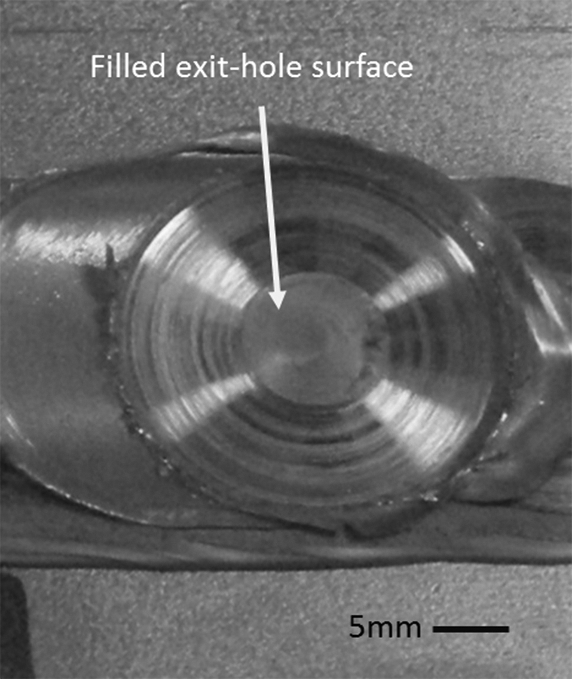
Surface of filled exit hole by FFSW (specimen K2T1D8L8α11)
A macroscopic view of the cross-section of the FFSW joint produced by type K1 pin and technique tb1 with two different cone angles is presented in Fig. 7. The results show high discontinuity in the filled exit hole due to the unsuitable geometry of the pins. In type K1 pins, two different cone angles were used. The results showed that when the cone angle is high (10.5°, Fig. 7a), continuity in the weld is lower than when cone angle is low (8°, Fig. 7b). The reason can be related to the manner in which the pin touches the exit hole walls. The FFSW process includes three main steps: a friction step, a stirring step and a joining step. 6 When the cone angle is high, the tip of pin first contacts with the bottom of exit hole during the penetration, and low friction is generated. However, when the cone angle is low, the pin contacts with the exit hole wall during plunging. Thus, improper touching of pins leads to insufficient friction, which causes the other FFSW steps to incomplete.
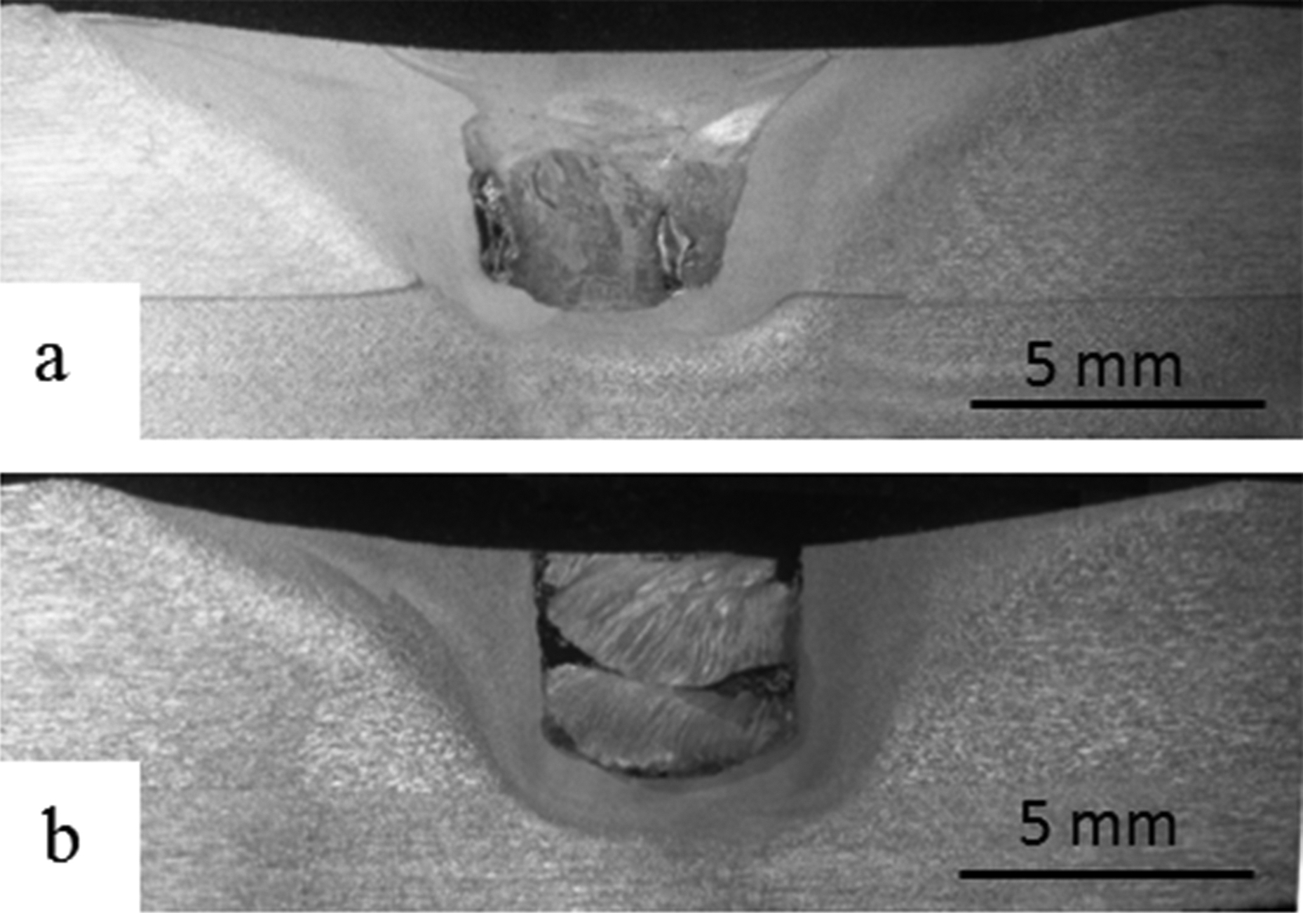
Macroscopic view of cross-section of filled exit hole by type K1 pins for two different specimens of a K1T1D7L8α8 and b K1T1D7L8α10·5
Figure 8 shows a macroscopic view of the cross-section of the FFSW joints produced by type K2 pins with different lengths, diameters and cone angles. Among the cone angles, 11° formed a defect free weld structure (Fig. 8d), and among the pin lengths, 7 mm had the best structure (Fig. 8d). Both pin diameters of 7 and 8 mm showed proper continuity. Thus, for selection of the best diameter, their mechanical properties were tested.
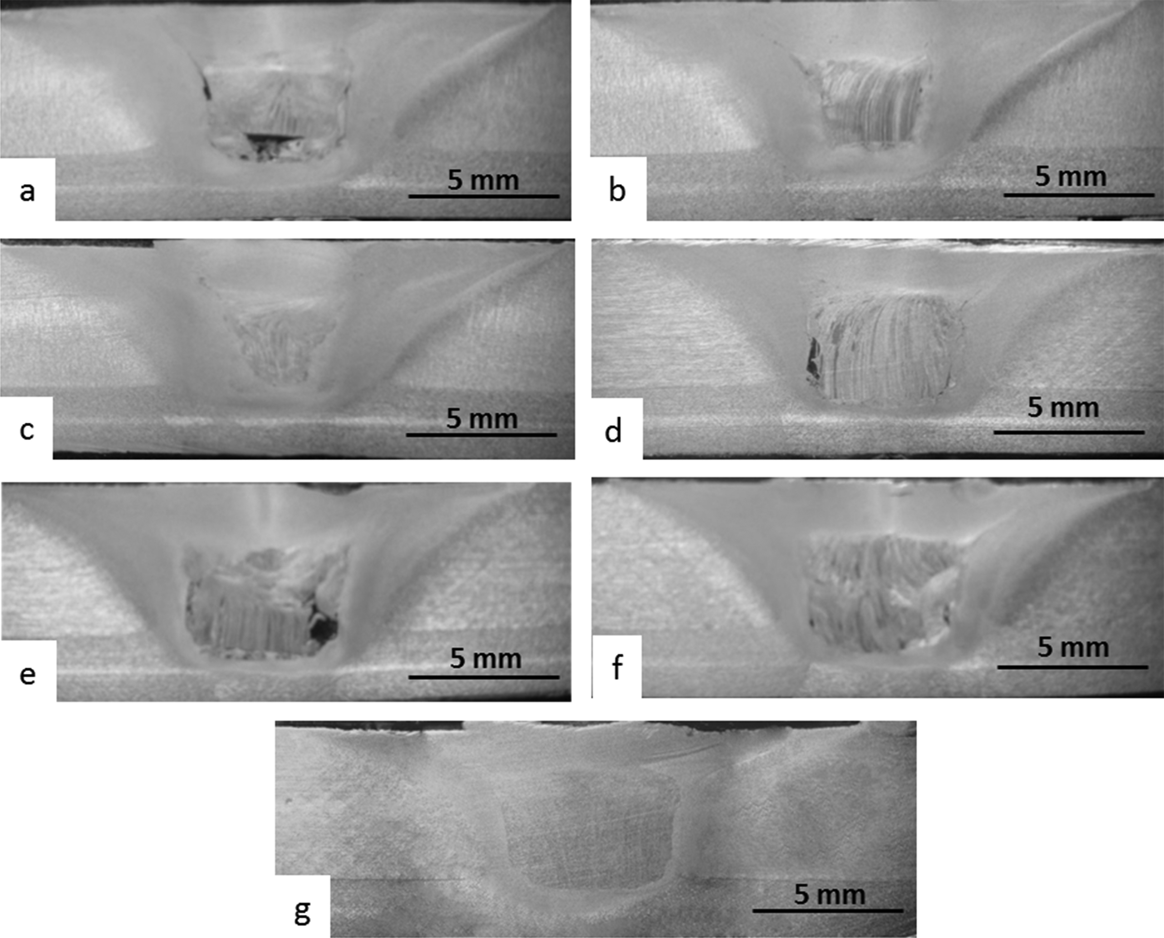
Macroscopic view of cross-section of FFSW joint produced by type K2 pin with different geometries for specimens of a K2T1D8L7α6·5, b K2T1D8L7α9·5, c K2T1D8L7α11, d K2T1D8L7α14, e K2T1D8L6α11, f K2T1D8L8α11 and g K2T1D7L7α8
Figure 9 shows a macroscopic view of the cross-section of the FFSW joints made by different plunging and moving techniques. Results reveal that technique tb4 (Fig. 9c), i.e. moving plunged pin in the welding line direction like the movement of steel pin in FSW, is unsuitable because the upper parts of the filled exit hole peeled when the pin tools moved. This could be due to the lower shear strengths or high travel speed (50 mm min− 1) of the aluminum pin. Figure 9a and b illustrates the results of techniques tb3 and tbl2. According to the observations, tb3 has a defect free joint but tb2 has some discontinuities in the lower portion of the filled exit hole. Any discontinuity, particularly along the interface, acts as an initiation site for fracture, because higher stress concentration occurs in this region. 29
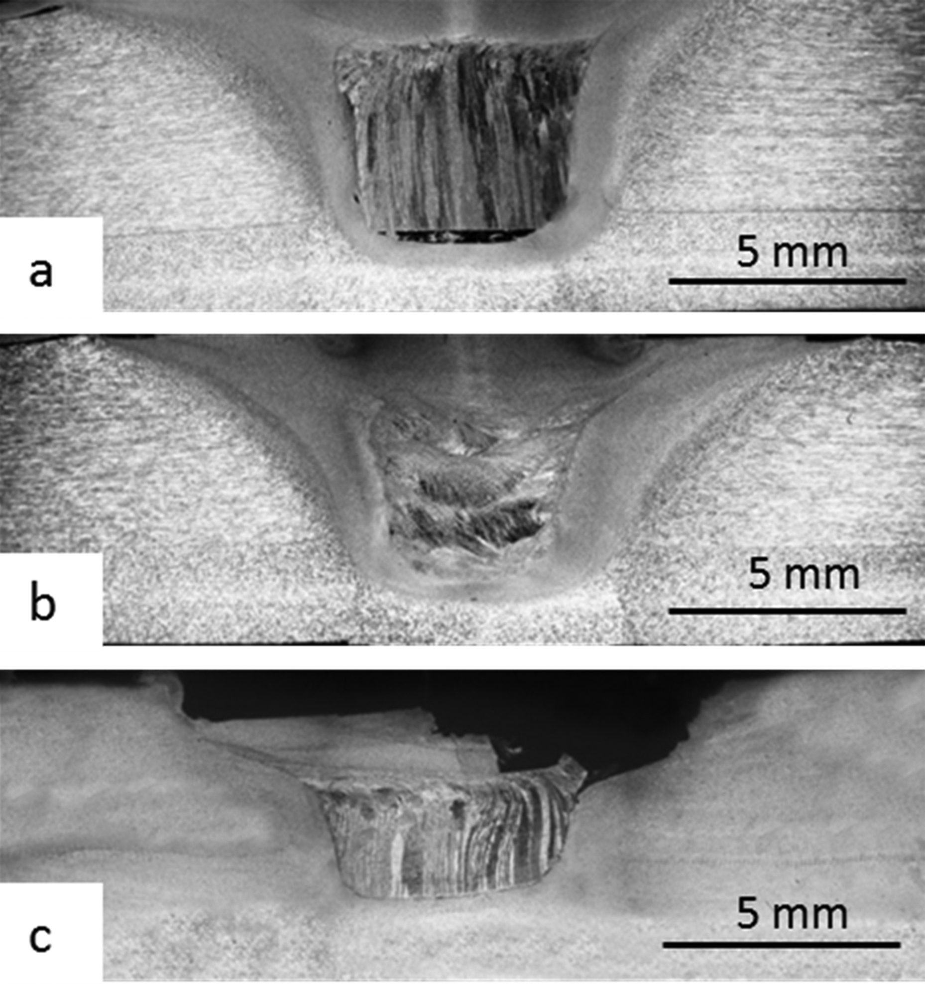
Macroscopic view of cross-section of FFSW joint made by similar pin geometries and different pin applying techniques for specimens of a K2T2D8L7α11, b K2T3D8L7α11 and c K2T4D8L7α11
Figure 10 shows the tensile shear strengths of the filled samples that have suitable soundness (without important discontinuity) with respect to the others. Furthermore, for better comparison, the tensile shear strengths of the samples of the non-filled exit hole joint and continuous weld (without the exit hole) have also been given. The results show that the non-filled sample has 84% of the FSW joint strength; however, the highest FFSW joint strength, which was achieved by technique tb3 and type K2 pin geometry with 8 mm diameter, 7 mm length and 11° cone angle (K2T3D8L7α11), is ∼91% of the FSW joint strength. Therefore, the strength of the joint was improved ∼7% by the FFSW method, and also, the remaining exit hole was filled by a material that was similar to the base metal.
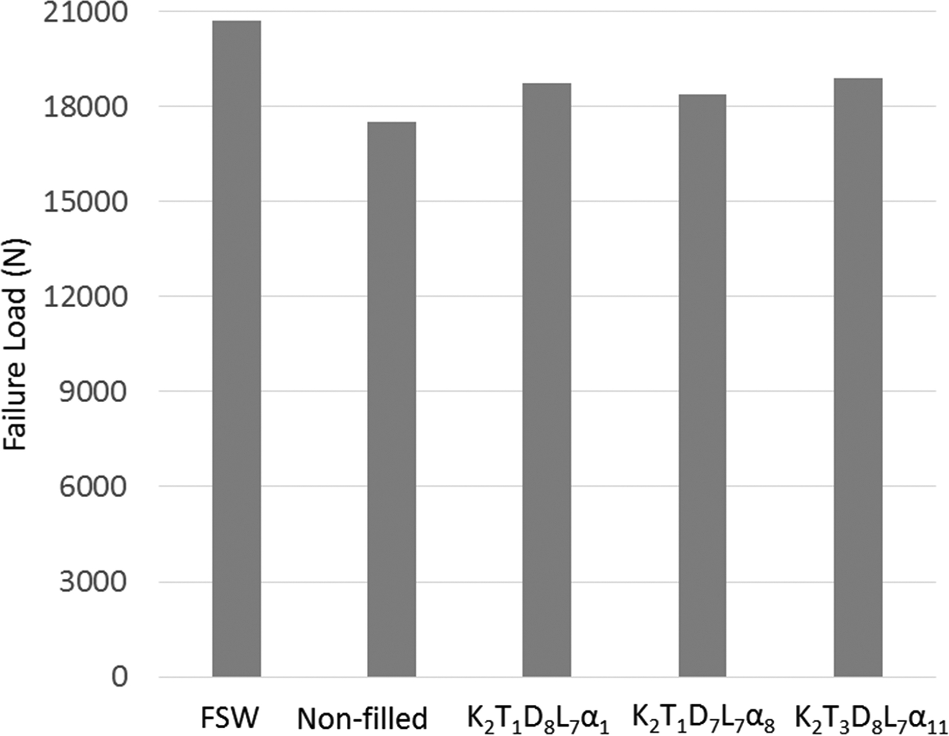
Tensile shear strengths of joints
As shown in Fig. 9, techniques tb2 and tb4 were not able to produce defect free joints. However, tb3 and tb1 had an appropriate joint structure. As mentioned before, two pins in the tb1 technique had good continuity (K2T1D8L7α11 and K2T1D7L7α8). Figure 10 shows that K2T1D8L7α11 has higher shear strength than K2T1D7L7α8. It must be noted that FSW pin tools had D7L6.5α8 geometry. In spite of the high similarity of the K2T1D7L7α8 specimen pin to FSW pin tools, with difference of 0.5 mm higher length (in order to remove low income material in filling), the K2T1D7L7α11 specimen showed better results. It can be concluded that the best geometry is not absolutely similar to the non-consumable one. Technique tb3 has a slightly better result than technique tbl1.
To further clarify the fracture features of the FFSW welded joints, the appearance of the K2T1D8L7α11 joint after tensile shear test is shown in Fig. 11, and the SEM images obtained from three different locations of its fracture surface are shown in Fig. 12. According to Fig. 11, fracture occurs through the filled exit hole interface and perpendicular to the loading direction. The fracture surface of the filled zone sides (region ‘A’ in Fig. 11), which belong to the previous FSW, is characterised by large and deep dimples with tearing edges (Fig. 12a). Thus, its features represent a ductile fracture mode. There are distinct differences between the filled exit hole and the FSW region of the fracture surface. At the upper part of the filled exit hole (region ‘B’ in Fig. 11), the fracture surface contains some shallow and deep dimples (Fig. 12b), which is a typical feature of good ductility. However, the fracture surface at the lower part of the filled zone is different (region ‘C’ in Fig. 11), and it seems that enough mixing has not been occurred in this region (Fig. 12c).
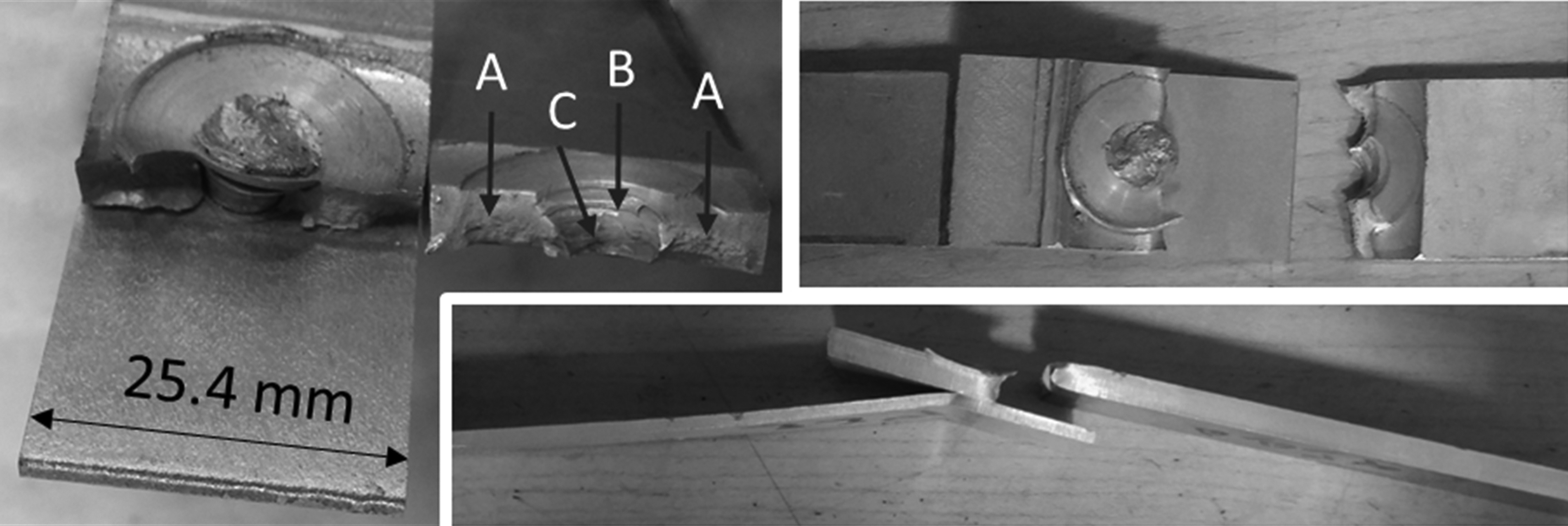
Appearance of K2T1D8L7α11 joint after tensile shear test
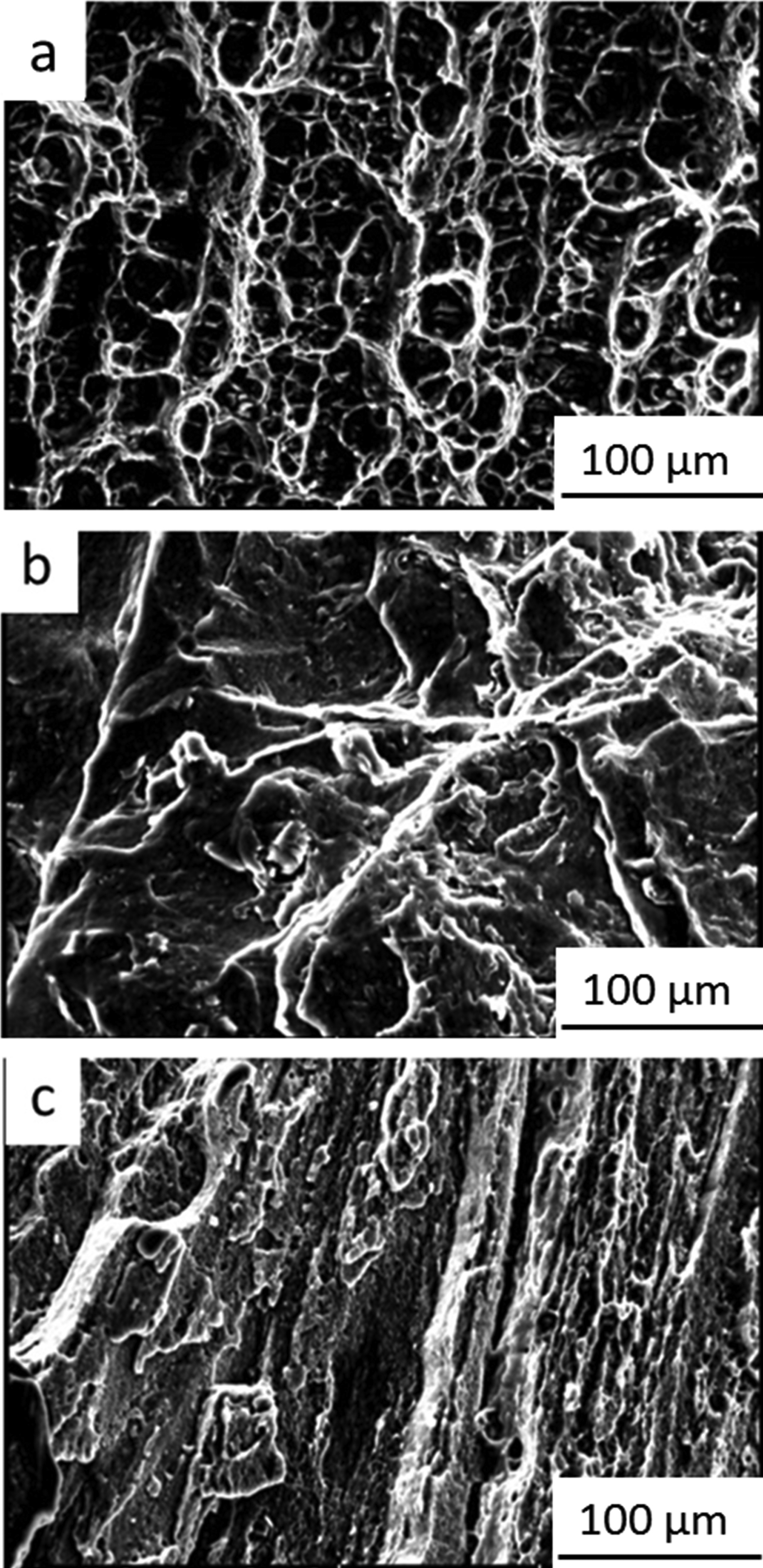
a FSW region, edge of filled zone; b upper part of FFSW region; c lower part of FFSW region
Conclusions
In this investigation, an attempt has been made to explore a new technique for the FFSW of lap joints in order to repair the exit hole remaining after the FSW process. The FFSW was carried out by a steel shoulder and aluminum alloy joining pins with various geometries and plunging methods. Based on the results, the most important findings are the following.
Macroscopic observations confirmed that defect free lap joints are successfully obtainable by the FFSW method.
The pins that were not fully conical (type K1) did not result in sound welds. Their unsuitable geometry caused an incorrect contact at the pin/exit hole faying surface, and consequently, enough friction and stirring were not attained.
Between the full conical pins (type K2) applied with a rotating plunge (technique tbl1), the pin having the diameter, length and cone angle of 1 mm, 0.5 mm and 3° respectively higher than those of the non-consumable one demonstrated better results.
Moving the pin in the weld line direction (technique tbl4) and the 5 mm non-rotating plunge (technique tbl2) resulted in unacceptable joints.
The best results were found by a pin with 11° cone angle, 8 mm diameter and 7 mm length, and with a 6 mm plunge without rotation (technique tbl3), with ∼91% of the corresponding defect free FSW joint.