
Abstract
The joints of aluminium matrix composites with high SiC particle content were achieved by vacuum brazing with Al–12Si–1·5Mg–4Ti foil as active filler. The effect of Ni coating and Ti on the wetting behaviour of filler metal on the composite was investigated. Owing to the presence of Ni coating, the wettability of liquid filler metal on the composite was enhanced obviously, and Ti(AlSi)3 intermetallic is in situ strengthening phase in the seam. Sound joints with well appearance were obtained, and the optimised shear strength of the joint reached 109.3 MPa. Capable welding parameters were broadened by the presence of Ni coating and Al–12Si–1.5Mg–4Ti foil as filler for brazing of aluminium matrix composites with high SiC particle content.
Introduction
With unabated rapid development in phase array radars, proper option of electronic packaging materials for T/R modules has become most vital to the success of advanced designs. Traditional metallic and ceramic electronic packaging materials could no longer meet all the requirements. Fortunately, high volume fraction Al–metal matrix composites (Al-MMCs) with SiC particle contents typically ranging from 50 to 70 vol.-% possess the excellent demanded performances and become the focus of research over the past decade. Owing to the addition of SiC particulate reinforcement into aluminium matrix and the formation of mechanical interlocking or chemical bonding between the matrix and the reinforcement, SiC particle reinforced Al-MMCs (SiCp/Al) can achieve the demanded properties inclusive of high thermal conductivity, low tailorable CTE, high modulus, low density, etc.,1, 2 which are proved to be a new promising material in the areas of aviation, aerospace, military, automobile, electronic information and precision machinery at the same time. However, its poor weldability is the most serious problem for the wide application, 3 which yields a new challenge in composition design for welding wires and brazing filler metal and appropriate welding methods.
In order to overcome this problem, the researchers did a lot of work including fusion welding,4, 5 laser welding, 6 plasma arc in situ welding, 7 diffusion welding8-11 and brazing2, 12, 15 during the last 20 years. Brazing is considered the most promising welding method for Al-MMCs on account of its characterisation such as the shorter heating up time, the lower welding temperature and flexibility to the weldment.
Wettability is the critical matter to brazing. In terms of the energetics of wetting, the work of adhesion, Wad, is defined as the energy required to separate a unit area of the solid/liquid interface, and
 is the contact angle, as shown in Fig. 1. The SiCp/Al composite joints present high Wad, and its joining interface can be classified into two categories: matrix/filler metal (M/M) and reinforcement/filler metal (R/M) microinterfaces.
13
Many previous investigations have demonstrated that the presence of ceramic reinforcement degrades the wettability by common Al–Si filler metals at vacuum surrounding, especially at R/M microinterfaces. Hence, researchers have done a lot of work to enhance the wettability, and active filler metal is the most critical investigation.
is the contact angle, as shown in Fig. 1. The SiCp/Al composite joints present high Wad, and its joining interface can be classified into two categories: matrix/filler metal (M/M) and reinforcement/filler metal (R/M) microinterfaces.
13
Many previous investigations have demonstrated that the presence of ceramic reinforcement degrades the wettability by common Al–Si filler metals at vacuum surrounding, especially at R/M microinterfaces. Hence, researchers have done a lot of work to enhance the wettability, and active filler metal is the most critical investigation.

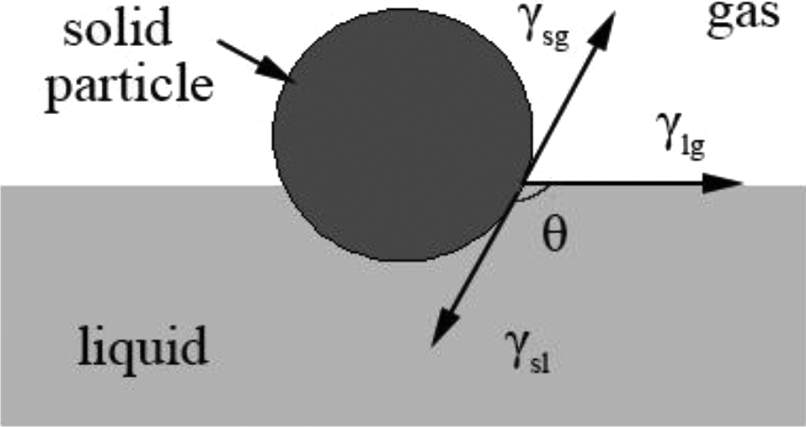
Schematic diagram showing contact angle formed between solid, liquid and gas phases; γsl, γsg and γlg are interracial energies between solid and liquid, solid and gas, and liquid and gas phases respectively
Experimental
Selection and preparation of brazing filler metal
In many kinds of commercial aluminium based brazing filler metal, a series of Al–Si–Mg–Ti is supposed to be the best choice for this research based on the following reasons:
For element Mg, it is an active element to rupture the Al2O3 film on the surface of Al base metal.
For elements Al and Ni, Si and Ni, and Mg and Ni, solid solubility exists, which is shown in Fig. 2b–d respectively.
The function of element Ti in brazing filler metal is the high affinity for SiC ceramic phase and increases the joint strength. The composition of filler metal is Al–12Si–1.5Mg–4Ti.
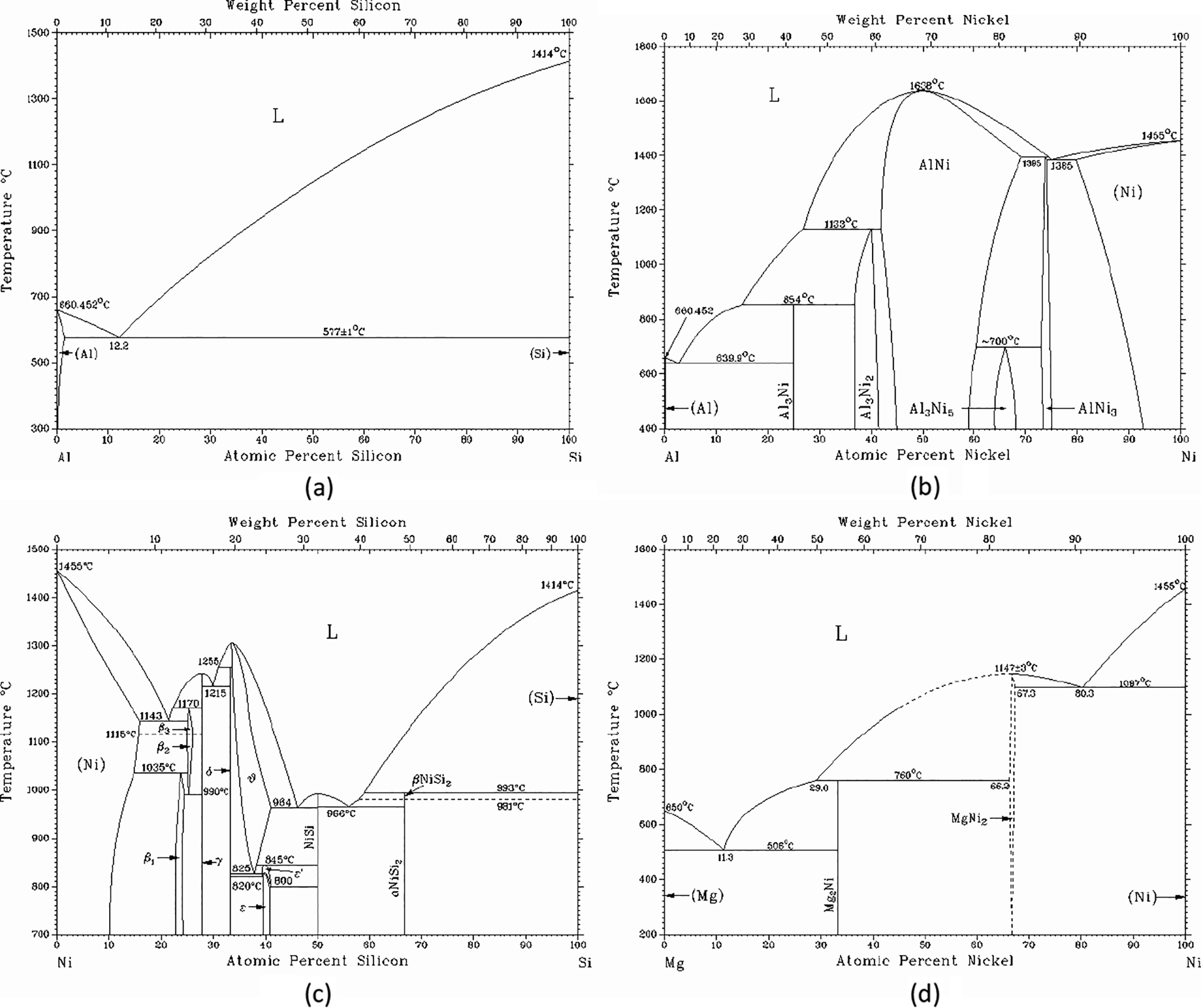
a Al–Si; b Al–Ni; c Ni–Si; d Mg–Ni
The brazing filler metal ingots were obtained by melting four kinds of commercially available blocks of Al-20Si, Al-10Ti and Al-50Mg master alloy, and pure Al in a graphite crucible using high frequency induction heating under the protection of argon (in Fig. 3), then pouring the liquid melt into a steel cylindrical mould, with φ25 mm, and then furnace cooling to room temperature in argon atmosphere to obtain the ingot (in Fig. 4a). The foil was processed by strip cast and was 50–60 μm thick (in Fig. 4b).
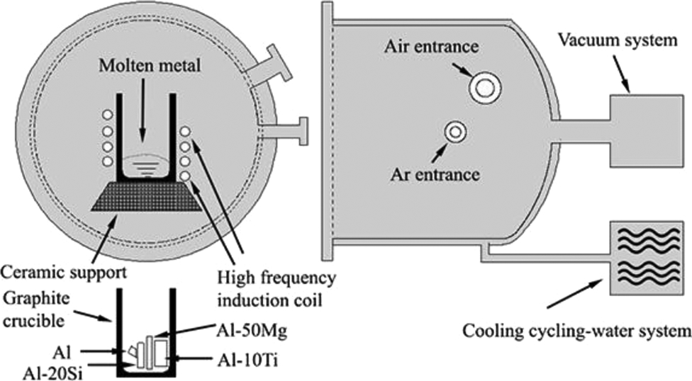
Schematic of apparatus used for melting alloys
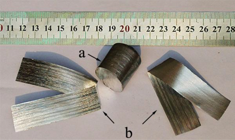
Appearances of Al–12Si–1·5Mg–4Ti ingot (100 g) solidified in steel mould, Al–12Si–1·5Mg–4Ti foil obtained by rapid solidification process, and bended Al–12Si–1·5Mg–4Ti foil
Preparation and surface metallisation of SiCp/6063Al composite
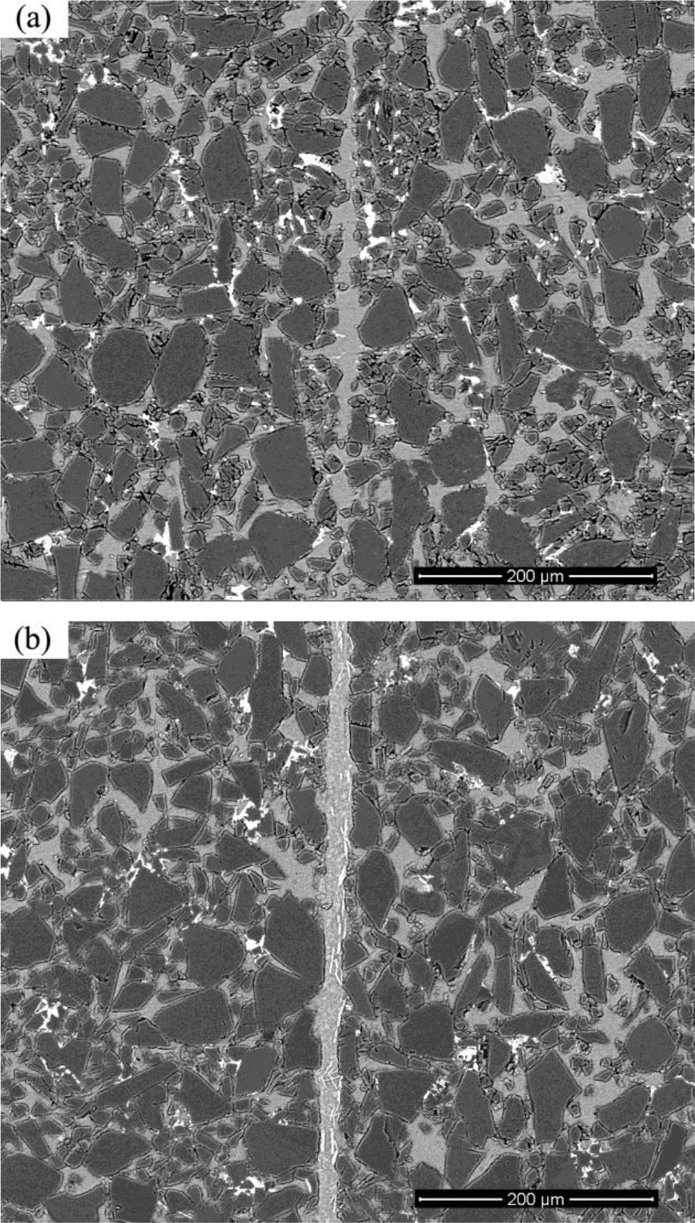
The 20 and 60 vol.-% SiCp/6063Al composites were investigated as base materials, and their specimens were cut into 20 mm × 10 mm × 2 mm strips by NC electric spark line cutting and diamond wire saw (STX-60) respectively. Figure 5a and b shows their microstructures, and the nominal composition of 6063Al is given in Table 1. Owing to SiC covering more than half of the whole surface, electroless Ni plating was applied to improve the wettability of 60 vol.-% SiCp/Al composite, as shown in Fig. 6b. Ni film increases the overall surface energy of the particulates by altering the nature of the interface from metal–ceramic to metal–metal. In order to assess the interfacial adhesion between the nickel coatings and the substrate, a scratch test instrument (WS-2005) was used.
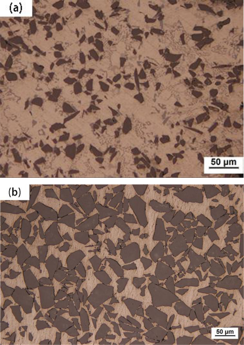
a 20 vol.-%; b 60 vol.-%
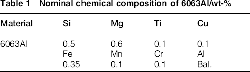
Nominal chemical composition of 6063Al/wt-%

Photomacrographs of base material a before electroless Ni plating and b after electroless Ni plating
Vacuum brazing and performance test of brazed joints
There are two kinds of aluminium based filler metals in the form of the 55–60 μm thick foil with a composition of Al–Si–Mg and Al–Si–Mg–Ti. In addition, a specific jig was used. 16 The assembly of the specimen is shown in Fig. 7. After all samples consisting of the composites and solder alloy are assembled, the brazing process was carried out in a vacuum brazing furnace with temperature of 580°C and a heating rate of 20°C min− 1, kept for 30 min before heating was stopped, and then cooled down to 180°C inside the furnace before taking them out. The shear strength of the single lap joint (Fig. 7) was measured using a special jig, which is made of 40Cr steel (Fig. 8), and the test was performed with a constant rate of 0.2 mm min− 1 at room temperature using an electronic universal testing machine (IIC-MST-100). For reliable results, six samples, made in identical conditions, were tested in each case.
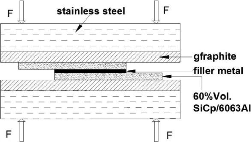
Assembly of soldered specimen of SiCp/6063Al composite
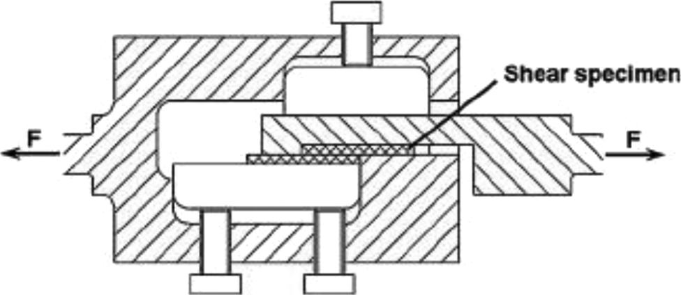
Special jig used for shear testing brazed samples 2
Microscopic examination and the fracture appearance of the brazed joints were performed using scanning electron microscope (SEM, FEI Quanta 200) equipped with an energy dispersive spectrometer (EDS).
Results and discussion
Microstructure and melting characteristics of novel Al–Si–Mg–4Ti filler metal
Figure 4 shows the appearances of Al–12Si–1.5Mg–4Ti ingot (100 g) solidified in a graphite crucible, and its foil was obtained by remelting the ingot followed by rapid solidification process. The obtained Al–12Si–1.5Mg–4Ti brazing foil exhibited favourable ductility that it could bended to 180°C without failure, showing that 4 wt-% Ti addition did not make the new foil brittle.
Figure 9a shows the backscattered electron (BSE) and SEM images of the microstructures of unetched Al–12Si–1.5Mg–4Ti alloy in the form of ingot and foil respectively. In the ingot, most Ti atoms existed as light phase with needle-like shape (length of >100 μm). EDS point analysis results (Table 2) showed that the light needle-like phase contained Ti up to 20 at-% and silicon < 15 at-%, indicating that the light needle-like phase should belong to the ternary compound of Ti(Al1(xSi x )3, which was commonly written as Ti(AlSi)3. 17 From Fig. 9b, the following important information can be found: (i) the morphology of Al–Si–Ti ternary intermetallic compound was changed into fine particle from needle-like shape in ingot, and (ii) numerous Ti atoms could also be present within the supersaturated aluminium matrix with Si atoms; especially, the detected Ti content back of wheel side could reach 1.5 wt.-%, much higher than the solid solubility at room temperature. All of the factors, including refined structure of the foil matrix, 18 the supersaturation state of Ti atoms and little solid solubility of Ti in Al should allow the thermodynamically unstable Ti dissolved in the rapidly solidified foil to react early with alumina film.
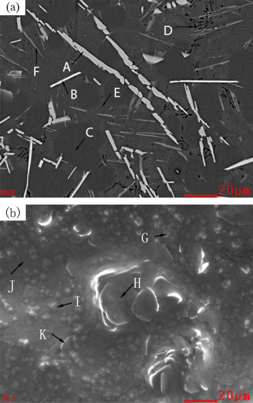
BSE images of solidified ingot of a Al–12Si–1·5Mg–4Ti filler metal and b rapidly solidified Al–12Si–1·5Mg–4Ti foil
Results of EDS point analysis in Fig. 9/at-%
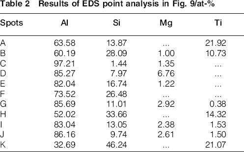
Figure 10 shows the DSC curve of the developed Al–12Si–1.5Mg–4Ti foil in comparison with that of conventional Al–Si–Mg. The conventional Al–Si–Mg foil showed a melting temperature range from 548 to 571°C (Fig. 10a), slightly higher than Al–Si–Mg equilibrium eutectic temperature of 555°C, while the developed Al–12Si–1.5Mg–4Ti showed a melting temperature range from 545 to 569°C, slightly lower than that of Al–Si–Mg foil, which implies that the Al–12Si–1.5Mg–4Ti foil may be promising for brazing the Al-MMCs.
DSC curves of a Al–Si–Mg foil and b developed Al–12Si–1·5Mg–4Ti foil
Electroless Ni plating
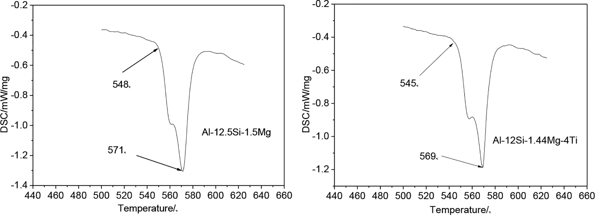
In order to improve the brazed joint's property of the SiCp/Al composites with 60–70 vol.-% non-conducting SiC particles, nickel–phosphorous alloy is deposited on its surface by electroless plating without use of palladium catalyst. Figure 11a shows the surface morphology of the coatings. It can be found that Ni particle existed mainly in the way of clusters, and they give hemispheric grains. 19 Simultaneously, the coated layer grows laterally and vertically, which results in a continuous and dense coated metal layer on the substrate. This behaviour is in accordance with Kong et al. 20 We used a scratch tester (WS-2005) to assess the interfacial adhesion between the nickel coatings and the substrate by an initial load of 0.05 N, up to a maximum load of 100 N and loading rate of 20 N min− 1 at a stable speed of 1 mm min− 1. Figure 11b shows four 5 mm long and crossed scratches in one single specimen and examined microscopically to estimate the load where the coating peeled off rather than removed completely from the substrate channel, seen from Fig. 11c. Even after testing up to 100 N, the coating is not severely damaged as can be seen in Fig. 11d. It can be seen that the failure is cohesive instead of adhesive, and the failure is within the coating itself rather than in the interface between the coating and the substrate. 21
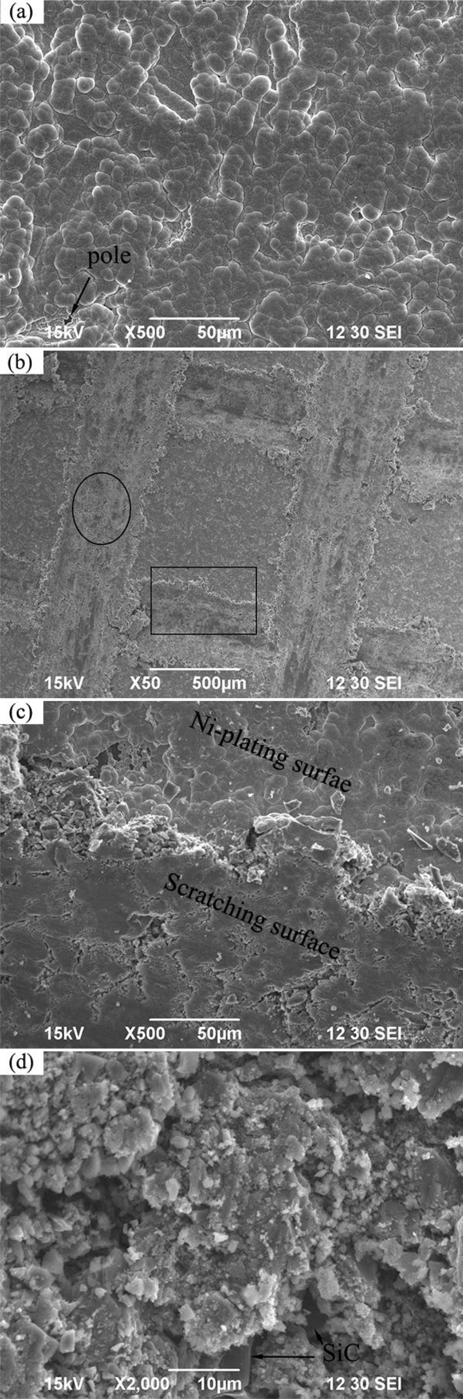
a appearance of Ni film via SEM b scratch; c magnification of rectangular region marked in b; d magnification of elliptical region marked in b
Microstructure and property analysis of joint
Shear strength
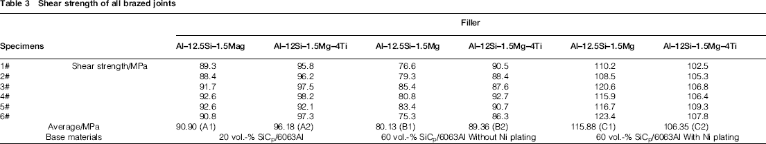
After the brazing process, the shearing test of each joint was carried out using an electronic universal testing machine (IIC-MST-100), and results can be seen from Table 3. Figure 12 shows the average shear strength with different filler foils immediately. The results show that the Al–Si–Mg filler metal with addition of 4 wt-% Ti could enhance the shear strength of brazed joints in varying degree, and there are quite differences for the three base materials. Both filler foils have a better wettability to the SiCp/6063Al composites with low volume fraction (20 vol.-%) than that with high volume fraction (60 vol.-%), so its average shear strength is ∼7–13% higher. However, the wettability could be improved largely after electroless nickel plating for the 60 vol.-% SiCp/6063Al composites because of alteration of the nature of the interface between the filler metal and the SiC ceramic particle from metal–ceramic to metal–metal, and the shear strength can reach to the top, 123.4 MPa, increasing 44% than that without Ni plating.
Shear strength of all brazed joints
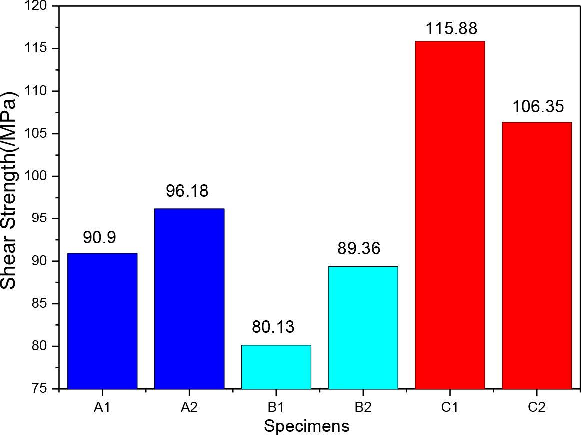
Average shear strength of brazed joints
20 vol.-% SiCp/6063Al
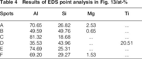
Figure 13 illustrates the microstructure of brazed joint for 20 vol.-% SiCp/Al composites. The brazing seam, ∼35 μm thick, can be seen between the composites. Whether the Al–Si–Mg filler contains Ti element or not, the two molten fillers both compact with the composite tightly, and there are few fractures or holes in the seam at all, as shown in Fig. 13a and c, especially at the interface between filler and composites. The magnified scanning interfaces of the brazing seam, the filler metal and the composites are shown in Fig. 13b and d. The figures indicate that the compact joining is formed in the joint probably because of mutual diffusion of the filler metal and aluminium base composites during the heat preservation at high temperature. From the SEM in Fig. 13d and the EDS point analysis in Table 4, many needle-like phases, probably AlTi3 or Ti(AlSi)3 intermetallic, existed in the inner of the seam after the brazing process, which can enhance the shear strength as the function of SiC in the Al base MMC, while some little SiC particles that cling to the surface of composites were packed into the seam by the molten filler metal with a constant pressure and increased the shear strength as well. However, using Al–Si–Mg foil as filler metal, the connection with the composites just relies on the mutual diffusion of Al base alloy and filler metal, probably forming solid or compound in the whole seam and there is not any SiC particles appearing in the inner of the seam; thus, it could not form a composite brazed joint in the final. As a result, lower shear strength was achieved than that using Al–12Si–1.5Mg–4Ti foil as filler metal.
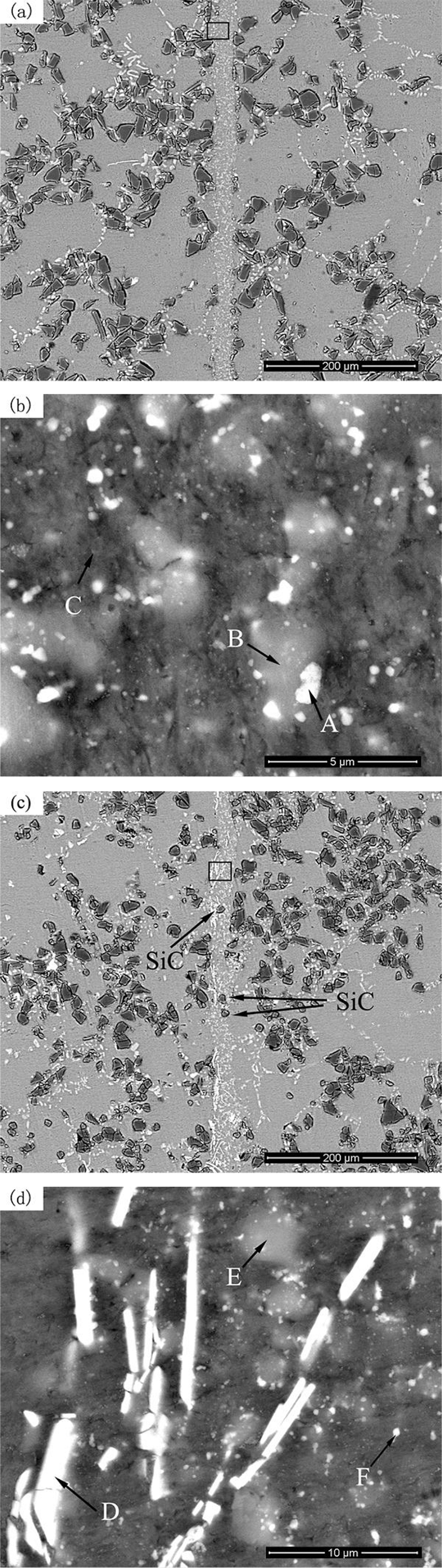
BSE images of brazed joints of 20% SiCp/Al composites: a with Al–12·5Si–1·5Mg solder; b magnification of region marked in a; c with Al–12Si–1·5Mg–4Ti solder; d magnification of region marked in c
Results of EDS point analysis in Fig. 13/at-%
60 vol.-% SiCp/6063Al without electroless Ni plating
In Fig. 5b, optical microscopy of the as received composites showed the presence of bonding between the SiC particles with irregular shape and the aluminium alloy matrix.22, 23 The composites with high volume fraction of SiC reinforced particles mainly consist of very large SiC particles and some much smaller ones, which present higher specific strength and lower coefficient of thermal expansion that composites using single size of SiC particles. 23 From the BSE images, in Fig. 14, the composites compact with the filler metals closely and there were no welding defects. According to Wu et al., 24 the segregation of a few liquid Ti atoms toward the ceramic reinforcement surface and superficial reaction to form an isolated and very thin multielement oxide layer around partial ceramic reinforcement surface could improve the wettability at the R/M interfaces. For the width of the brazed joints, the seam is a bit wider using Al–12Si–1.5Mg–4Ti as filler metal than using the other filler with the same thickness because of high temperature strengthening phases [AlTi3 or Ti(AlSi)3] as framework, blocking the mutual dissolution and diffusion between the molten filler metal and aluminium alloy matrix efficiently. However, if there is no any large strengthening phase forming through the solidification of the seam, the seam will become narrow and thin with a constant pressure by jig after the whole brazing process (Fig. 14a).
a with Al–12·5Si–1·5Mg filler; b with Al–12Si–1·5Mg–4Ti filler
In addition, a few little sizes of SiC particles were packed into the seam, which is beneficial to the combination. If SiC particles occurred in the form of segregation, it would cause high stress concentration and have the potential risk of fracture. 25 When outside surroundings changed, this region, especially the sharp corner of SiC, was more sensitive and easy to generate microcracks propagated quickly, 23 rupture would appear in the final, and the brazed joint was damaged. Just as the results of Table 3 and Fig. 12, this paper accounts for that the shear strength of the brazed joints is lower than that using filler containing the above mentioned Ti element.
60 vol.-% SiCp/6063Al after electroless Ni plating
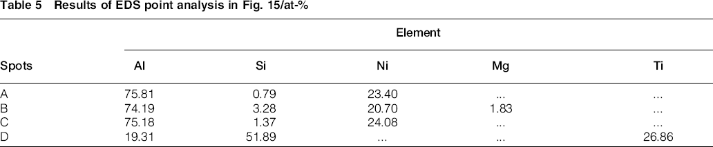
Figure 15 illustrates the microstructure of the brazed joints by EDS analysis. It can be seen from Fig. 15a and b that no detectable defects could be discovered in the seam, and the interfaces between filler and Ni film are considered as superior brazing joints, but clearly show that many white phases existed in the seam and the Al alloy matrix nearby the seam as well. Table 5 shows the results of EDS and indicates that these phases mainly contain Al and Ni elements (see results of spots A and B), which attributes to pure nickel having higher diffusion coefficient and participating metallurgical reaction with Al–Si alloy efficiently during the heat preservation under high temperature of 580°C.
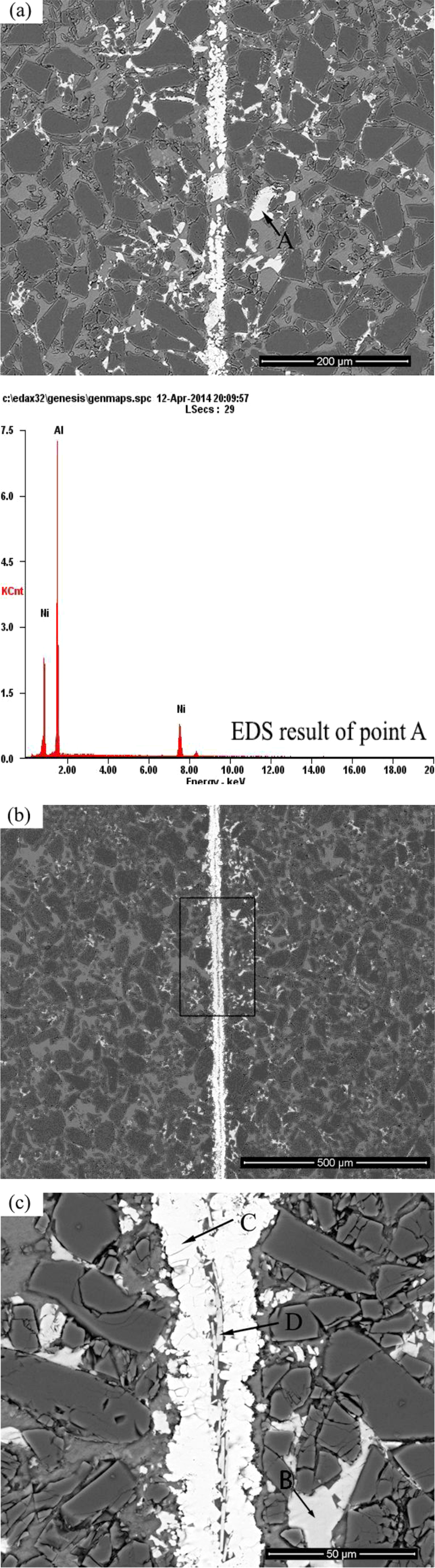
a with Al–12·5Si–1·5Mg filler; b with Al–12Si–1·5Mg–4Ti filler; c magnification of region marked in b
Results of EDS point analysis in Fig. 15/at-%
Additionally, Ni film is just as a bridge conveying elements mutually, such as Al, Ni, Si and other elements, in filler and composite forming solid solution or compound (Al3Ni), and disappeared eventually for ∼30 min soaking time later. The brazed joints can be clearly differentiated from others. If the filler contains the active Ti, AlTi3 or Ti(AlSi)3, those high temperature strengthening phases are hard to dissolve into the liquid filler metal and would reduce the chance of metallurgical reaction between Ni and Si. From Fig. 15c, the magnification of the rectangle region marked in Fig. 15b holes emerged because Ni reacting with Al and Si elements around the strengthening phases formed high stress and damaged the combination, which decreases the joint strength and dissatisfies the high air tightness of electronic packaging.
Fracture appearance analysis of joints
Fracture presents diversiform appearance with different composites and filler metals. The active filler metal containing an active element Ti is mainly discussed in this paper, as shown in Fig. 16. For the 20 vol.-% SiCp/Al composite, the brazed joints achieved a high shear strength and its fracture in Fig. 16a is cleavage. As seen from Fig. 16b, enormous shear lips are probable from the base or filler metal, but no SiC particles existed in the fracture, demonstrating that the ductile fracture is in the filler metal rather than in the base material.
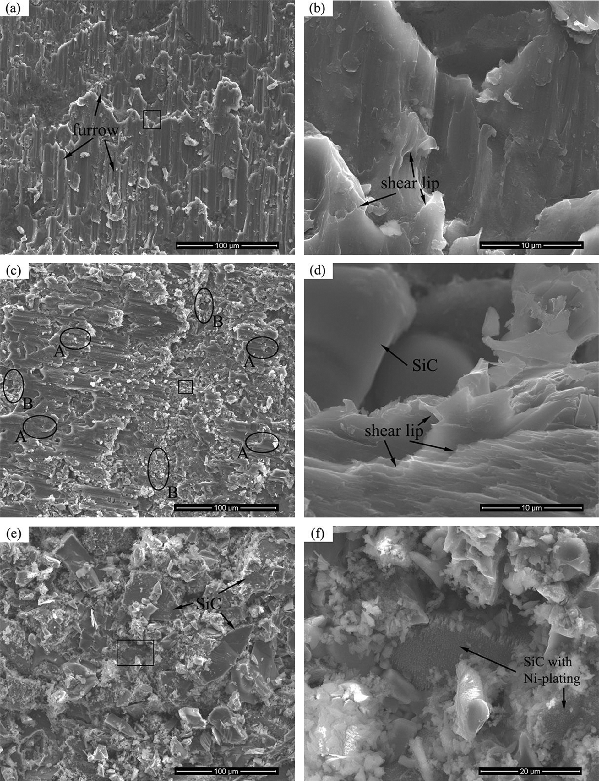
a 20 vol.-% SiCp/6063Al; b magnification of region marked in a; c 60 vol.-% SiCp/6063Al before electroless Ni plating; d magnification of region marked in c; e 60 vol.-% SiCp/6063Al after electroless Ni plating; f magnification of region marked in e
For the 60 vol.-% SiCp/Al composite without electroless Ni plating, the fracture in Fig. 16c is quasi-cleavage and its fracture is composite. One (ellipse region of A), similar to that in Fig. 16a and b, is ductile fracture happening in the filler metal and Al-base alloy of composite, 26 and the other (ellipse region of B) displays the brittle fracture found on the composite side, where peeling pit can be seen due to falloff of SiC particles from the base material and the remaining SiC particle can be found as well. Figure 16d, shear lip representing ductile fracture, demonstrates that the brazed joint achieves high strength, leading to fracture on the composite side. Meanwhile, SiC reinforced particles are uniformly dispersed in the matrix, and the seam, which can pin up dislocations effectively, in a certain degree, increases the shear strength.
However, after electroless Ni plating, fracture is brittle and could be found on the composite side, adjacent to Ni plated interface (in Fig. 16e). The Ni film reacted with the filler metal and base alloy efficiently during the heat preservation, and then formed AlNi3 or other brittle compounds at the interfaces of SiC/Ni film and Ni/filler metal. In addition, its thermal expansion coefficient presents much difference from SiC at 580°C, which decreased the combination between Ni film and SiC. Although Ni deposited layer compacts with SiC closely before brazing (Fig. 16), SiC/Ni film becomes weak interface after the whole brazing process, and fracture easily happened there. In the magnification picture, as shown in Fig. 16f, there is SiC reinforcing phase with residual Ni film and break off of the base material or the filler metal. Their findings clearly show that break off happens in the composites. Additionally, the regions around the Ti(AlSi)3 phase are the source of fracture (analysis as above in Fig. 15b and c). In other words, the active filler, Al–Si–Mg–4%Ti, is not suitable for vacuum brazing the 60 vol.-% SiCp/Al composite with electroless Ni plating for preservation for 30 min at 580°C.
Conclusions
In the work, aluminium matrix composites with 60 vol.-% SiC particle content were vacuum brazed successfully by holding for 30 min at 580°C. Al–12Si–1.5Mg–4Ti alloy as active filler metal foil was mainly investigated and the following conclusions can be drawn:
Electroless Ni plating could increase the wettability of 60 vol.-% SiC particle reinforced 6063Al matrix composites by altering the nature of the interface from metal–ceramic to metal–metal, and the Ni film compact with SiC particles closely.
For the conventional Al–12.5Si–1.5Mg filler metal foil, the shear strength of brazed joints decreased with increasing volume fraction of SiC particle from 20 to 60%. If Ni plating deposits on the composites with 60 vol.-% SiC content, filler metal will have a good wettability to it and shear strength reached 123.4 MPa.
For the developed Al–12Si–1.5Mg–4Ti active filler foil, Ti(AlSi)3 intermetallic as high temperature strengthening phases in the seam could obviously improve the shear strength without Ni plating. In a word, Al–12Si–1.5Mg–4Ti active filler foil is a promising filler for brazing of aluminium matrix composites with high SiC particle content.
Acknowledgements
This work was financially supported by the National Natural Science Foundation of China (grant no. 51245008) and Innovation Fund for Technology Based Firms of Ministry of Science and Technology of China (grant no. 11C26214105167).