
Abstract
Two high strength Nb/Ti microalloyed S690QL steels were welded with identical filler material, varying welding parameters to obtain three cooling rates: slow, medium and fast cooling. As cooling rate increased, the predominantly acicular ferrite in Nb weld metal (WM) is substituted by bainite, with a consequence of obvious hardness increase, but in Ti WM, no great variation of acicular ferrite at all cooling rates contributed to little increment of hardness. The transition between bainite and acicular ferrite has been analysed from the point view of inclusions characteristics, chemical composition and cooling rate. Excellent Charpy toughness at 233 K was obtained with acicular ferrite as predominantly microstructure. Even with bainite weld of high hardness, the toughness was nearly enough to fulfill the minimal requirements. WM for Ti steel showed to be markedly less sensitive to the variations of cooling rate than that for Nb steel.
Introduction
The economical and environmental benefits from high strength microalloyed steel application depend strongly on the use of high productivity welding process, appropriate filler materials and also final excellent welded structure. Therefore, it is necessary to have a fundamental understanding of the influence from modern welding process on the microstructure change and mechanical properties of high strength microalloyed steel weld metal (WM). 1
With regards to the factors that affect toughness and strength, microstructure is of paramount importance, and the grain size, non-metallic inclusions or solute alloy elements have additional effect. High proportion of AF (acicular ferrite) in WM is one effective way to achieve good combination of strength and toughness due to special characteristics of fine interlocking structure. 2 The nucleation of AF is reported to closely relate with non-metallic inclusions, and such inclusion assisted control becomes one significant technology to improve the properties of welds. 3 Hence, an appropriate level of alloying (especially the Ti and Al),4, 5 and the oxide metallurgy 6 have become useful guidance for the design of filler materials and steel plates. Additionally, to consider WM chemistries, it is reasonable to combine the as deposited part from filler materials with melted base steel especially in the case of high dilution. 7
In spite of chemistries, another factor to control weld microstructure is the matched cooling rate. 8 The sensitivity of WM microstructure to variation in heat input and dilution has been often investigated in submerged arc welding of high strength steels, such as HY80, HSLA80 and ASTM A710 grade A steels.7, 9, 10 Welding methods such as gas metal arc welding or laser welding have been applied for high strength steels in order to reduce heat inputs and increase welding speeds.5, 11, 12 Many studies have developed improved compositions of filler materials and appropriate shielding gas, so that WM enjoys optimal microstructure, high resistance to cracks and good strength and toughness.8, 13–15 Alloying elements that are mostly investigated are Ni, Cr, Cu, Mo, Mn, Al and Ti. 16–18 When modern welding process with high dilution is considered, higher fraction of alloying from base steel should be taken into account in final composition of WM. However, little attention has been paid to evaluate the influence of base steel on the sensitivity of WM to welding parameters in modern welding process.
In the present study, modified spray arc welding is applied for quenched and tempered S690QL steels. Our goal is to investigate the sensitivity of WM to welding parameters in two Nb/Ti microalloyed S690QL steels. To achieve this, different welding parameters were designed to evaluate the variation of microstructure, hardness and Charpy V-notch toughness in WM.
Experimental
The materials investigated in this study are Nb and Ti microalloyed S690QL steels, which have yield strength of minimal 690 MPa. The as received steel plates were in thickness of 6 mm and 6.5 mm respectively. Their chemical compositions are given in Table 1. The welding wire with yield strength of ∼720 MPa was selected to obtain a matched WM, and its chemical composition is present in Table 2.
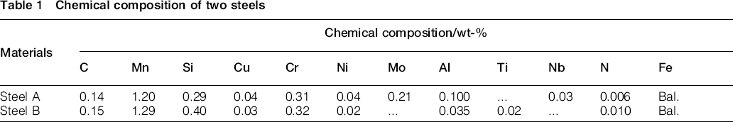
Chemical composition of two steels
Chemical composition of filler material

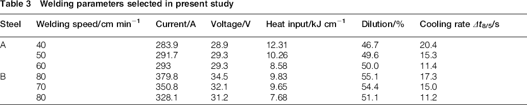
All steel plates were welded using fully automated gas metal arc welding system. Modified spray arc welding process (ForceArc) is applied to conduct the V groove single pass butt welding (30° in angle) under a shielding gas of 82% Ar and 18% CO2. Thermocouples are inserted into weld pool to record the thermal cycle, and measured Δt8/5 time represents cooling rate. Dilution factor can be determined by measuring geometric cross-sectional areas of the deposited filler metal and base materials. 19 Applied welding parameters and cooling rate are listed in Table 3.
Welding parameters selected in present study
Hardness measurements were completed on etched samples using a Vickers indenter with a 10 kgf load for 15 s dwell time. The Charpy toughness was tested at − 40°C using a 300 J Wolpert impact test machine. Three samples were cut from each weld and then prepared into the size of 5 mm × 10 mm × 55 mm. The V-notch is located at the WM centreline, and tests were conducted according to standard DIN EN ISO 148-1:2011. 20
The samples were etched with 2% nital for metallurgical analysis by light optical microscopy (LOM) and by field emission gun scanning electron microscope (FEG-SEM) LEO 1530 VP Gemini operating at 15 kV. A minimum sampling of >4500 inclusions using SEM in backscattered mode was obtained to quantitatively evaluate the inclusion characteristics. Fracture surfaces of Charpy samples were analysed using SEM (Tescan VEGA3). The chemical composition of WM is determined by spark emission spectroscopy.
Results
Hardness
Fig. 1 shows the average hardness of two WMs as a function of heat input. Each value is the average of all hardness points measured within WM. Hardness of WM A increases as heat input decreases. At low heat input, the average hardness is relatively much higher and amounts to ∼350 HV10. Such trend can be explained by the formation of a hard structure in WM A. By contrast, the average hardness in WM B is independent from heat input. The values are almost at the same level of ∼250 HV10. In addition, the scattering band indicates that WM B obtains more homogenous microstructure than WM A at fast or slow cooling.
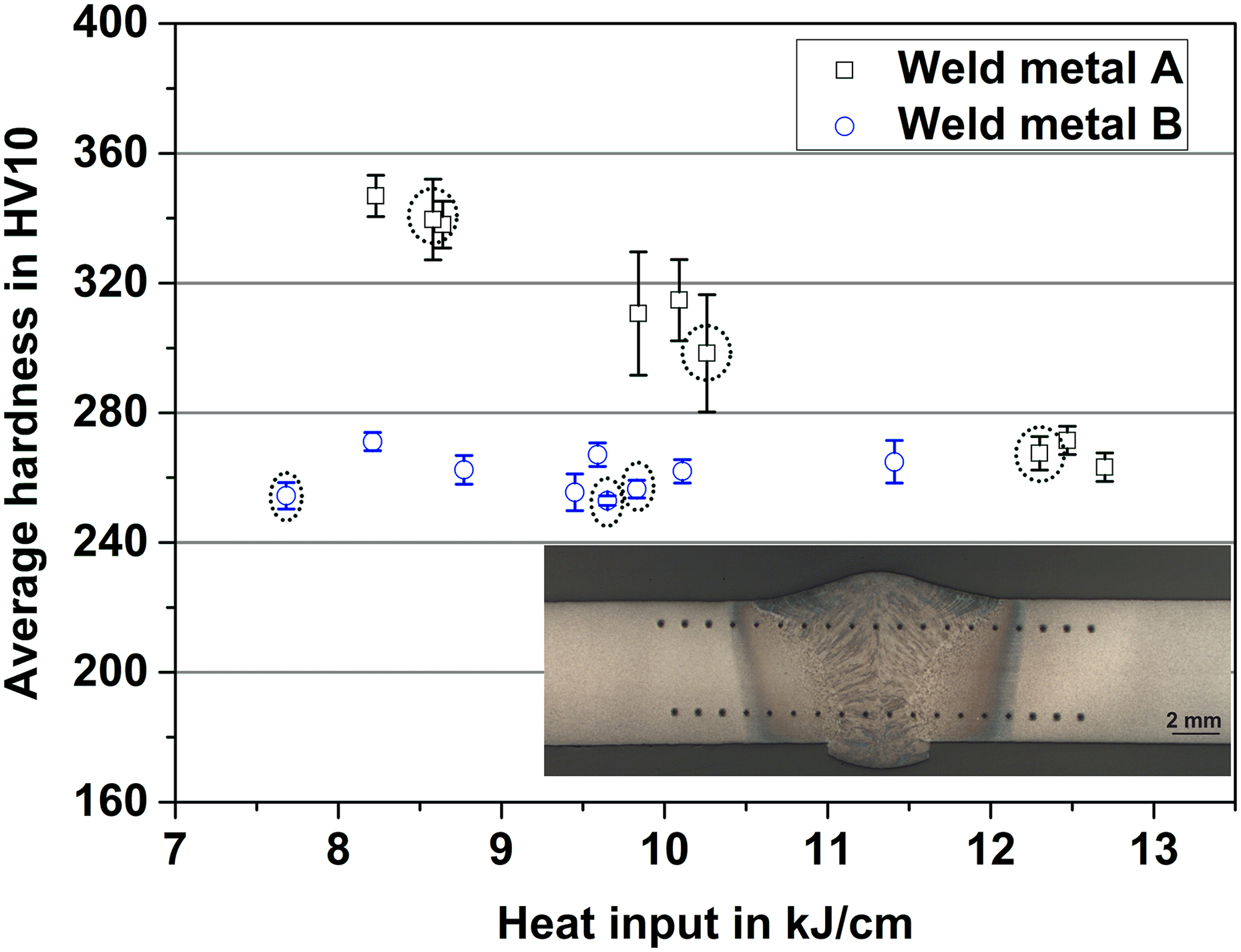
Average hardness of WMs as function of heat inputs; dashed circles are specimens selected for further investigation
The detailed hardness profiles across WM at different cooling rates are displayed in Fig. 2. Of all the WM A, a hardness increase is observed close to FZ (fusion zone). However, WM B exhibits quite small fluctuation of hardness across the whole WM. Hence, it is expected that WM A could probably experience microstructure changes near FZ, where the corresponding hardness raises.
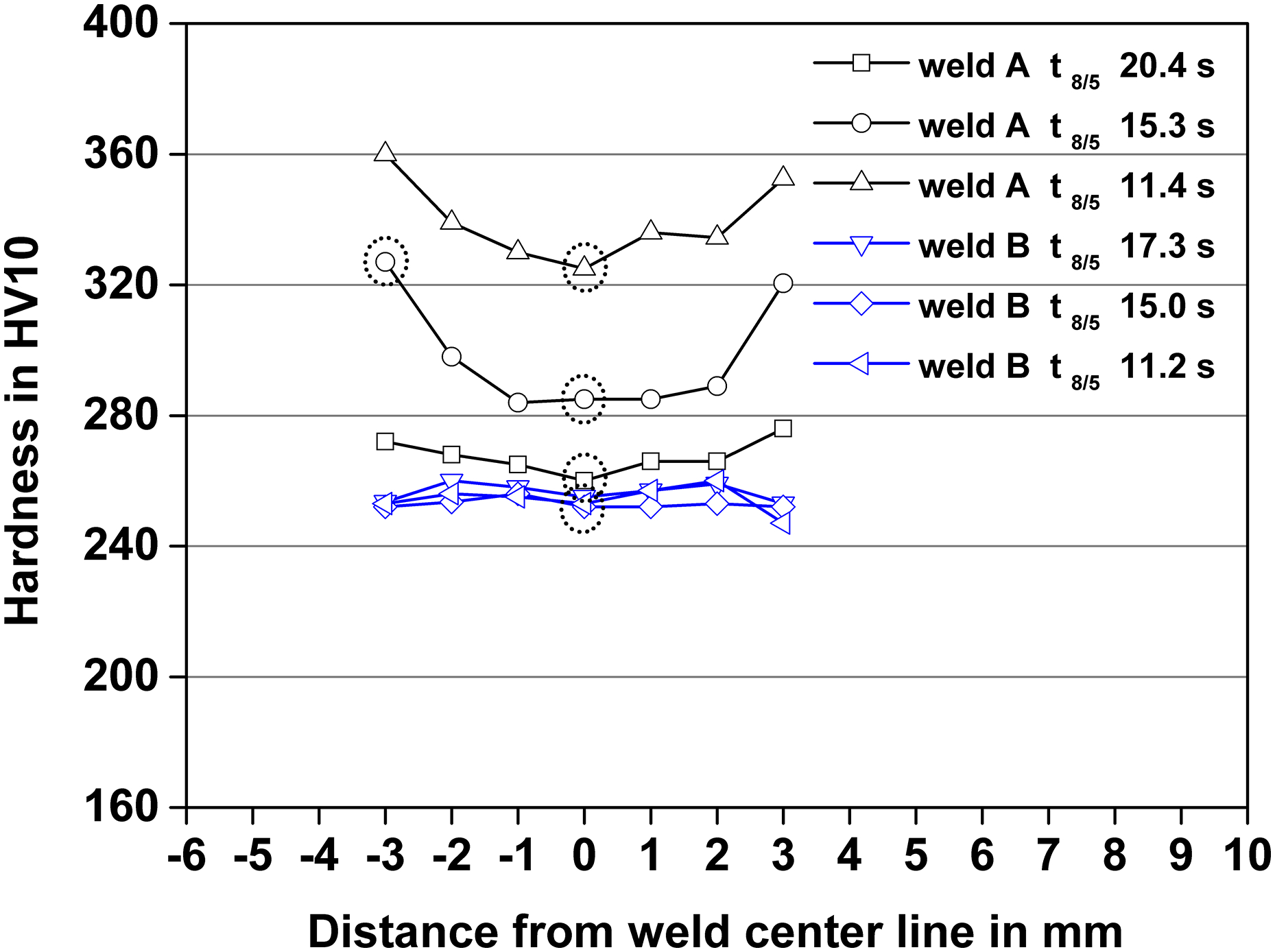
Hardness distribution profile in two WMs at different cooling rates; dashed circles are areas for further microstructural observation
Microstructure
The LOM images revealing microstructure from WM A, as a function of cooling rate, are shown in Fig. 3. At slow cooling rate Δt8/5 20.4 s, predominantly interlocked AF is visible (Fig. 3a), where large inclusions are sometimes observed. As heat input drops to medium level 10.26 kJ cm− 1, this characteristic microstructure is still present in the weld centre (Fig. 3b), but a clear tendency to form much finer ferrite with large aspect ratio is observed. Near FZ, where cooling rate is relatively higher, the microstructure is composed of AF and bainite (Fig. 3c). When cooling rate (Δt8/5 11.4 s) further increases, non-parallel AF is hardly found, and it consists of predominantly bainitic ferrite (Fig. 3d).

a Δt8/5 20.4 s in weld centre; b Δt8/5 15.3 s in weld centre; c near FZ; d Δt8/5 11.4 s in weld centre
Chaotic structure of AF is often observed to intragranularly nucleate on inclusions (Fig. 4 a and b). A great microstructure change occurs near FZ (Fig. 4c), where large amount of bainitic ferrites with much finer needle-like carbides inside are obtained. At fast cooling rate Δt8/5 11.4 s, typical parallel bainitic ferrite with small light coloured carbides inside is mainly formed. Some inclusions are found to be contained within bainitic ferrite rather than potential to stimulate AF nucleation, as indicated by arrows in Fig. 4c and d. Hence, Fig. 4a–d shows that in AF structure, the inclusions often appear to nucleate ferrite, while this facilitation effect is ineffective in bainitic ferrite.
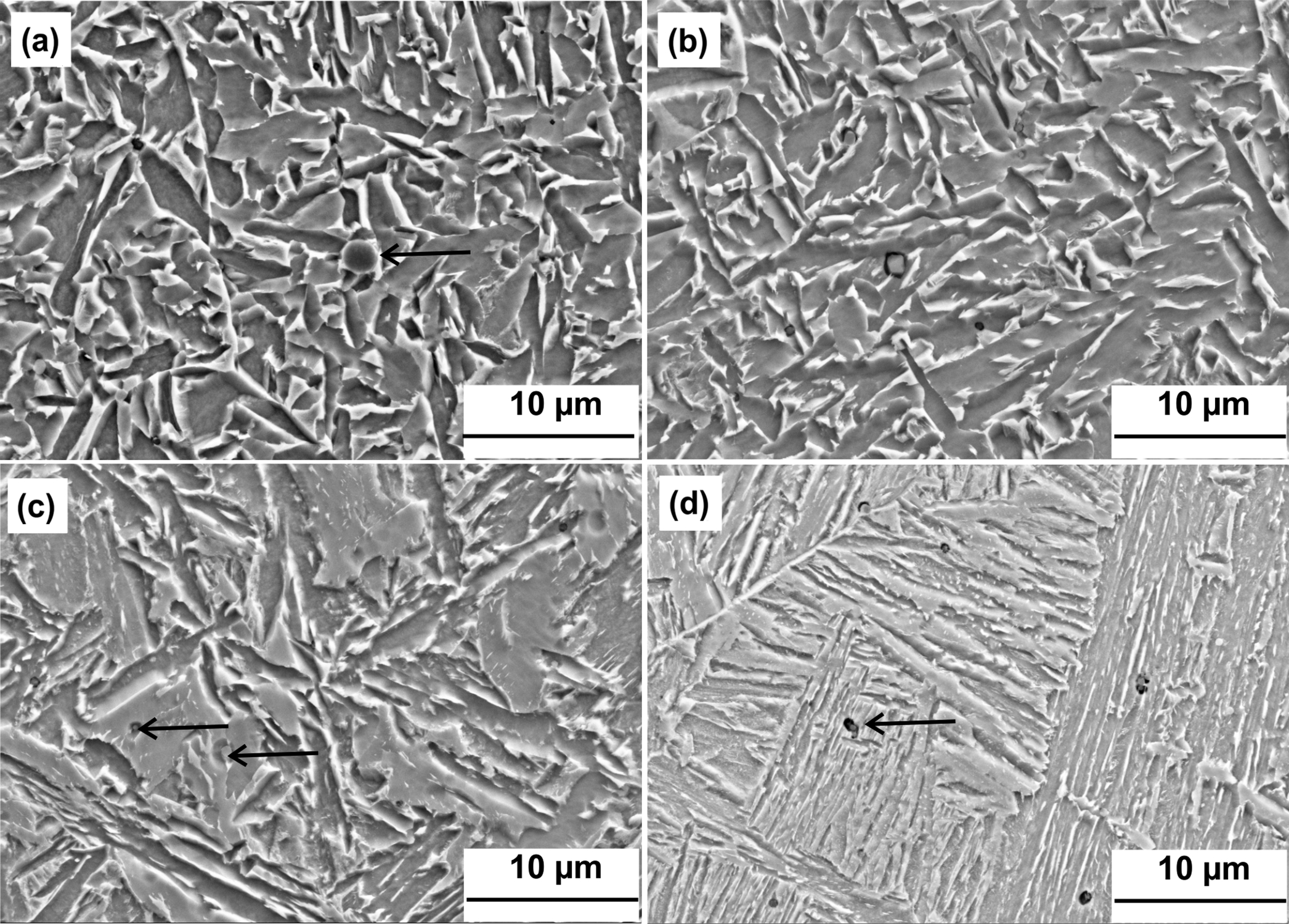
a Δt8/5 20.4 s; b Δt8/5 15.3 s in weld centre; c near FZ; d Δt8/5 11.4 s
Weld microstructure from B is not dependable on the cooling rate changes but remains acicular ferrite as dominant structure. This consistent microstructure contributes to corresponding hardness at the same level (Fig. 2). One micrograph example at fast cooling Δt8/5 11.2 s is given in Fig. 5. Typical AF morphology is apparent, which indicates that even at fast cooling such preferable microstructure can form in WM B.
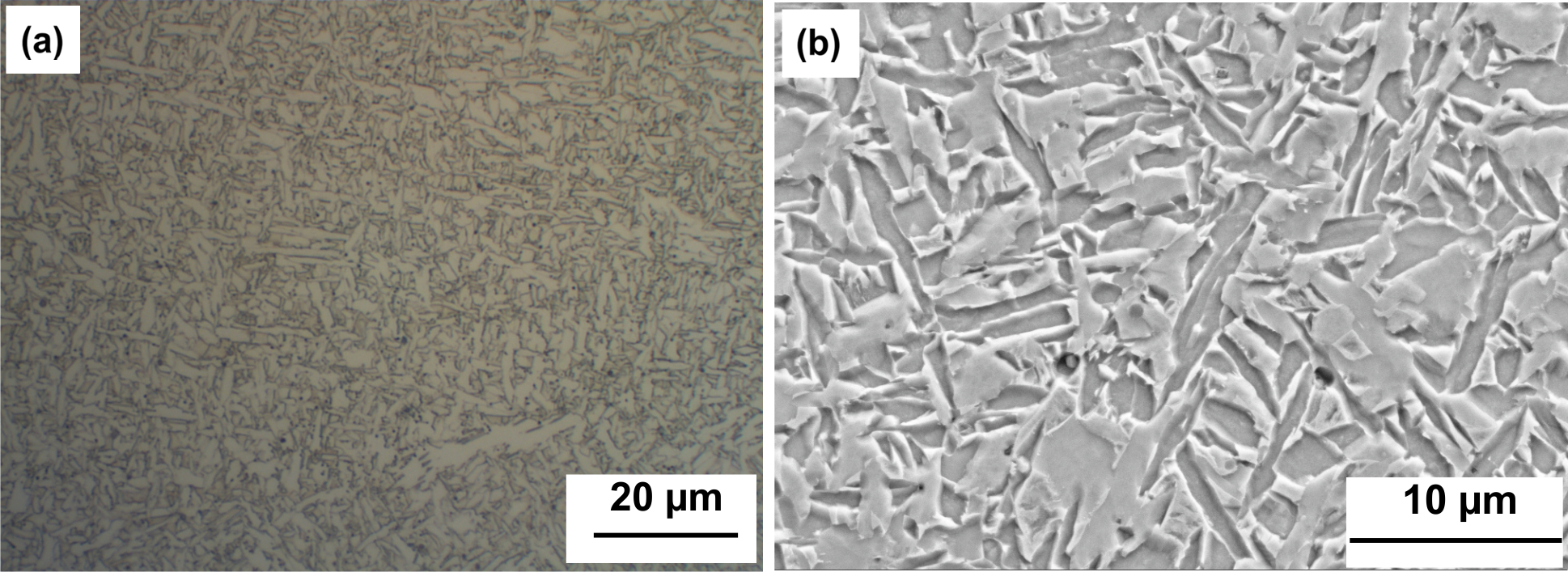
LOM image (a) and FEG-SEM image (b) of WM B at fast cooling rate Δt 8/5 11.2 s in weld centre
Charpy V-notch toughness
Table 4 shows the CVN absorbed energy (J) values at 233 K ( − 40°C). It is noticeable that good agreement between microstructure evolution, hardness and toughness values exists in both two WMs. For WM A, the CVN values show an abrupt fall from slow cooling rate to fast one, which proves that toughness is strongly dependent on the proportion of AF. High fraction of bainite does offer a good explanation for the lower Charpy values. There is no significant difference between main microstructure of WM B, resulting in similar CVN values at all cooling rates. When correlated toughness results with hardness (Fig. 2), it can be confirmed that lower impact values were obtained at higher hardness.
The Charpy V-notch toughness results at 233 K ( − 40°C)
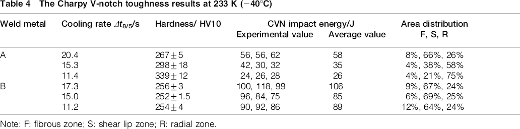
Note: F: fibrous zone; S: shear lip zone; R: radial zone.
Generally, in Charpy specimen, the fracture surface can be divided into three zones: fibrous zone, radial zone and shear lip zone. At first, a ductile crack is initiated at the centre of the notch root after yielding and the fibrous zone is formed. As the crack propagates ahead of the notch, it spreads laterally and propagates through the thickness, resulting in radial zone and shear lip zone formation at the outer surface. 21 It is worth noting that the energy absorbed for radial zone and shear lip zone formation account mostly for the total CVN energy. Figure 6 shows the fracture surfaces of six representative specimens from two WMs. From the overview, different models of failure in radial zones are readily distinguishable even under small magnification. The fraction of shear lip zone can indicate its contribution to final absorbed impact energy, because it is formed by a ductile dimpled mode.
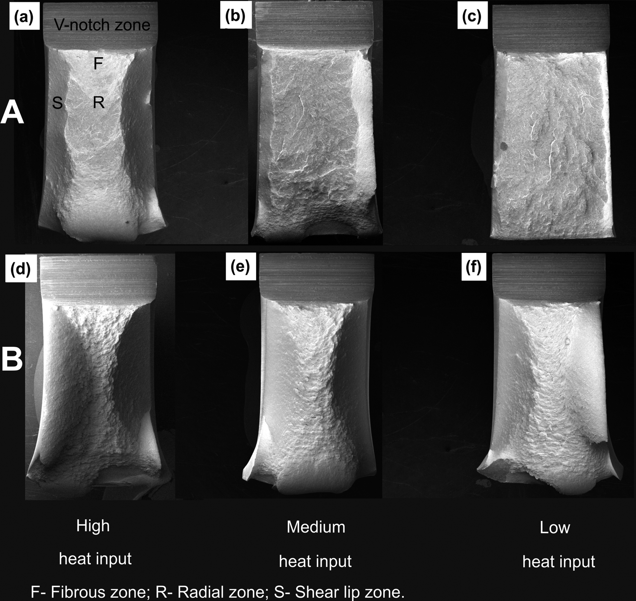
For WMA, a Δt8/5 20.4 s, b Δt8/5 15.3 s and c Δt8/5 11.4 s, and for WM B at cooling rates d Δt8/5 17.3 s, e Δt8/5 15.0 s and f Δt8/5 11.2 s
Fig. 7 shows the fractographs at radial zone. Fracture occurs by a mixed ductile and quasi-cleavage mode in WM A subjected to slow and medium cooling (Fig. 7a and c), whereas at fast cooling it is characterised by a cleavage mode (Fig. 7e). Therefore, as cooling rate increases, cleavage fracture became the prevailing mechanism in WM A. Within quasi-cleavage fracture surface, very small facets are seen to be connected by tear ridges and shallow dimples. Relatively large and elongated facets separated by heavy ridges are present in cleavage fracture (Fig. 7e). Such large cleavage facets also indicate a large bainite packet size in fully bainitic microstructure, as seen in Fig. 4d. It has been proposed that bainite packet size corresponds to the fracture facet and large size accounted for the deterioration in notch toughness. 7 Small inclusions are also observed inside dimples and cleavage facets, and they do not act as the main trigger sites. The features observed in WM B are always fully ductile (Fig. 7b, d and f), where typical small and deep dimples are present. Above all, the fracture mechanism in radial zone combined with shear lip zone fraction is closely correlated with final CVN values.
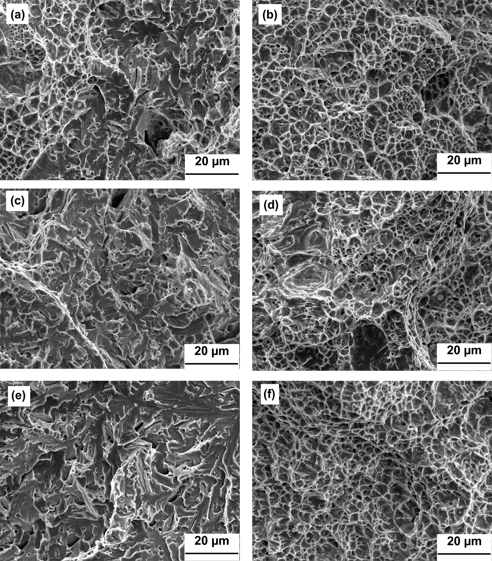
Fractographs in radial zone of two welds at different cooling rates. For WMA A, a Δt8/5 20.4 s, c Δt8/5 11.4 s, and e Δt8/5 15.0 s, and for WMA B, b, Δt8/5 17.3 s, d Δt8/5 15.0 s and f Δt8/5 11.2 s
Discussion
Inspection of Table 4 reveals that welding parameters are observed to be one important variable affecting toughness especially for WM A. Actually, this influence can finally be achieved through influencing the weld microstructure, hardness or chemical composition. Microstructural variation is the most important factor to control toughness since different transformation products possess different inherent fracture resistances. 22 This has been well approved from our results in WM A, where the presence of bainite at fast cooling shows much less tougher than AF with fine, interlocking and tough ferrite plates.
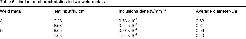
The competition between AF and bainite formation depends on several factors, such as inclusion characteristics, chemical composition, austenite grain size and cooling rate. 23 Table 6 lists the chemical composition of both WMs. Obviously, relatively high Mo, Nb and Al are contained in WM A due to the high dilution from base metal and the other elements are at similar level. The contents of Ti, Al, Si, Mn, O and N are very significant for AF formation because the precipitation interaction between these elements can greatly influence the nucleation.24, 25 Complex oxides are often observed in present WMs, which are rich in Ti, Al, Mn, Si, O or S elements (Fig. 8). Since identical filler material is used, oxides with similar composition are obtained in two WMs. The size distribution and number density are measured from SEM images, and the data are summarised in Fig. 9 and Table 5 respectively. Here, in quantitative analysis data, very fine ( < 0.2 μm) inclusions are excluded. Figure 9 reveals the frequency histogram for size distribution between 0.2 and 2 μm. Table 5 also shows that the number density per unit area is similar in both welds. Above inclusion characteristics suggest that there is no appreciable difference between two WMs. The beneficial effect from inclusions to promote AF has been well approved in WM B. However, even with similar inclusion characteristics, AF is absent in WM A at fast cooling. It is reasonable to assume that combined Mo+Nb has contributed to this microstructure variation but inclusion characteristic had no controlling influence on this variation. Such combination effect of Mo and Nb could be an alternative explanation for promoting bainite formation (Table 6).
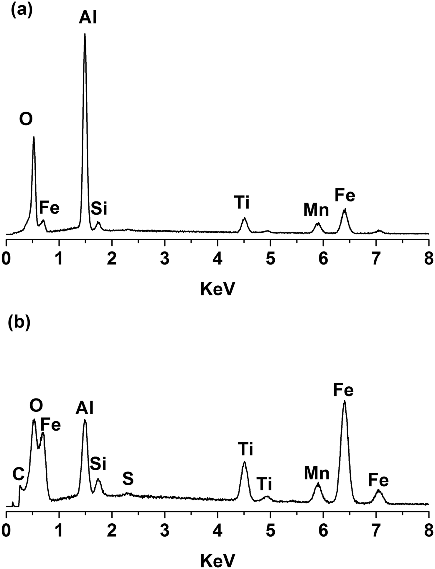
Energy dispersive spectroscopy spectrums of inclusions in WM A at a high heat input and b WM B at low heat input
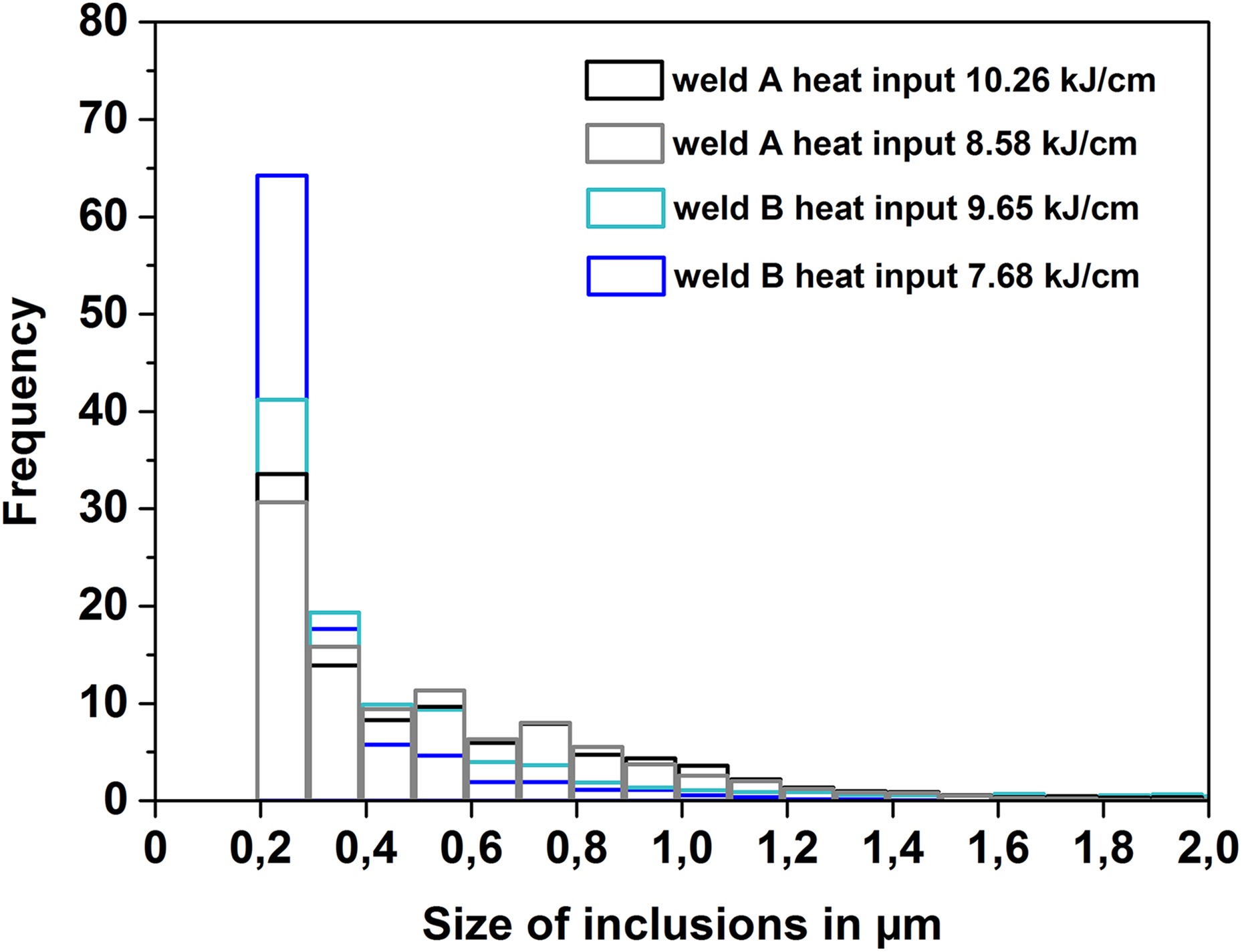
Inclusions size distribution in both welds
Inclusion characteristics in two weld metals
Chemical composition in weld metals/wt-%
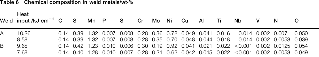
The major role of Mo appears to effectively promote bainite formation instead of AF and further has deleterious effect on toughness, which is closely associated with Mn or Ti contents and cooling rate.1, 26, 27 Evans 28 has concluded that addition of 0.25% Mo can promote AF at 1% Mn concentration and optimised Charpy toughness, but >0.5 % Mo ferrite with second phase will substitute AF. It has been reported that an increase as little as 0.01% Nb was found to induce upper bainite structure in submerged arc weld deposits, but there are still debate in the literature about Nb role on phase formation. 29 The influence of Nb on AF formation depends on the overall hardenability, Nb content and cooling rate. 30 Our observation suggests that the combined Mo+Nb results in a degradation of toughness accompanied by the high fraction of bainite.
Although the same strength grade S690QL steels are welded with identical filler materials, different alloying of base steels can greatly affect weld composition owing to high dilution of modified spray arc welding. In view of microstructural aspects, refined microstructure from AF is desirable for toughness enhancement. The replacement of AF by bainite results in an abrupt fall of toughness from weld A at fast cooling rate. This microstructural and toughness variation is closely correlated with high Mo+Nb level and cooling rate. The present work has provided good guidance on the welding of microalloyed steels based on welding process, metallurgical aspects and mechanical properties.
Conclusions
By modified spray arc welding of two Nb/Ti bearing S690QL steels, the effect of dilution is pronounced to influence the final alloying in welds, causing relatively higher Mo and Nb content in WM A.
High Mo+Nb combined with fast cooling contributed to bainite formation and high hardness value. However, no great change of both hardness and main microstructure with heat inputs occurred to WM B.
AF as predominantly microstructure, with corresponding lower hardness, is a significant characteristic in achieving better Charpy toughness than bainite in WM A at fast cooling.
Ti addition increases the window of allowable cooling rates in WM very significantly, since no appreciable difference happened from the point of microstructure, hardness and toughness. However, addition of Nb+Mo made WM A more sensible to cooling rate.
Acknowledgements
We thank R. S. Neumann, M. Buchheim, S. Brunow and F. T. Boateng from Federal Institute for Materials Research and Testing (Germany) for their kind support. One of the authors (L.Z.) also appreciates the funding support from China Scholarship Council.