
Abstract
Controlling the Fe–Al intermetallic layer thickness along the joint interface has remained a critical challenge in gas metal arc welding of galvanised steel and aluminium alloys. An attempt is presented here to join galvannealed steel and aluminium alloy sheets using a novel gas metal arc welding process that allows controlled short circuiting to reduce the rate of heat input significantly. The real time current and voltage transients during the process are monitored to estimate the rate of heat input and its influence on the formation of intermetallic phases and layer thickness. The results show that the intermetallic layer thickness can be controlled and good joint strengths can be achieved when the rate of heat input remains lesser than 130 J mm− 1 for the typical lap joint configuration considered here.
Introduction
Joining of mixed materials such as aluminium alloys and coated steel sheets has gained significant attention in the automotive industries for the reduction of vehicular body weights. Several processes such as explosive welding, 1 diffusion welding, 2 laser welding 3 and brazing,4–8 friction stir welding, 9 arc welding and brazing10–17 and laser–gas metal arc (GMA) hybrid welding7, 8 are attempted for the joining of aluminium alloy to steel sheets. Explosive welding needs simple joint geometries to control the inherent chemical explosion. Solid state welding such as diffusion bonding needs a long cycle time and is considered unsuitable in typical automotive industries. Compared with the laser welding process, the GMA welding is considered advantageous due to its flexibility for complex joint geometries. However, the joining of aluminium to steel by GMA welding has remained difficult due to the formation of brittle Fe–Al intermetallic (IMC) phases along the joint interface that degrades the joint quality severely.11–18 Experimental studies had indicated that the interfacial IMC layer thickness could be reduced by controlling the rate of heat input.10, 12, 19, 20 The purpose of the present study is to examine a controlled short circuiting GMA welding process that allows significant lowering of the heat input during arcing and metal transfer for the joining of an aluminium alloy and galvannealed steel.
Murakami et al. reported a direct influence of the rate of heat input on the IMC layer thickness in conventional GMA welding of aluminium and steel with a flux cored Al–Si filler wire. 10 Agudo et al. 11 and Zhang et al.12, 18, 19 reported significant increase in the IMC layer thickness with increase in the rate of heat input and attributed it to evaporation of zinc and resulting reduction in wettability of molten aluminium on the steel surface. In GMA welding of AA 5052 and galvanised steel, an Al–Si based filler wire could reduce the IMC layer thickness that was attributed to the formation of Al–Fe–Si phases in preference to Fe–Al phases.14, 17 The interfacial failure of aluminium to steel brazed joints was reported to reduce when the IMC layer thickness could be contained within 4–5 μm.20–22 The above studies have shown the predominant influence of the rate of heat input on the formation of IMC layers in joining of aluminium alloys and steel using arc or laser beam welding processes. However, the role of recent advancements in short circuiting GMA welding processes on the real time current and voltage transients and its effect on the rate of heat input, IMC layer thickness and the resulting joint strength is rarely reported.
The authors present here a detailed experimental study on joining of AA 5052 and galvannealed steel sheets in lap joint configuration with AA 4043 filler wire using an advanced short circuiting GMA welding process. A microprocessor controlled welding power source Alpha Q551 (EWM GmbH make) is used for the experiments. The specific power source allows a fast responsive phasewise controlled short circuiting and reignition of welding arc. 23 The process is referred to as EWM coldArc that facilitates controlled rise and subsequent rapid fall of the short circuiting current just before the detachment of the droplet to facilitate a low current reignition of the welding arc. 23 The variations in the time averaged current during arcing and short circuiting phases as function of wire feedrate and its consequent influence on the final joint qualities are reported. The nature and the extent of the formation of the IMC phases along the joint interface are examined via scanning electron microscopy.
Experimental
Figure 1 schematically shows the weld joint configuration with the workpiece materials confirming to 1.5 mm thick AA 5052 alloy and 1.2 mm thick galvannealed (HIF-GA) steel sheets. The samples are made in lap joint configuration with the aluminium alloy placed on the top and overlapping 15 mm on the galvannealed steel sheets. The electrode wire confirms to AA 4043 of 1.2 mm diameter. The welding torch is set at an angle of 75° in the direction opposite to welding speed. Table 1 depicts the chemical compositions of workpiece and electrode materials. A shielding gas of 100% argon at a flowrate of 15 L min− 1 is used for all the experiments. A PC interface data acquisition system (Graphtec make, model no. GL 900-4) is used for real time monitoring of the current and voltage transients at a simultaneous sampling rate of 0.1 MHz. The thermal cycles are measured in the steel sheet close to the joint interface using K-type thermocouples during actual experiments. Table 2 shows the ranges of the welding conditions that are considered here. The weld dimensions are measured along the transverse cross-section after proper polishing and etching with Keller's reagent. The integrity of the interface bonding was confirmed using liquid dye penetrant test. The Fe–Al IMC layers along the joint interface are characterised using an energy dispersive spectroscope (EDS) attached with a CamScan 3200 scanning electrode microscope (SEM). The phases formed along the joint interface were identified using X-ray diffraction, and the data were collected at a step size of 0.02°. The joint strengths are measured in an INSTRON 3369 universal tensile testing machine at a crosshead speed of 1 mm min− 1.
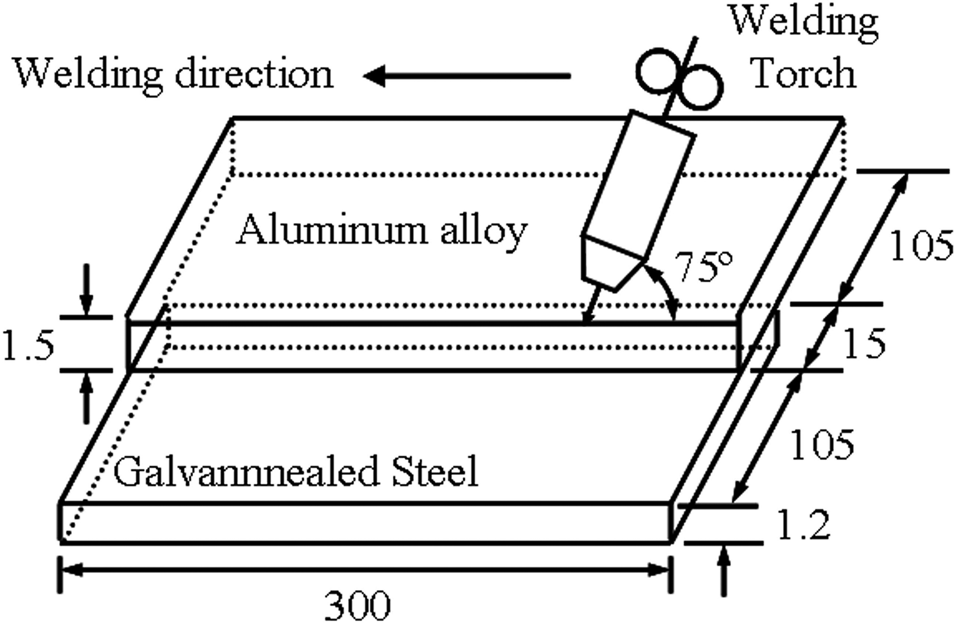
Schematic set-up for EWM coldArc of galvannealed steel and aluminium alloys
Chemical compositions of workpiece materials and filler wire/wt%
Welding conditions used in EWM coldArc welding process
Results and discussion
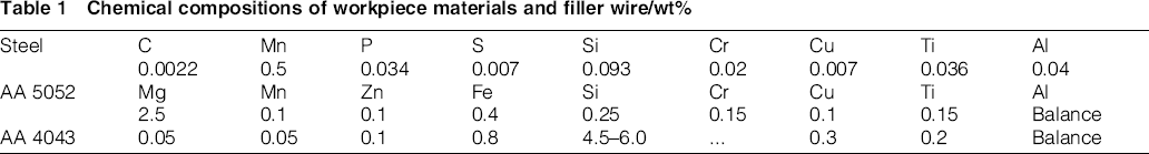
Figure 2a shows the measured current and voltage transients for a wire feedrate of 2.5 m min− 1 and at a welding speed of 5.0 mm s− 1. The current and voltage transients are shown for a shorter duration to maintain clarity with the short circuiting and arcing periods indicated by dashed black lines. The short circuiting period starts with the drop of the arc voltage to a small value (0.4–2.0 V) and a controlled increase in the welding current slope. A high peak current for a very short duration during the short circuiting period facilitates the transfer of liquid metal from electrode to molten weld pool. After a forced reduction of the current to a lower value before detachment of liquid metal, the arcing period starts with rise of the arc voltage to an ignition peak for a short duration. The arc is therefore reignited at a lower current and power in this very sensitive moment of reignition compared to the conventional short circuiting GMA welding processes. 23 Figure 2b–d shows the current and voltage transients at three different wire feedrates of 3.0, 3.5 and 4.0 m min− 1 respectively. A comparison of Fig. 2a–d shows an increase in the short circuiting peak current and arc reignition current from 97 to 140 A and from 39 to 73 A respectively as the wire feedrates increase from 2.5 to 4.0 m min− 1. The time durations of the short circuiting and arcing periods also increase from 7.3 to 7.4 ms and 66.3 to 69.7 ms respectively.
Real time current and voltage transients during EWM coldArc at wire feedrates (m min− 1) of a 2.5, b 3.0, c 3.5 and d 4.0 and at constant welding speed of 5.0 mm s− 1
Figure 3a and b shows a comparison of the time averaged current and arc powers during the short circuiting and the arcing periods at different wire feedrates. The time averaged current IA and arc power PA are estimated as
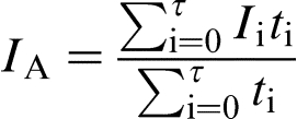
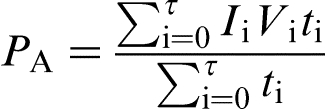
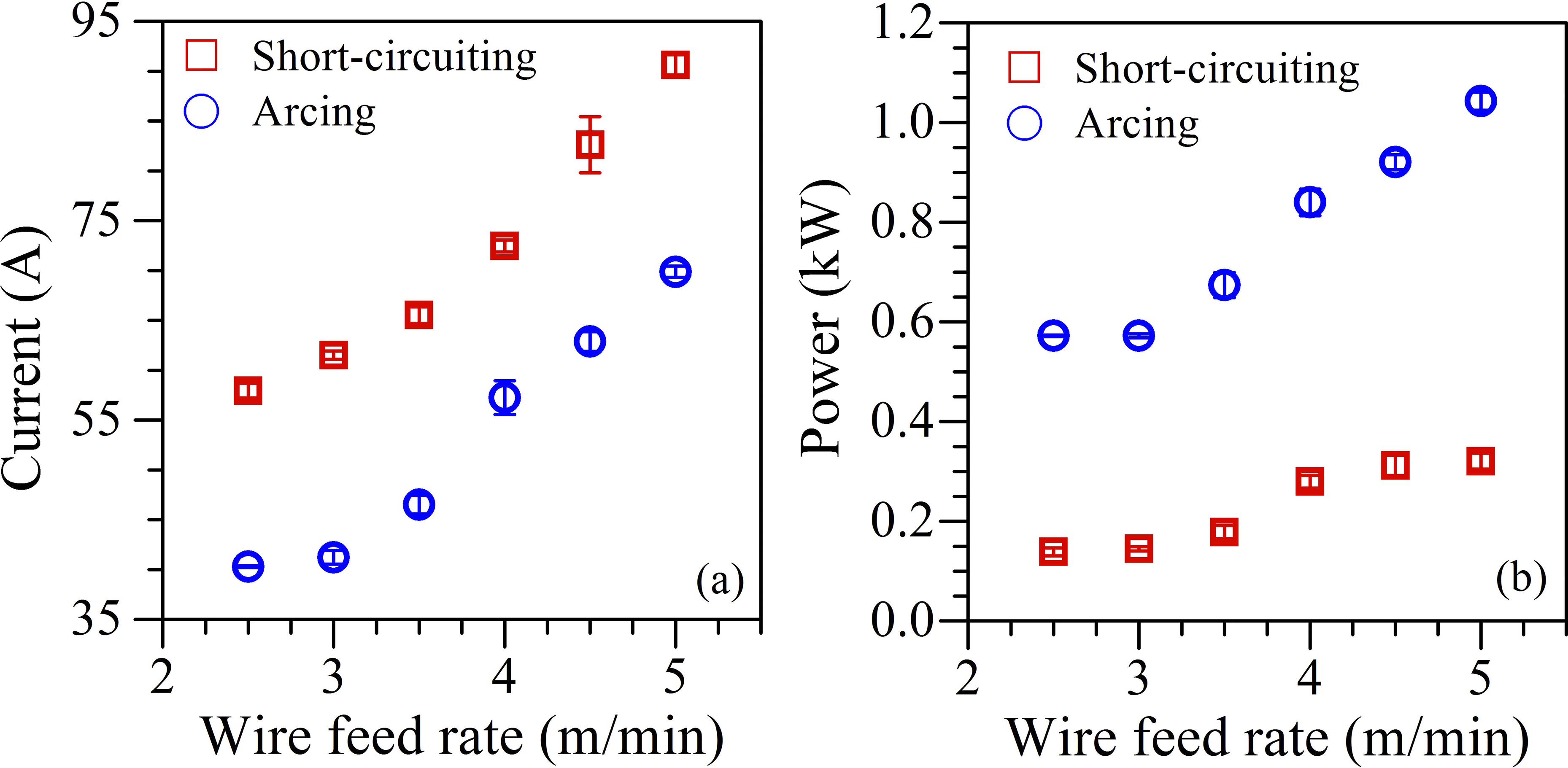
Comparison of time averaged a current and b arc power at different wire feedrates during EWM coldArc at constant welding speed of 5.0 mm s− 1
Figure 4 shows the weld bead profiles of aluminium to galvannealed steel joint at different joining conditions that are considered in the present work. The weld seams achieved at the wire feedrates of 2.5 and 3.0 m min− 1 and welding speed of 5.0 mm s− 1 (Fig. 4a and b) are fairly smooth. Increase in the wire feedrate from 3.5 to 4.0 m min− 1 results in wavy type weld bead (Fig. 4c and d) that is attributed to excess amount of filler wire deposition at higher current. As the welding speed decreases to 3.3 mm s− 1 at a moderate wire feedrate of 3.0 m min− 1, the bead profile remains smooth although the deposition volume per unit length increases (Fig. 4e). At a higher wire feedrate of 4.0 m min− 1 and welding speed of 6.5 mm s− 1, the bead profile becomes erratic (Fig. 4f). The formation of the wavy type and erratic bead shape is mainly attributed to increase in zinc evaporation from the top surface of the steel plate resulting an instability in the arc column and metal transfer. 24 Liquid dye penetrant test has confirmed that all joints are free from defects except the one prepared at the wire feedrate of 4.0 m min− 1 and welding speed of 6.5 mm s− 1 (Fig. 4f) that shows porosity along the interface and in the deposit metal.

a (2·5, 5·0); b (3·0, 5·0); c (3·5, 5·0); d (4·0, 5·0); e (3·0, 3·3); f (4·0, 6·5)
Figure 5a–d shows the micrographs of Fe–Al IMC layers along the aluminium/steel interface at four different joining conditions. The IMC layer thickness in each case is measured at several places along the length of the joint interface and an average value is considered. A comparison of Fig. 5a and b shows that the average interfacial IMC layer thickness increases from 1.62 to 3.14 μm as the wire feedrate increases from 2.5 to 4.0 m min− 1 at a constant welding speed of 5.0 mm s− 1. Similarly, the IMC layer thickness increases from 1.31 to 2.33 μm as the wire feedrate increases from 3.0 to 4.0 m min− 1 at a constant welding speed of 6.5 mm s− 1 (Fig. 5c and d). Increase in the IMC layer thickness with increase in wire feedrate is attributed to the greater rate of heat input. In contrast, a comparison of Fig. 5b and d shows a decrease in the IMC layer thickness with increase in the welding speed that is attributed to the reduction in the rate of heat input at higher welding speed. The IMC layer is oriented towards the weld seam, and its morphology is serrated that increases as the IMC layer thickness increases. Zhang et al. also reported tooth − like IMC structure of 7.0–8.0 μm in GMA welding of wrought aluminium and zinc coated steels.12, 18, 19 The growth of the IMC layer and the change in its morphology with increasing thickness was attributed to the non-uniform diffusion of Fe and Al at the interface. Based on the microstructural observation and phase constitution of IMC layer, it is indicative that the composition of aluminide varies with increased heat input. Furthermore, the serrations in the IMC layer morphology become prominent with more tongue-like features at higher rate of heat input. This is due to the crystalline defects of Fe2Al5 having orthorhombic structures possessing 30% vacancies along the c-axis, the [001] direction. This offers a rapid diffusion path to increase the growth rate of Fe2Al5 resulting in the columnar Fe2Al5.
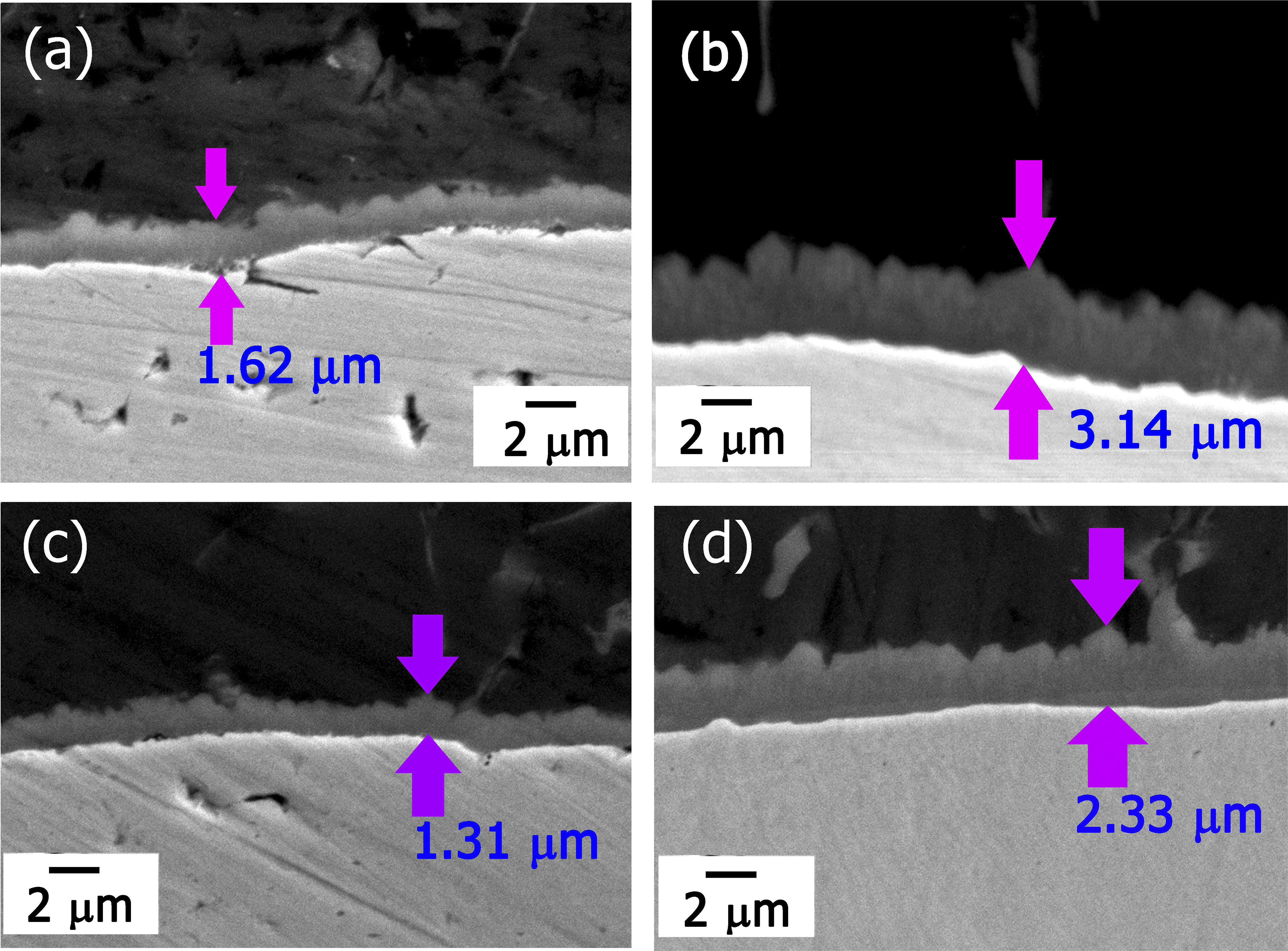
a (2.5, 5.0); b (4.0, 5.0); c (3.0, 6.5); d (4.0, 6.5)
The variation in grey level across the IMC layer from steel to aluminium in Fig. 5 can be attributed to the variation in composition in these layers. To analyse the composition of the IMC layer, energy dispersive X-ray spectrometer (EDS) based point analysis is performed across the interfacial IMC layers for the sample joints. Figure 6a and b shows the elemental concentration in atomic per cent of Fe and Al across the IMC layer that is formed at two different wire feedrates for a constant welding speed. The IMC layer thicknesses corresponding to Fig. 6a and b are 1.62 and 3.14 μm with the corresponding rate of heat inputs as 109.8 and 156.3 J mm− 1. It is evident from Fig. 6 that the composition is uniform when the IMC layer thickness is small, while a large variation in composition occurs as the IMC layer thickness increases. Further, the Al content at the interface of steel and the IMC layer is higher for a thinner layer (Fig. 6a) compared to a thicker layer (Fig. 6b). In thin IMC layer, Al can diffuse very easily and maintain uniformity, while in a thicker IMC layer, the large gradient of Al diffusion can be expected as the welding time is very small. A comparison of the elemental composition analysis from EDS and the Fe–Al phase diagram indicates the formation of Fe2Al5 and FeAl3 for the thinner IMC layer (Figs. 5a and 6a) and FeAl, Fe2Al5 and FeAl3 for the thicker IMC layer (Figs. 5b and 6b).
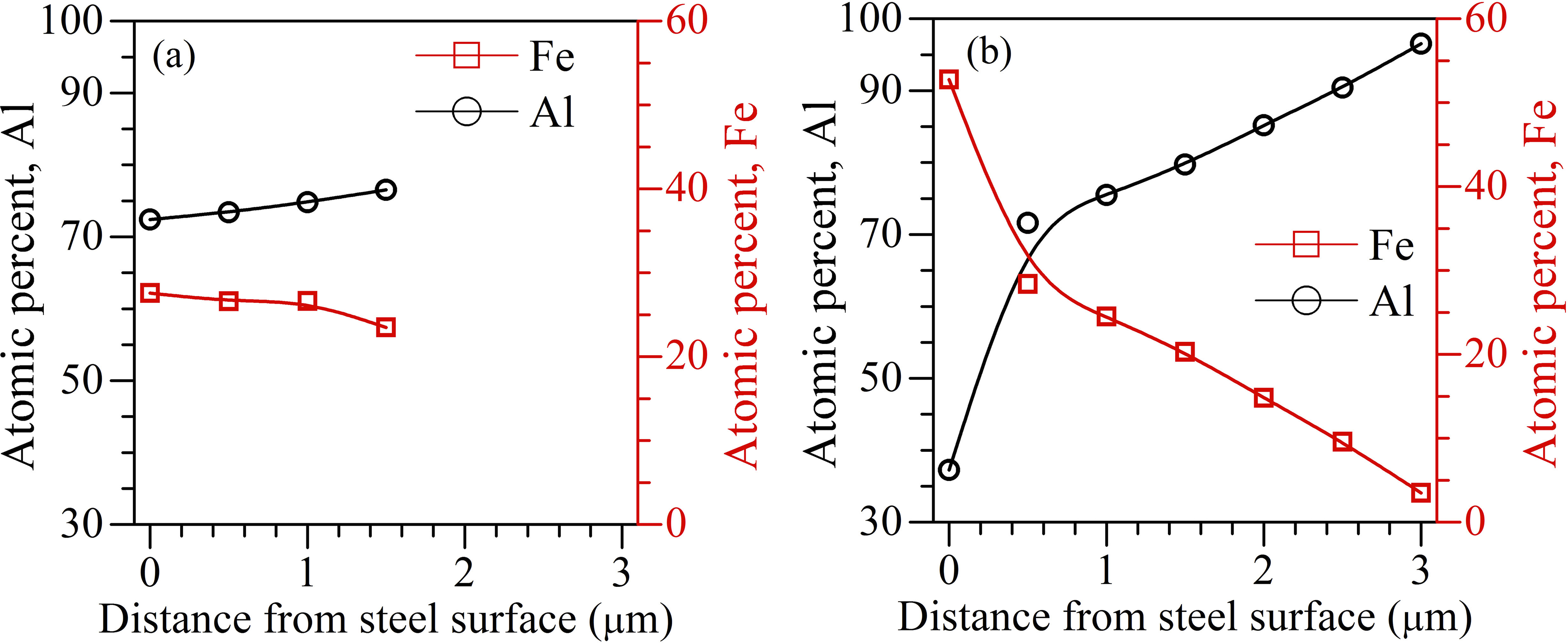
Elemental concentration (in atomic per cent) of Fe and Al across IMC layers, measured from steel surface, in EWM coldArc of AA 5052 and galvannealed steel at two different wire feedrates (m min− 1) of a 2.5 and b 4.0 for constant welding speed of 5.0 mm s− 1
The preferential formation of the Al rich IMC phases at the joint interface can perhaps be explained based on the competitive values of diffusion coefficients between the steel and aluminium. The diffusion coefficient of Fe into Al is 53 × 10− 4 m2s− 1 (520–649°C) and higher than that of Al into Fe, which is 1.8 × 10− 4 m2s− 1 (730–1400°C). 2 Therefore, the diffusion of Fe into Al would be favoured resulting in Al rich IMC phases along the joint interface even at temperature lower then the melting temperature (660°C) of Al. The hold time in the temperature range of 520–649°C will further influence the diffusion induced growth and compositional variations of the interfacial IMC layer.24, 25
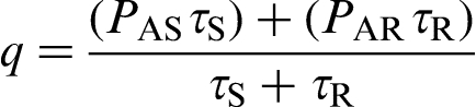
Figure 7 shows the variation of the rate of heat input, the interfacial IMC layer thickness and the corresponding weld joint failure strength as function of wire feedrate and welding speed. A comparison of Fig. 7 shows that increase in the rate of heat input increases the IMC layer thickness, and the corresponding weld joint failure strength decreases. At the lowest welding speed of 3.3 mm s− 1, increase in the wire feedrate from 2.5 to 3.0 m min− 1 leads to an increase in the average interfacial IMC layer thickness from 1.77 to 2.25 μm and the joint strength reduces from 2.8 to 2.0 kN. The higher wire feedrate at the same welding speed of 3.3 mm s− 1 is not attempted further. At the moderate welding speed of 5.0 mm s− 1, increase in the wire feedrate from 2.5 to 4.0 m min− 1 leads to an appreciable increase in the rate of heat input from 109.78 to 156.31 J mm− 1. Consequently, the average interfacial IMC layer increases from 1.62 to 3.14 μm with corresponding decrease in the weld joint failure strength from 4.34 to 2.63 kN. At the highest welding speed of 6.5 mm s− 1, increase in wire feedrate from 3.0 to 4.0 m min− 1 leads to an increase in the rate of heat input from 85.79 to 120.24 J mm− 1. As a result, the IMC layer thickness increases from 1.31 to 2.33 μm, and the weld joint failure strength decreases from 3.32 to 1.87 kN. It is noteworthy that wire feedrate lower than 3.0 m min− 1 at the highest welding speed of 6.5 mm s− 1 could not produce a continuous weld bead.
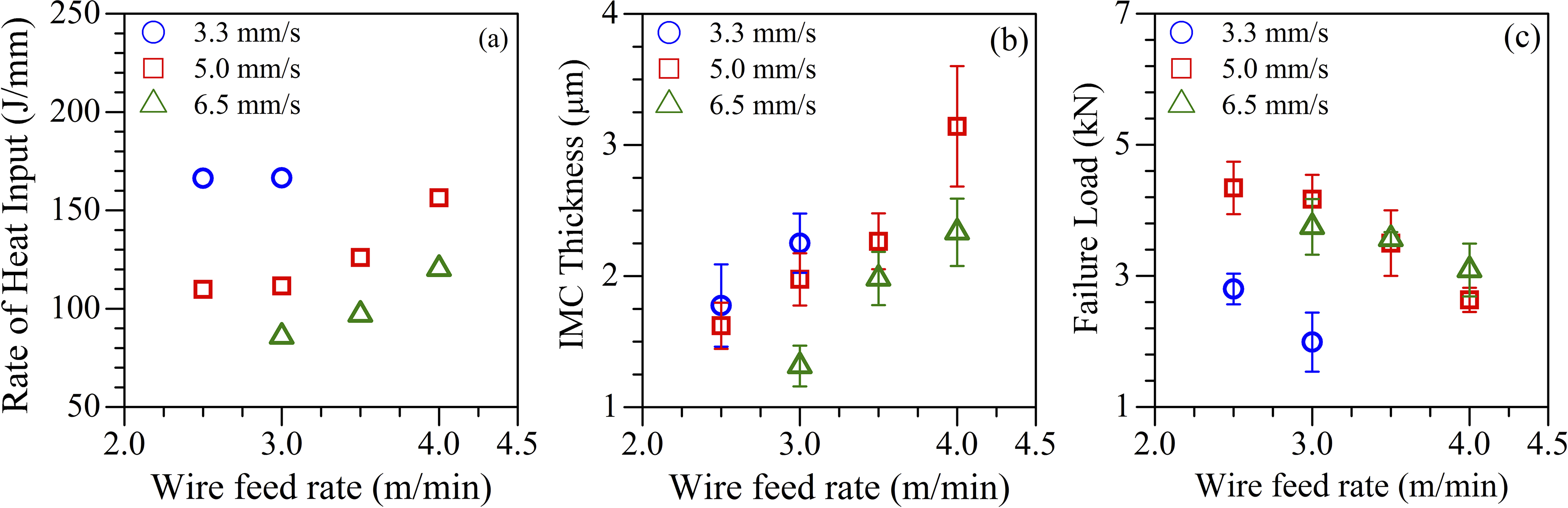
a estimated rate of heat input and measured b intermetallic layer thickness and c weld joint failure strength in lap joints of aluminium alloy and galvannealed steel sheets as function of wire feedrate and welding speed
A comparison of Fig. 7a–c clearly indicates that the nature and the extent of the formation of the IMC layers is influenced by the rate of heat input and the peak values of short circuiting and arcing currents. For example, the average interfacial IMC layer thickness is 3.14 μm at a wire feedrate of 4.0 m min− 1 and welding speed of 5.0 mm s− 1 but reduces to 2.25 μm corresponding to a wire feedrate of 3.0 m min− 1 and welding speed of 3.3 mm s− 1 although the rate of heat input is slightly lower in case of the former welding condition. The increase in peak values of short circuiting and arcing currents at higher wire feedrate thus appears to be critical and requires to be contained.
From the present results and that published in topical literature, it is realised that the strength of interfacial IMC layer in GMA welding of aluminium alloys and steel will depend on the layer composition. The Al rich IMC phases are very hard and brittle, while the Fe rich IMC phases are relatively softer and less brittle, and thus preferred. 25 Figure 5 indicates that the morphology of IMC layer becomes more columnar with increasing heat input, and its composition tends to match to that of Fe2Al5 that is richer with iron than that of FeAl3, which is formed at lower heat input. 26 The columnar structure at the interface is expected to raise stress intensity and reduce failure strength with increase in the IMC layer thickness. A comparison of Figs. 5–7 indicates the permissible range of wire feedrates from 2.5 to 3.5 m min− 1 and corresponding welding speeds of 5.0 to 6.5 mm s− 1 to obtain reasonably good weld bead profile and joint strength for the workpiece materials considered in the present study.
Conclusions
A detailed experimental study on the application of a novel GMA welding process with controlled short circuiting to join AA 5052 to galvannealed steel sheets is presented in this work. Although good joint strengths with smooth bead profiles could be achieved, the results show that the permissible range of wire feedrate and welding speed would remain to be fairly restricted. In particular, the IMC phases such as Fe2Al5 and FeAl3 and the corresponding layer thickness along the joint interface can be contained at relatively lower values of wire feedrate. For the sheet thicknesses considered here, an average interfacial IMC layer thickness of 1.2–1.9 μm resulted in the best weld joint strength.
Acknowledgements
The authors gratefully acknowledge the support of M/s Tata Steel Ltd in providing the automotive grade galvannealed steel sheets for carrying out this study.