
Abstract
Fossil fuel will continue to be the major source of energy for the foreseeable future. To meet the demand for clean and affordable energy, an increase in the operating efficiency of fossil fired power plants is necessary. There are several initiatives worldwide to achieve efficiencies >45% higher heating value (HHV) through an increase in steam temperature (700 to 760°C) and pressure (27.6 to 34.5 MPa). Realising this goal requires materials with excellent creep rupture properties and corrosion resistance at elevated temperatures. In order to accomplish this, three classes of materials have been identified: creep strength enhanced ferritic steels, austenitic stainless steels and nickel base superalloys. Although new alloys have been designed and developed to meet this need, welding can have a significant and often detrimental effect on the required mechanical and corrosion resistant properties. Two previous papers addressed the welding and weldability of ferritic and austenitic stainless steels. Welding and weldability of nickel base alloys will be discussed in a two part paper. In this paper, the primary focus will be on the fundamentals of welding and weldability of Ni base superalloys.
Introduction
An increase in the operating efficiency of the fossil fired power plants is required to meet the increasing global demand for clean and affordable energy and to abide by the regulatory requirements to reduce CO2, SOx and NOx emissions. Coal will continue to be a major source of energy because of its abundance in nature. To achieve higher efficiency, power plants must operate at higher temperatures and pressures. 1 The classification and operating conditions of power plants are discussed in Ref. 2. Efforts are under way in the United States, Europe, Japan, China and India to increase the operating temperature to the range of 700 to 760°C, the pressure to the range of 27.6 to 34.5 MPa and the efficiency to >45% HHV. a Such steam parameters are classified as advanced ultrasupercritical (AUSC) steam conditions. As just one example, the United States Department of Energy and the Ohio Coal Development Office have funded a program to identify or develop materials for the AUSC technology for over a decade.3, 4 The program has set a steam temperature goal of 760°C and a plant efficiency of at least 45% HHV. Similar programs are in place in Europe and Japan.5–7
Realising these goals requires materials with excellent creep rupture properties and corrosion resistance at high temperatures. Identifying or developing new materials that can withstand the operating conditions in an AUSC power plant is a key goal in all of the programs researching AUSC technology. There are a range of challenges that must be met with respect to the components needed to construct an AUSC boiler including the consideration of materials for furnace water walls, pipes and headers, final superheaters and reheaters, boiler tubes, valve bodies and other castings, fittings and others. In the last two decades, significant advances have been made in identifying or developing materials for key AUSC components. Three classes of materials have been identified: (i) 9–12%Cr creep strength enhanced ferritic steels detailed in Ref. 2, (ii) austenitic stainless steels including ‘advanced’ grades as discussed in Ref. 8 and (iii) Ni base superalloys. When used in the appropriate application, these three families of alloys can exhibit excellent creep rupture properties, excellent corrosion and oxidation resistance and good fabricability. The welding and weldability of creep strength enhanced ferritic steels and advanced stainless steels have been discussed in previous papers (Refs. 2 and 8).
Ni base alloys are being considered where temperatures beyond 700°C are reached. The initial materials selection criterion is the same as that for ferritic or austenitic steels, i.e. the temperature to cause rupture in 105 h at 100 MPa. 2 The high cost of Ni and other elements added to form the Ni base superalloys (e.g. Ti, Co, W, Mo) makes the Ni base superalloys very expensive compared to the ferritic or austenitic stainless steels. In the United States, several Ni base superalloys are being considered for application in AUSC power plants: Inconel 740/740H, Haynes 282, Haynes 230, alloy 617 (also known as 617B or CCA617), HR6W and Nimonic 263. Of these alloys, the gamma prime strengthened Haynes 282 and Inconel 740/740H are the strongest candidate materials in the construction of heavy wall components expected to operate at temperatures approaching or exceeding 760°C. 9 The current papers are divided into two parts that describe metallurgy, welding and weldability of candidate Ni base superalloys, including welding processes, filler metals, weld defects, welding dissimilar metals and the prognosis for the future. Part I in particular describes the fundamentals of nickel base superalloys for AUSC coal fired power plants. Part II will cover specific weldability information relevant to the key, candidate AUSC Ni base alloys and the high temperature performance of weldments based on a synthesis of the available literature.
Ni base superalloys
Superalloys constitute an important class of high temperature, high strength alloys with excellent creep rupture properties and resistance to corrosion and oxidation. In practice, these superalloys are mostly referred to by their trade names, such as Inconel alloy 740H or Haynes 282. towing to the diversity of alloys and often their proprietary nature, a fully uniform way of classifying these alloys does not exist, 10 but they can be generally classified into three categories: Ni base, Co base and Fe base superalloys. Depending on the processing, they come in three forms: polycrystalline (PC), directionally solidified with all the grains oriented parallel to the growth direction (DS) and single crystals (SC) without any grain boundaries. Processing of these various forms includes forging and casting. For alloys that cannot be forged, investment casting, which produces a PC structure, is used. DS and SC technologies were developed later. 11 The DS and SC technologies improved the creep ductility and fatigue strength of the turbine blades significantly, and SC technology is now being used extensively in the aerospace industry and is being considered for the land based turbines that generate electric power. 12
Ni base superalloys may also be grouped according to the dominant strengthening mechanism as detailed by DuPont et al. into three categories: solid solution strengthened, precipitation hardened and specialty alloys. 10 The specialty alloys, which are not of primary interest in this paper, include boron ductilised Ni3Al 13 and oxide dispersion strengthened (ODS) alloys.10, 14 Ni3Al are intermetallic superalloys (IC50, IC396) ductilised by the addition of B. Like Ni base superalloys, these alloys exhibit an increase in yield strength with increasing temperatures up to 500°C. The ODS alloys are mechanically alloyed with Y2O3 and Al2O3 particles in a nickel alloy matrix (MA-754, MA-6000, MA-758). They have excellent creep, tensile and corrosion properties. Although the intermetallic and ODS alloys exhibit excellent high temperature strength, there are still significant welding challenges that need to be solved before these alloys could be considered for large scale applications. 10 This paper mostly addresses welding and weldability of solid solution strengthened and precipitation hardened Ni base superalloys.
Constitution of Ni Base superalloys
The binary Ni–Al system is the basis for the Ni base superalloys (Fig. 1). 15 Significant addition of Al promotes the formation of Ni3Al γ′ strengthening precipitates and provides oxidation resistance. 16 However, at about 1000°C, precipitates coarsen, and the creep strength decreases. Other alloying elements are added to improve creep strength and to stifle the coarsening of the precipitates.
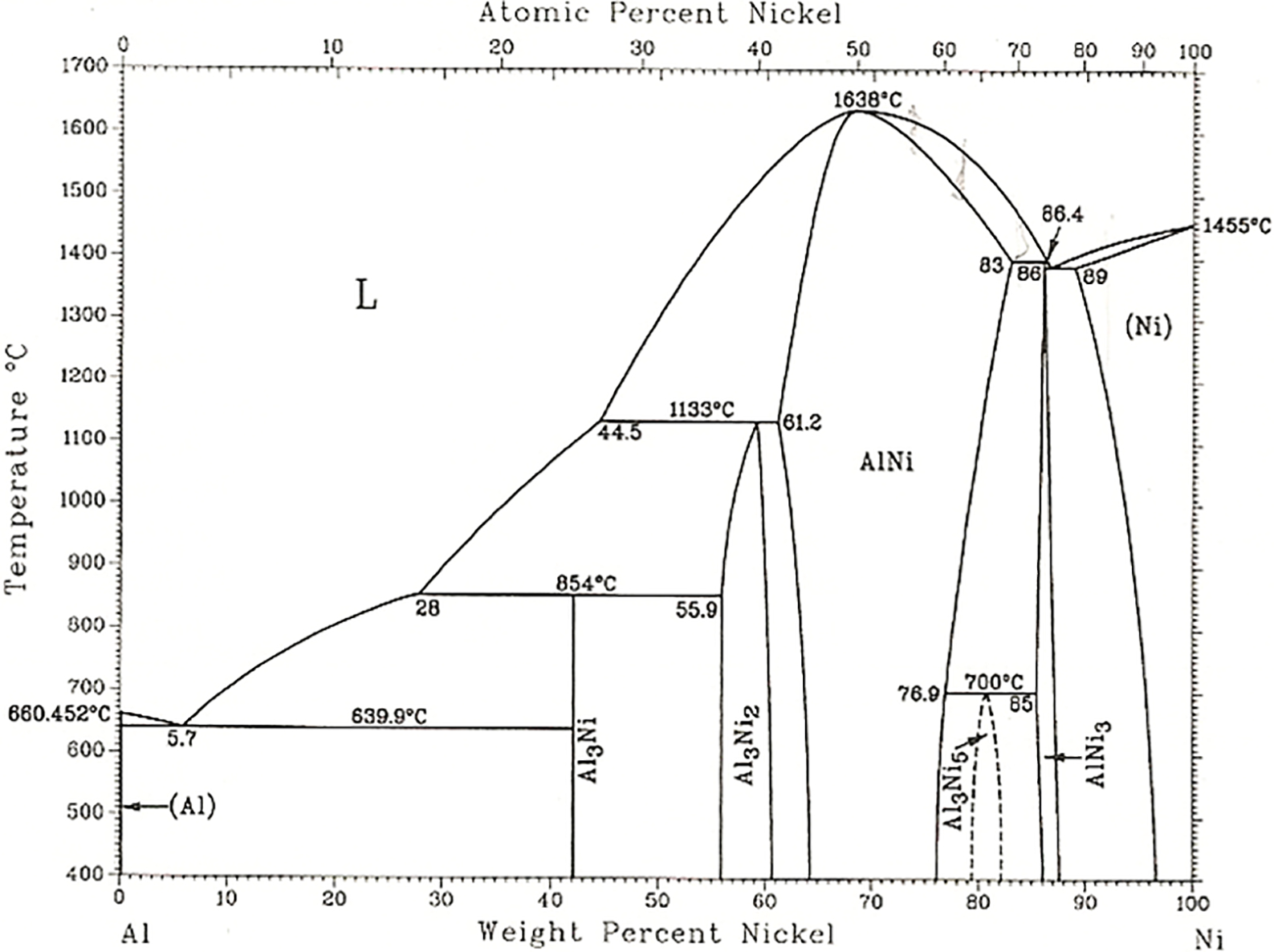
Binary Ni–Al system 15
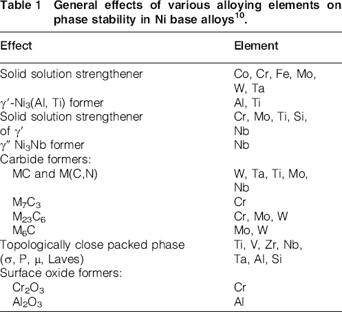
Ni base superalloys contain 10 or more elements. A wide variety of Ni base superalloys developed in the past 40 years have enhanced creep rupture properties and enhanced resistance to corrosion and oxidation. They can be solid solution strengthened or precipitation hardened alloys. The precipitation strengthened alloys contain γ′ precipitates of the type Ni3(Al, Ti) in a γ phase solid solution matrix. Table 1 shows the effect of various alloying elements.
10
Each element is added with a goal of obtaining a given property. The γ′ precipitates form when a supersaturated γ is cooled below the solvus temperature.
17
The precipitation kinetics and size distribution are sensitive to cooling rates and can also be sensitive to local variations in composition associated with microsegregation.10, 17 The following elements are added for strength and corrosion resistance: Al, B, C, Cr, Co, Hf, Mo, Nb, Re, Ru, Fe, Ti, W and Zr. In alloys that contain high concentrations of Nb, precipitation strengthening can occur by the precipitation of Ni3Nb (γ″). The formation of solid solutions is governed approximately by following the Hume–Rothery rules:18, 19
size factor: the component atoms must be of similar size with no more than 15% of difference in atomic radius crystal structure: component elements should have the same crystal structure valence: the atoms must have the same valency electronegativity: the atoms must have approximately same electronegativity. If the electronegativity difference is too great the metals will tend to form intermetallic compounds. General effects of various alloying elements on phase stability in Ni base alloys10.
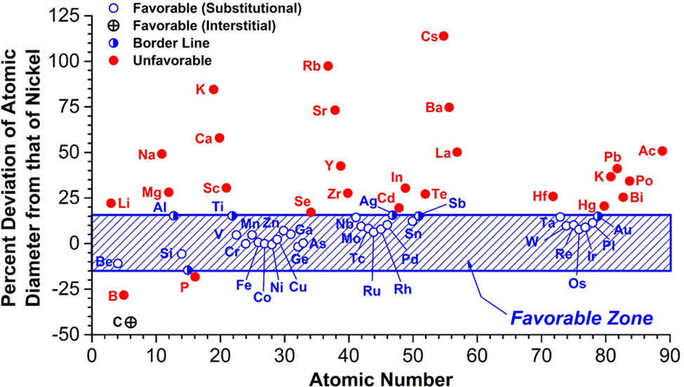
Deviations of atomic radius from that of nickel 20
The group V, VI and VII elements Co, Cr, Mo, W and Fe are the γ forming elements. The differences between their atomic diameter and that of Ni range from 3 to 13%. The group III, IV and V elements, such as Al, Nb, Ta and Ti, are the γ′ forming elements. The differences between their atomic diameter and that of Ni range from 6 to 18%. The carbide forming elements are Cr, Mo, W, Nb, Ti and Ta; the elements B, C and Zr segregate to the grain boundaries. The differences between their atomic diameter and that of Ni range from 21 to 27%.
Excess concentrations of any of the solid solution forming elements promote the formation of topologically close packed (TCP) phases. Al, Cr and Co improve the resistance of an alloy to corrosion, oxidation and sulphidation by aiding in the formation of a dense, adherent oxide film. B, C, Hf, and Zr are added to control grain size and microstructure. B, C, Hf and Zr form carbides and borides at the grain boundaries and strengthen the alloys.
Phases in Ni base superalloys
Phase diagrams can be valuable tools to understand phase equilibria, phase stability and microstructures. However, binary and ternary phase diagrams are only useful for simple systems (limited to two or three elements). The Ni base superalloys contain 10 or more elements. Therefore, phase equilibria calculations would be extremely valuable in understanding phases, phase stability and microstructure evolution in Ni base superalloys. CALPHAD based computational tools such as Thermocalc, DICTRA and TC-PRISMA enable accurate analysis of complex alloy systems such as Ni base superalloys. 21 These tools can significantly reduce the time for overall alloy development. The methodology is powerful enough to predict complex isothermal and isopleth (vertical) sections of phase diagram, liquidus temperature, partitioning of solute elements, growth and dissolution of phases such as TCP, solidification paths, transformation during heat treatment and the nucleation and coarsening rates for precipitates. Figure 3 shows calculated isothermal section of Ni–Al–Cr systems at 1000°C. Figure 4 shows the fraction of solid transformed from the liquid as a function of temperature for IN718 for both equilibrium and Scheil conditions. 21 The final part of the Scheil plot represents the formation of the Laves phase, which is well known to form in this alloy. 21 Most of the Ni base alloys are precipitation hardened alloys containing γ′ precipitates in a solid solution strengthened γ phase matrix. Saunders et al. 22 also describe recent developments in the database for CALPHAD type thermodynamic calculations for Ni base superalloys. These calculations allow for stable and metastable phase equilibria to be calculated. 22
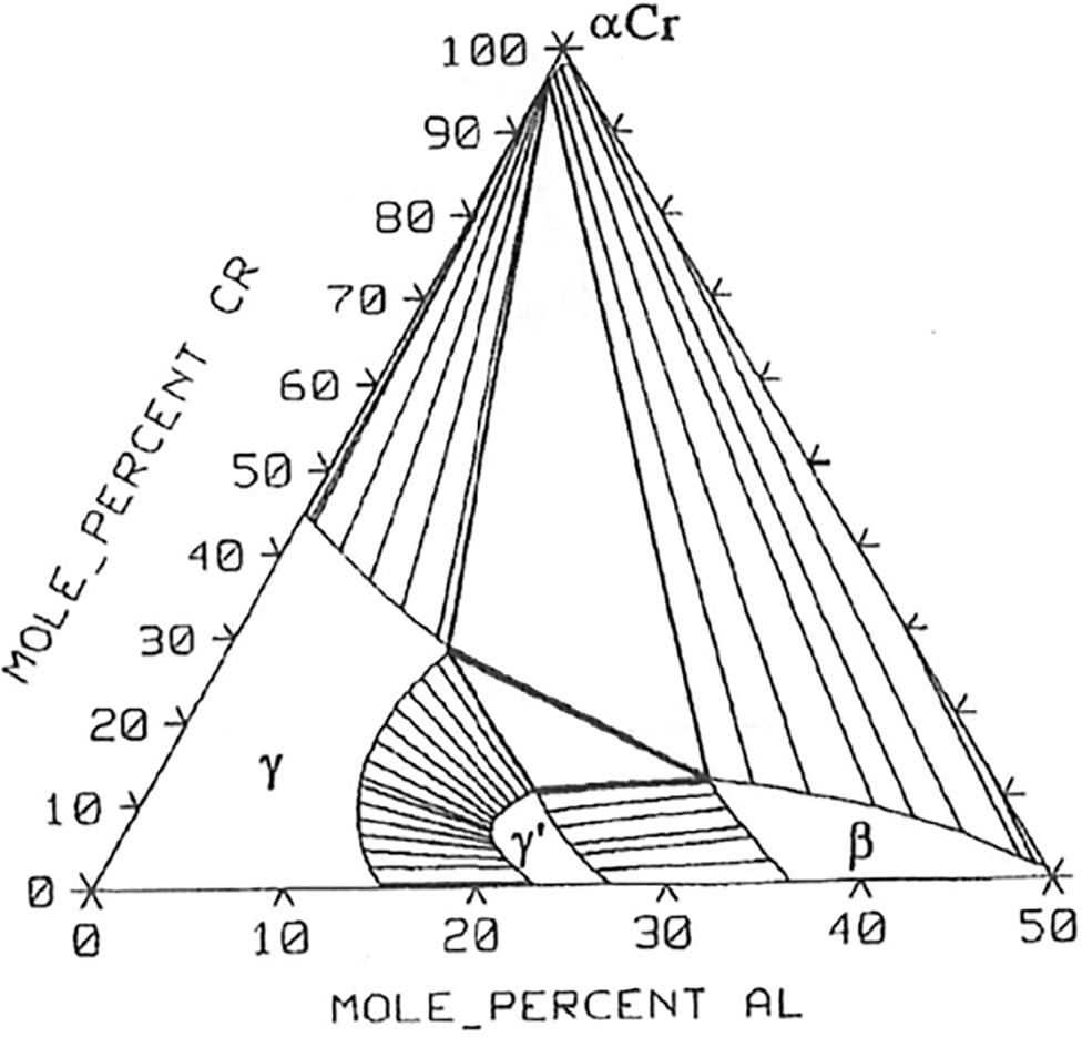
Calculated isothermal section of Ni–Al–Cr systems at 1000°C 21
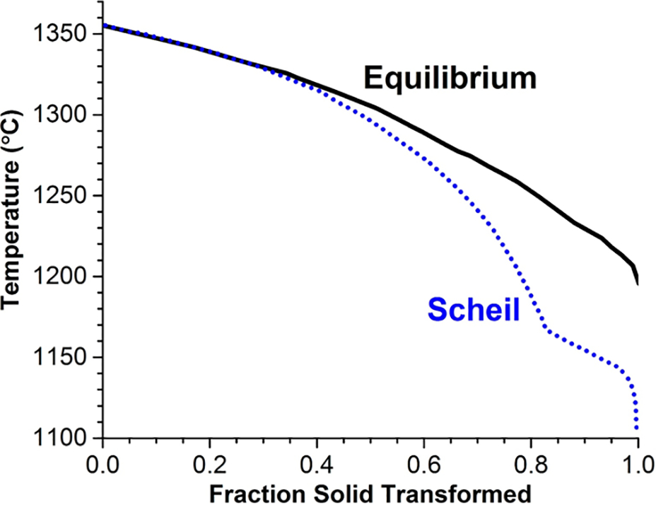
Fraction of solid transformed from liquid as function of temperature for IN718 for both equilibrium and Scheil conditions 21
γ phase
The γ phase with face centred cubic (fcc) crystal structure with Ni and Al atoms distributed randomly in the crystal lattice. It is Ni rich phase with other solutes including elements Co, Nb, W and Mo. Introduction of solute atoms of different sizes in the matrix creates strain in the lattice that stifles the motion of dislocations, thus increasing strength. Solid solution strengthened alloys are given a solution anneal treatment to ensure that all the alloying elements are in solution in γ phase and that no embrittling phases are left behind. The solution anneal is carried out at 1000 to 1200°C, and the time at temperature is controlled to limit grain growth. Rapid cooling is required after the solution anneal to avoid precipitation reaction. It should be noted, however, that some solid solution alloys can be used at compositions and temperatures in which the solubility limit is exceeded, and embrittling TPC phases can form at prolonged service times.
γ′ phase
The γ′ phase is an intermetallic compound of the type Ni3 (Al, Ti,) with an ordered L12 structure. The γ′ phase has a primitive cubic crystal lattice with Al atoms at the corners and Ni atoms on the face centres (Fig. 5). Figure 6 is a transmission electron microscopy micrograph showing cuboids of γ′ phase in a γ phase matrix in a Ni base superalloy. Sometimes, the γ′ phase observed in Ni base superalloys is not strictly stoichiometric; it may contain vacancies that lead to deviation from stoichiometry. The volume fraction of γ′ in aerospace Ni base superalloys is 0.7. 17 The effect of volume fraction of γ′ on creep is greater in single crystals than in polycrystalline Ni base superalloys. 23

L12 ordered crystal structure of γ′ phase
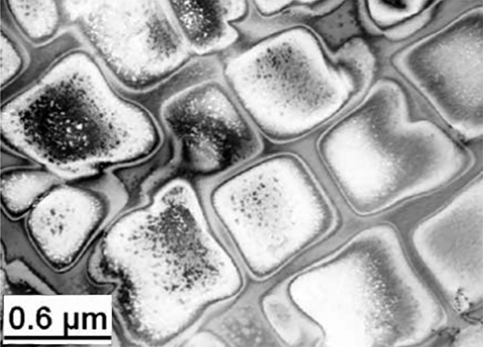
Transmission electron micrograph showing cuboids of γ′ phase in Ni base superalloy γ phase matrix 54
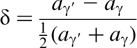
The interface between γ and γ′ can be coherent because γ and γ′ have similar crystal lattice parameters and form in cube–cube orientation relationships. However, the interface could have a small degree of lattice misfit between the two lattices, defined by
As discussed earlier, nickel base alloys derive their strength from the precipitation of γ′. Optimum strength is obtained by the presence of finely distributed particles. When a nickel base alloy is exposed to elevated temperature, the size, shape and the distribution of the precipitate change, leading to a loss of properties. During that period, small particles (particles less than a critical size) dissolve, and the particles larger than the critical size tend to grow. This phenomenon is known as ‘Ostwald ripening'or ‘coarsening’. In nickel base alloys, the kinetics of precipitate coarsening determine the performance of the alloy.
Coarsening of coherent precipitates has been the subject of many investigations,24–26 all aimed at understanding the various factors that determine alloy performance. In nickel base superalloys, the characteristics of the microstructure and the morphology of the precipitate depend on the lattice mismatch and the elastic properties (elastic anisotropy) of the precipitate and matrix.27–29 When the lattice mismatch is small, the interface between γ′ and the matrix is coherent, and when it is large, the interface is incoherent. The lattice mismatch is temperature dependent. In some alloys, elements have a tendency to partition between γ and γ′. Such partitioning can also change lattice mismatch or coherency. The lattice mismatch is an indicator of the amount of strain energy stored at the interface between γ and γ′. Precipitation of γ and γ′ generates elastic strain energy between phases, and the strain plays an important role in determining the sequence of events during transformation and microstructure evolution. When the difference in atom size between the matrix and the precipitate is small, the atoms across the interface fit themselves with significant distortion in the lattice. In the beginning, the energy associated with the distortion is small, and upon coarsening, the interfacial energy decreases, and the elastic interactions, which are strongly anisotropic, may control the coarsening rate and the morphology of the precipitate.30–33 Tsukada et al. have used phase field simulation to study the coarsening of precipitates in nickel base superalloys. In their research, elastic inhomogeneity was considered. If the material is elastically anisotropic, the precipitate is shaped in the form of plates or needles. Figure 7 shows precipitates as they coarsen and grow at high temperatures. 34 In nickel base superalloys, externally applied tension or compressive strains can also influence the shape and arrangement of the precipitates.
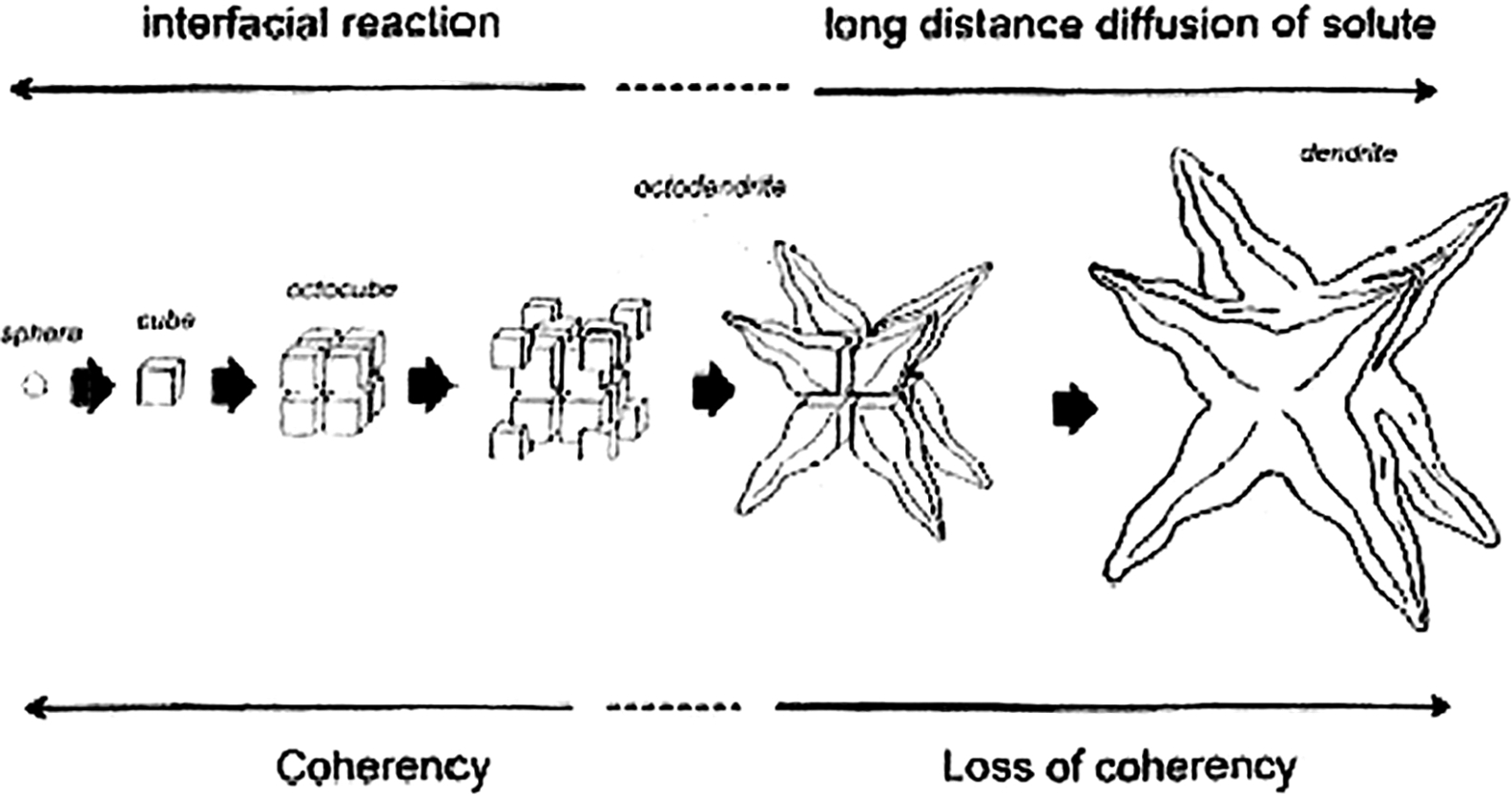
Shape change in γ′ precipitates as they grow and coarsen at high temperatures 30
Topologically close packed phase
Excess amounts of any of the solid solution forming elements (Mo, W, Nb, Cr and Co) promote the formation of undesirable TCP phases. The TCP phases are σ (tetragonal), μ (hexagonal) and P (orthorhombic) and are detrimental to nickel base alloys because they deplete the strengthening elements from the matrix and are embrittling. 17 They form when an alloy is exposed to very high temperatures and stresses. Deliberate alloy additions, such as 2% Ru as reported by Sato et al., 35 may be beneficial in retarding the formation of TCP phases.
Other notable phases
The G phase is a complex silicide of the nominal composition M6Ni16Si7, 36 which may form in Fe–Ni based alloys, 37 and has been observed in Ni base alloys after creep. 38 Its effect on properties is not well understood but is generally considered deleterious to properties as it depletes the grain boundary of Ti, Nb, Al, and other γ′ and carbide forming elements.
The Ni3Ti eta phase is an hcp phase similar in structure to the fcc γ′ phase. Eta generally forms in Ni base superalloys with high Ti/Al ratios during extended aging at high temperatures. 39 Its formation generally progresses through dissolution of existing g′ precipitates, thus reducing the total volume fraction of γ′. Thus, while it is not an embrittling phase, it is generally considered deleterious to strength,40, 41 although qualitative and quantitative studies show in some cases it has no effect on mechanical properties42–44 or can be used to improve properties such as crack growth resistance. 45
Carbides
Carbides strengthen a matrix by reducing the stacking fault energy.
23
Carbon and B, along with Hf, Zr and Ti, are added to control grain size and microstructure. Carbon in the level of 0.05 to 0.28 wt-% in Ni base superalloys forms carbides with Ti, Hf, Zr and other refractory elements. These carbides mostly form along the grain boundaries and prevent them from sliding and thus strengthen the alloys. The primary carbide, MC, forms directly from the liquid during solidification and subsequently transforms to M23C6, M6C and M2C3 carbides during heat treatment or service by the reactions
46


Strengthening mechanism
Many microstructural sources control the strengthening of Ni base superalloys. They include precipitation, Hall–Petch effects and interaction between precipitates and dislocations. A major source of strength of Ni base superalloys is precipitation hardening. This is mainly from the interaction of dislocations with precipitates. Precipitate strengthening is the most effective way of obtaining alloys with desired combination of strength and ductility. The precipitates stifle the motion of dislocations. Moreover, the precipitates in Ni base alloys Ni3 (Al, Ti,) have an ordered structure. Dislocations find it hard to penetrate precipitates with an ordered structure.
Any theory that explains hardening due to the interaction between dislocations and precipitates should consider the influence of a number of factors, such as changes in stacking fault energy, effects of coherency strains, precipitate crystal structure and mismatch in elastic modulus between precipitates and the matrix. 47 Precipitation strengthened Ni base superalloys have relatively high tensile properties at room temperature. The yield strength ranges from 900 to 1000 MPa, and the ultimate tensile strength ranges from 1200 to 1600 MPa. 17 In addition, the Ni base superalloys exhibit an unusual yield strength phenomenon as a function of temperature. 17 Unlike the yield strength of conventional alloys, which decreases as the temperature increases, the yield strength of Ni base superalloys increases with an increase in temperature (Fig. 8). This phenomenon, known as ‘the yield strength anomaly’, is mainly due to the unusual flow behavior of the γ′ phase. 17
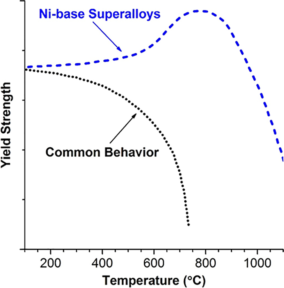
Yield strength anomaly: yield strength of Ni base superalloys increases with temperature, mainly as result of unusual flow behavior of γ′ phase
A proposed dislocation–precipitate interaction model that explains the yield strength anomaly has been generally accepted. 48 When a dislocation approaches a γ′ precipitate, they dissociate in the γ′ phase, leading to the formation of antiphase boundaries (APBs). At elevated temperatures, one set of partial dislocation bounding APBs cross-slips into a low energy plane, creating a microstructural ‘Kear–Wilsdorf Lock’, 48 and the cross-slipped dislocation cannot move without dragging the APB. It requires higher stresses to move the locked dislocation; thus, the yield strength is increased.
The strengthening mechanism contributing to the improved strength of the Ni base superalloys is more complex, and many strengthening mechanisms could be in operation. Many analytical models have been developed to explain strengthening in Ni base superalloys.49, 50 These models consider one or two mechanisms. A comprehensive model that considers contributions of specific feature of the microstructures to the overall strength of the material is required. Recently, Kozar et al. 51 have developed one such model. It takes into consideration contributions from solid solution strengthening, Hall–Petch effects, precipitate shearing and interactions between precipitates and dislocations.
Further advances are being made in understanding the strengthening mechanisms in Ni base superalloys. The dislocation–dynamics computer simulations developed recently should aid in the study of metal deformation from a fundamental point of view. 47
Heat treatment and precipitate morphology
Heat treatment of Ni base superalloys is recommended for obtaining a high volume fraction of γ′ and a distribution to obtain optimum properties. Several types of heat treatments are given to wrought, cast and welded parts for annealing, homogenisation and stress relieving. 10 Precipitation of strengthening phases is carried out after solution treatment. The solution treatment is carried out at a high temperature to take the precipitates and other elements and phases into solution and forms a supersaturated solid solution. This part of the heat treatment also serves to relax concentration gradients that form due to microsegregation from solidification of the initial ingot. This heat treatment is conducted at a temperature above the γ solvus temperature. Grain growth can also occur at the solution treating temperatures. The temperature and time should be monitored to avoid excessive grain growth. The aging treatment is carried out at subsolvus temperatures and should be monitored for controlling the size and distribution of carbides and the γ′ and γ″ strengthening phases. 24
Solid solution strengthened alloys are generally supplied in a solution annealed condition. 10 Most of the alloys are solution annealed in the temperature range of 1000 to 1200°C. Sometimes rapid cooling from solution temperature is carried out to prevent formation of carbides. During welding, the weld metal of the solid solution strengthened alloys solidifies as austenite; solute segregation and second phase formation take place in the last liquid to solidify. Several changes, such as recrystallisation, grain growth and particle dissolution, can occur in the microstructure of the heat affected zone (HAZ). Grain boundary liquation can occur in some cases. In welding of solid solution strengthened alloys, post-weld heat treatment (PWHT) is used for relieving residual stresses, homogenisation and phase dissolution. Reduction in residual stresses occurs by stress relaxation. 52 The phases that form in the fusion zone and in the HAZ are taken into solution by diffusion. The solution kinetics have been well established for the non-equilibrium phases that form during solidification. 53
In the case of precipitation hardened alloys, weld metal properties are typically inferior due to segregation of solute elements during solidification of weld metal. The properties can be improved by a PWHT followed by an aging treatment.
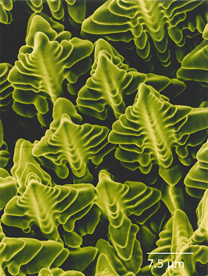
The general solidification pattern of the weld metal produces a microstructure containing primary γ phase with a γ+γ′ interdendrite eutectic. For a number of alloys, formation of γ′ in the primary γ cells is not possible due to slower kinetics of γ′ nucleation and growth at the rapid cooling rates of the weld. However, γ′ was observed in some cases within the primary γ cells and in the interdendritic eutectic (Fig. 9). 54 The nucleation rate is high in Ni base superalloys mainly because of the low lattice mismatch between γ and γ′, the associated strain energy and the low activation energy. The cooling rate has a significant influence on the γ′ number density, morphology and size. Using Gleeble thermomechanical simulator, Babu et al. 54 have shown that the size, number density and morphology of the γ′ phase in a CM 247 DS alloy change drastically when the cooling rate is varied. 54 There is a significant increase in number density, change in size and morphology of γ′ as a function of cooling rate (Fig. 10).
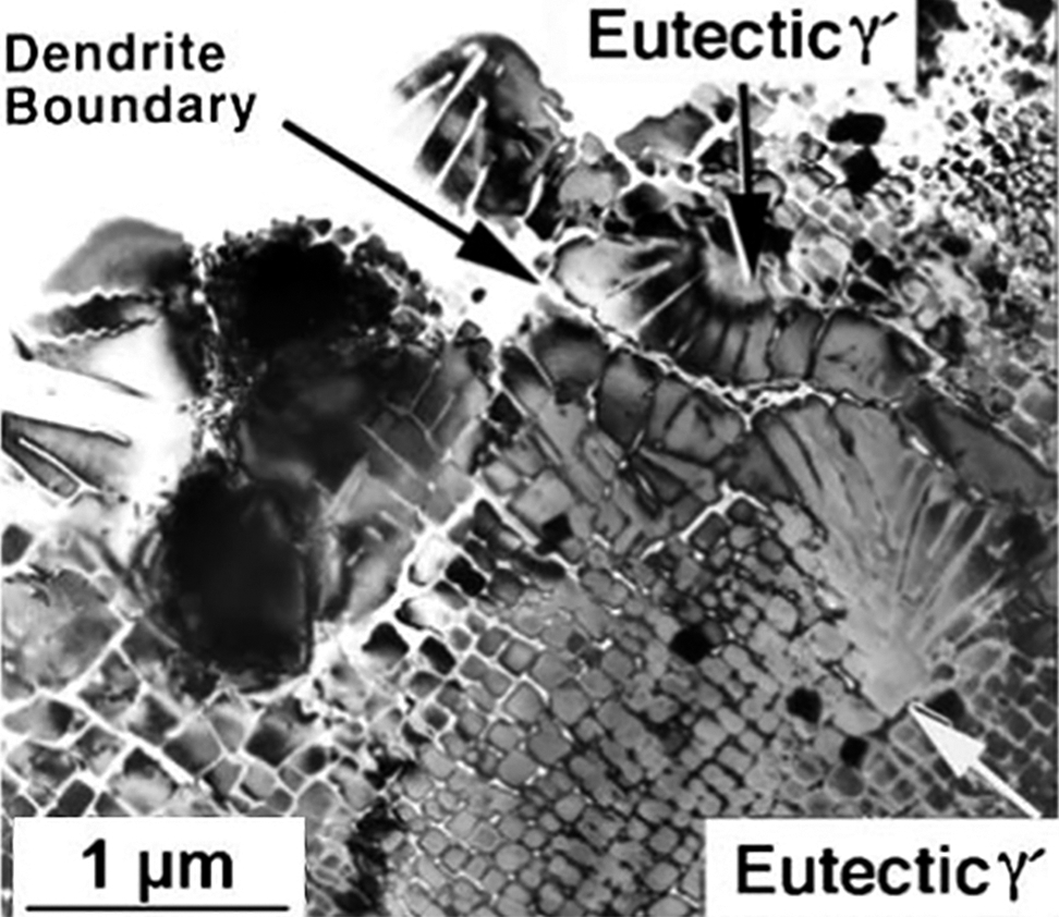
γ′ phase within primary γ cells and in interdendritic eutectic 54
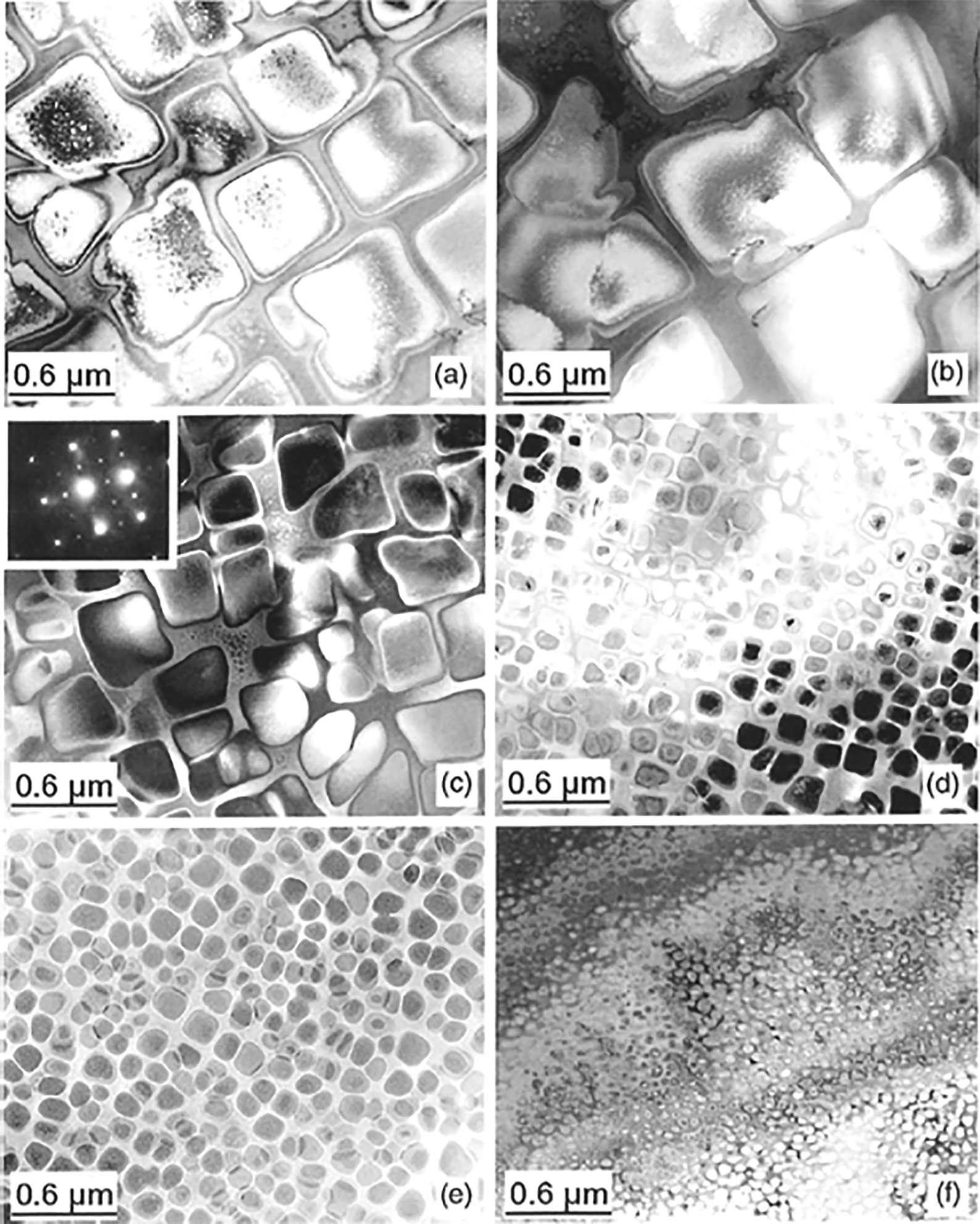
Increases in number density, change in size and morphology of γ′ as function of cooling rate 54
Properties of Ni base superalloys are influenced by the morphology of the precipitates.55, 56 In addition to morphology, the size, volume fraction and population of precipitates are critical to properties. Gabb et al. 57 have developed and validated a physics based model that incorporates supersaturation, nucleation and growth and coarsening to predict γ′ structure.
Nickel base alloys—fundamentals of solidification
The characteristics of weld metal (the fusion zone) depend to a large extent on the solidification behavior of the weld metal. Solidification behavior controls the extent of elemental segregation, the size and shape of grains and defects such as hot cracking. It is well known that there are similarities between solidification behavior of weld metal and cast metal. In fact, a weld metal can be considered to be a miniature casting, and hence, most of the theories developed for casting or ingots and single crystal solidification can be extended to the weld metal solidification behavior.58–60 David and Vitek defined various parameters that control weld pool solidification and the development of weld metal microstructure, in particular, the conditions necessary for the formation of plane front, cellular, cellular dendritic and dendritic solid morphologies.
During alloy solidification, extensive solute redistribution occurs, leading to segregation of elements.
61
Segregation on a fine scale of the order of dendrite arm spacing (the perpendicular distance between two primary, secondary or higher order branches) is known as ‘microsegregation’; large scale segregation (the spacing of several dendrites) is called ‘macrosegregation’. The primary interest during the solidification of nickel base alloy weld metal is solute redistribution because it influences the properties and hot cracking tendencies of the alloy. Because of the similarities between castings and weld metal solidification, models of solute redistribution developed for castings can be extended to solute redistribution in nickel base alloy welds. The Schiel equation,
62
which is ‘the classical non-equilibrium solidification equation’ for solidification of nickel base alloys for constant partition ratio, can be written as
The derivation of equation (1)
c
is based on the following assumptions:
equilibrium is maintained at the solid and liquid interface mixing in the liquid is complete undercooling at the dendrite tip is negligible there is no diffusion within the solid.
Some diffusion of solute elements always takes place during solidification even though the non-equilibrium equation for solidification assumes no diffusion. Brody and Flemings
45
developed a model to account for this diffusion in the solid. The modified Schiel equation allowing for solid state diffusion is
For α<1, microsegregation approaches the maximum predicted by the classical Schiel equation. For α>1, the composition of the primary solid approaches uniformity. One of the assumptions in deriving the above equations is that there is no dendrite tip undercooling due to the curvature effects. This indeed may not be true, particularly for welds made at high welding speeds and for finer dendritic structures. The total undercooling at the dendrite tip can be written as
For most of the solidification cases, the kinetic undercooling ΔTk is negligible and can be neglected.
58
The Scheil equation describes solute redistribution when diffusion in the solid is insignificant. Many studies have used these simple concepts to explore the solidification behavior in Ni base alloy weld metals.64–71 These studies have demonstrated that the solute redistribution behavior and resultant weld metal microstructure are controlled primarily by the pertinent values of k and Ds for the alloying elements of interest. The value of Ds will control the potential for back diffusion in the solid during solidification. The value of k describes how strongly an alloying element partitions to the liquid and solid phases during solidification. Elements that exhibit values of k < 1 segregate to the liquid during solidification. Elements with very low k values can produce steep concentration gradients across the cellular or dendritic substructure of the weld. However, the elemental gradient can be eliminated if solid state diffusion of that particular element in the solid is high enough.
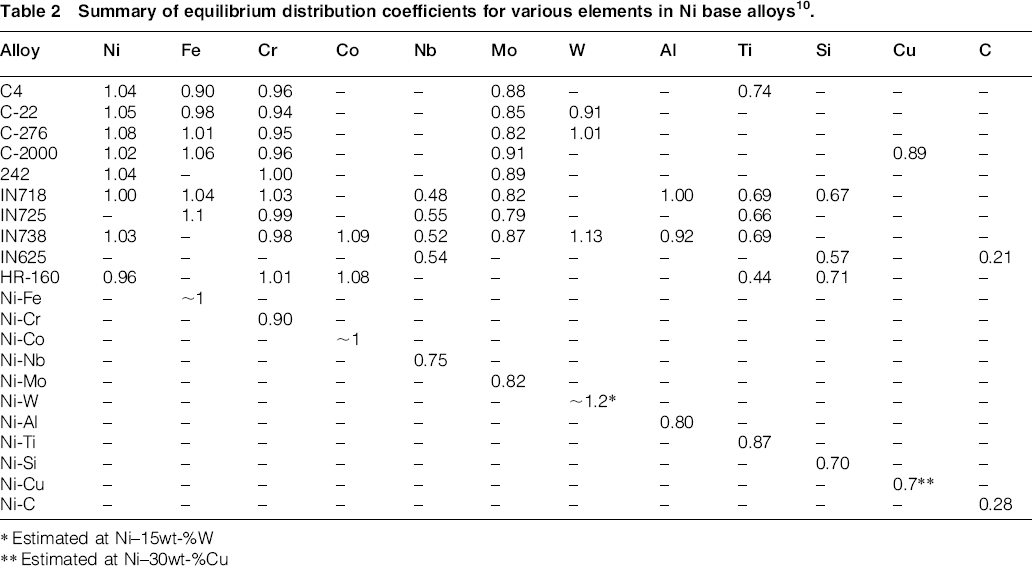
Upper bound values of α for important alloying elements in Ni have recently been reviewed. 10 The values of tf and L depend on cooling rate and can also be estimated. Figure 11 shows α values as a function of cooling rate for many substitutional alloying elements in Ni. The α value decreases with increasing cooling rate due to the decrease in solidification time tf with increasing cooling rate. More importantly, note that α<1 for all the elements considered under all cooling rate conditions. An upper bound value of Ds was calculated at a typical liquidus temperature of 1350°C (2460°F). The value of α can only decrease with the use of Ds values calculated at lower solidification temperatures.
Plot of parameter for wide range of substitutional alloying elements in Ni base alloys 10
These results clearly demonstrate that solid state diffusion of substitutional alloying elements in nickel alloys is insignificant during solidification of fusion welds. Experimental evidence has been published that supports these calculations for a variety of elements, including Fe, Cr, Nb, Mo and Si.71, 72 Calculation of the α parameter for C in Ni will yield values that are significantly greater than unity. This is to be expected, since C diffuses by an interstitial mechanism and therefore exhibits diffusion rates that are orders of magnitude higher than the substitutional alloying elements. More detailed back diffusion model calculations of C in welds of nickel alloys have been conducted and demonstrate that solid state diffusion of C (and N) can be expected to exhibit complete diffusion in the solid during solidification. 71
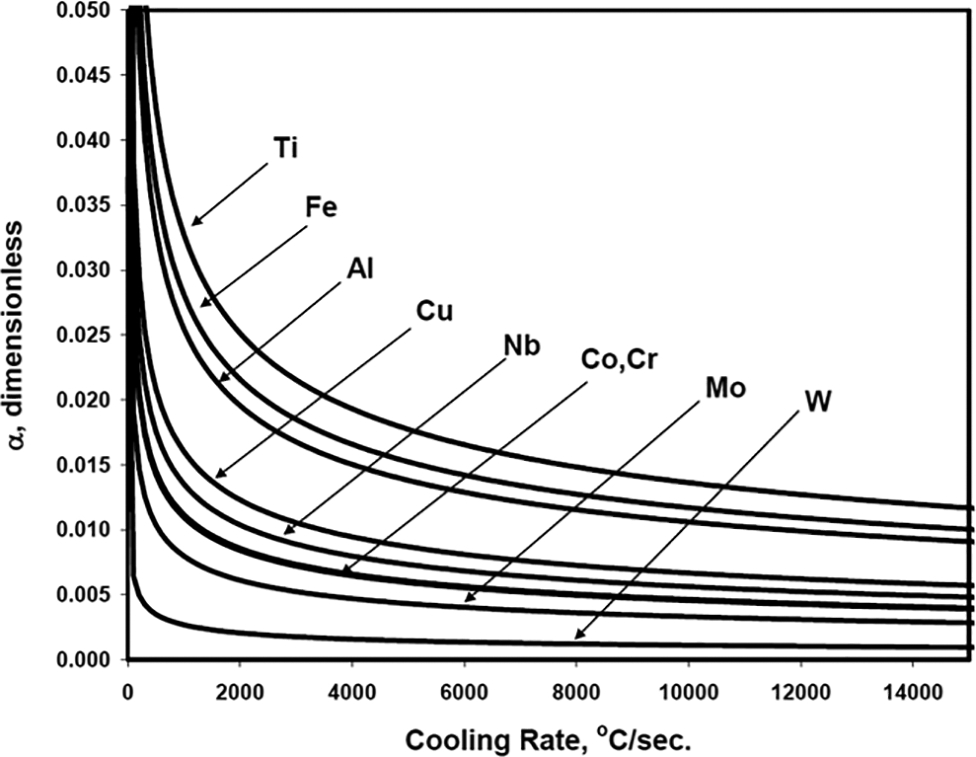
The lack of appreciable solid state diffusion of substitutional alloying elements during solidification of fusion welds in Ni alloys has important implications. First, it indicates that solute redistribution and the final concentration gradients across the cellular/dendritic substructure in fusion welds of Ni base alloys produced under cooling rate conditions typical of arc welding can be calculated with reasonable accuracy using the simple Scheil equation. (Welds produced with high energy density processes may experience dendrite tip undercooling that would reduce the extent of microsegregation.) Second, it demonstrates that, except for the case where k = 1, some level of microsegregation can always be expected in the as solidified weld. Examples of this are shown in Fig. 12 for fusion welds in alloy 740H that was recently developed for use in AUSC power plants. 73
a light optical micrograph of region of interest; b concentration profile for major alloying elements; c concentration profile for γ′ forming elements 80 Composition line scan across dendrites in single pass as welded IN740H
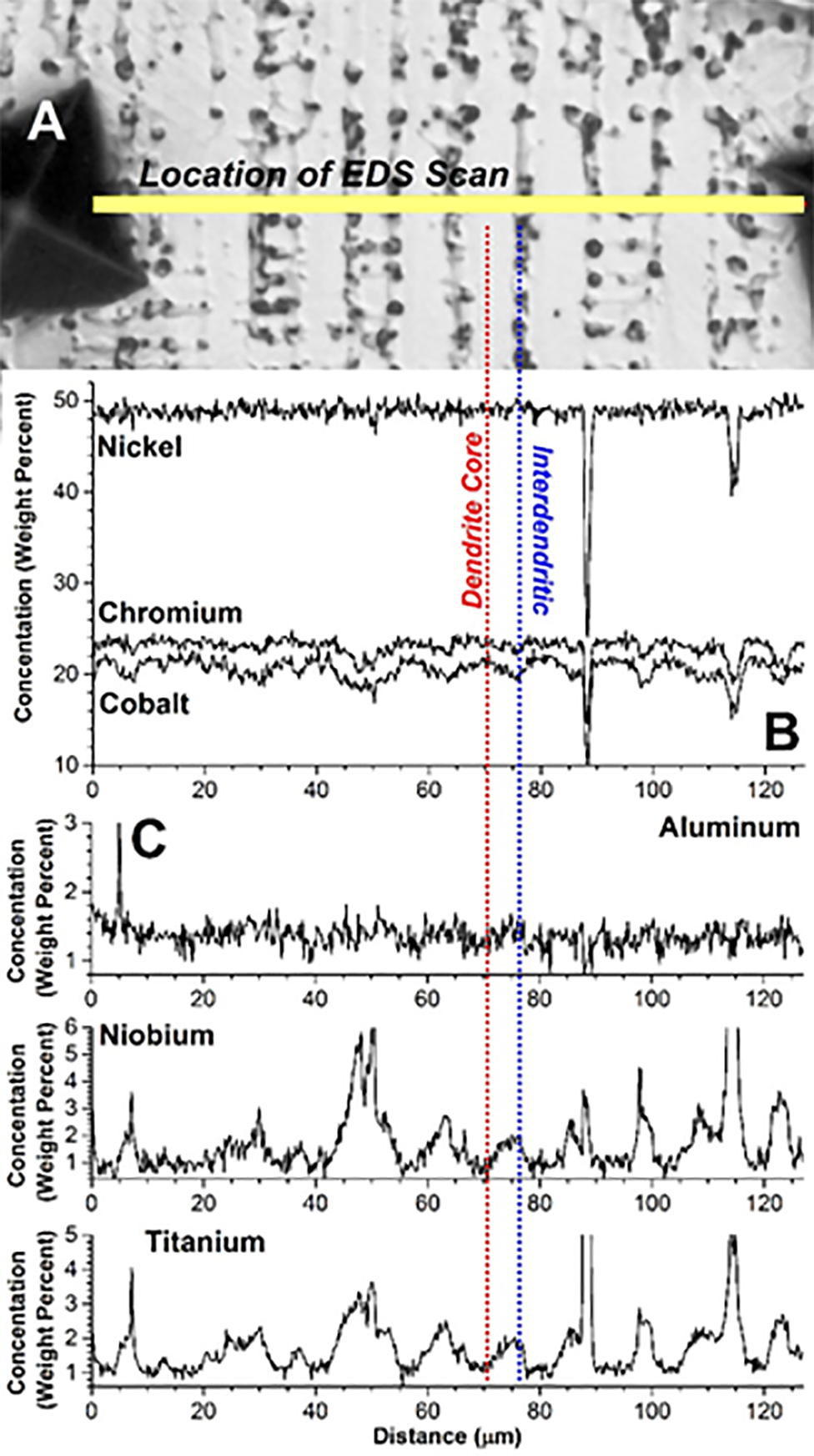
The final degree of microsegregation can be assessed by direct determination of the k value for the element of interest, where the degree of microsegregation will increase with decreasing k value (for k values < 1). For example, the lowest concentration will occur at the dendrite core where solidification initiates, and the concentration at this location is given by kC0. Table 2 summarises experimentally measured k values determined in welds for a range of alloying elements in Ni base alloys that find use in energy applications. 10 The table includes both solid solution and precipitation strengthened alloys, since the segregation behavior of an element during solidification is independent of its intended purpose. Values for pertinent binary Ni alloys are also provided for reference. It should be noted that nearly all these values represent electron probe microanalysis measurements in which the core composition is measured, and k is then determined by the ratio of the core to nominal composition, k = Ccore/C0. Thus, these values represent k at the start of solidification and do not account for variations in k that may occur during solidification as the temperature decreases.
Summary of equilibrium distribution coefficients for various elements in Ni base alloys 10 .
Estimated at Ni–15wt-%W
Estimated at Ni–30wt-%Cu
Note that, except for Nb and perhaps Si and Ti, there are not large differences between the segregation behavior exhibited by complex multicomponent alloys and the Ni–X binary systems. The segregation potential of Nb is important for controlling microstructural evolution in superalloys that rely on the γ″-Ni3Nb phase for strengthening. The value for Nb is lower in the multicomponent alloys than the simple binary Ni–Nb system. This indicates that the presence of other alloying elements decreases the solubility of Nb in Ni. The data also show that elements with similar atomic radii to Ni, namely Fe, Cr and Co, have k values that are close to unity. This trend is expected based on the influence of atomic size difference on solubility, where elements of similar atomic radii generally exhibit appreciable solubility. The atomic radii differences of Fe, Cr, Co compared to Ni are less than 1% for all these elements. Thus, although these elements cannot back diffuse during solidification, their concentration gradients are not large to begin with because their k values are all close to unity. This behavior is particularly beneficial for Cr, which is used for corrosion protection by formation of a passive Cr2O3 scale. The presence of significant concentration gradients would lead to preferential attack in the dendrite cores for alloys that rely exclusively on Cr as a passive film former. In fact, preferential corrosion often occurs at the dendrite cores in welds of Mo bearing alloys due to microsegregation of Mo. 74 Reference to Table 2 indicates that this can be directly attributed to the somewhat low value of k for Mo. The behavior of tungsten (W) is surprising and not well understood. Tungsten is appreciably larger than Ni (10% larger atomic radius) and exhibits a different crystal structure (body centred cubic), yet shows very little tendency for segregation in Ni alloys. This makes W attractive for solid solution strengthening. Carbon exhibits the greatest partitioning behavior of the elements listed in the table, and this accounts for the formation of various carbide phases (most notably the MC type) at the end of solidification in many Ni base alloys. Although there is strong partitioning to the liquid phase during solidification, the final carbon distribution in the solid can be expected to be uniform due to the high solid state diffusivity of C in fcc Ni.
Secondary phase formation during solidification
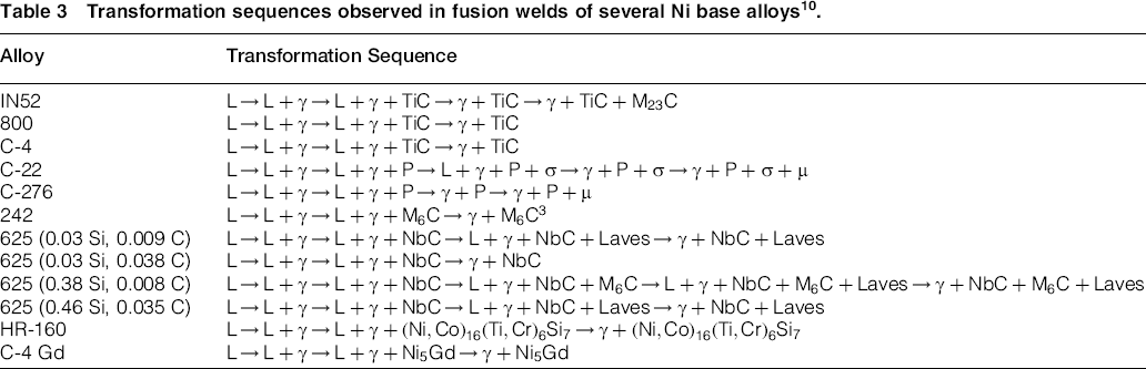
The redistribution of alloying elements between the liquid and solid that occurs as the weld solidifies can lead to significant solute enrichment in the liquid at the terminal stages of solidification that, in turn, can produce secondary phases. Typical phases that can form in a variety of solid solution and precipitation strengthened alloys are discussed in this section. The phase transformation sequences observed in fusion welds several Ni alloys are summarised in Table 3. 10 The table is not meant to represent an all inclusive list of microstructure evolution in commercially available alloys, but provides examples from the available classes of alloys that can be used to identify general trends between alloy composition and fusion zone microstructure.
Transformation sequences observed in fusion welds of several Ni base alloys 10 .
Fusion welds in relatively simple Ni–Fe–Cr type alloys with only minor alloy additions generally solidify predominately in the fully austenitic mode. This is expected based on the Fe–Ni–Cr liquidus projection, which indicates that austenite is the only stable phase associated with solidification temperatures at the Ni rich end of the Fe–Ni–Cr system. Additions of carbon to these alloys often lead to precipitation of M23C6 type carbides in the solid state during the cooling portion of the weld thermal cycle, which is attributed to the decreasing solubility of C with decreasing temperature. The simultaneous presence of C and strong carbide forming elements such as Ti and Nb can lead to the formation of MC type carbides in the interdendritic regions at the terminal stages of solidification by eutectic type reactions involving γ and MC phases. This has been observed in a number of Ni–Fe–Cr type alloys, such as alloy 800 and filler metals 52 and 82.75, 76
Microstructure evolution in fusion welds of Ni–Cr–Mo type alloys is more complicated due to the potential formation of intermetallic TCP phases such as σ, μ and P that are stabilized by the presence of Mo. Tungsten additions also stabilize these TCP phases. These phases are generally undesirable from both a weldability and properties point of view. Their formation has been shown to extend the solidification temperature range and increase solidification cracking susceptibility. Their complex crystal structure leads to limited slip systems, which makes these phases brittle and can lead to reduced toughness and ductility if they are present in high proportions. Their high Cr and Mo contents will reduce the Cr and Mo concentrations in the austenite matrix, thereby reducing corrosion resistance.
Using alloys C-22 and C-276 as an example, the formation of these phases during weld solidification can be understood with calculated multicomponent liquidus projections and solidification models as shown in Fig. 13. 76 These multicomponent liquidus projections account for phase stability at the solidification temperatures. The influence of all alloying elements on position of the phase boundary lines is also taken into account. The arrows in the diagrams represent the solidification path as calculated using the ternary analog of the Scheil equation. Here, the start of the arrow represents the nominal alloy composition, and the arrow represents the variation Cr and Mo concentration in the interdendritic liquid as solidification proceeds. These results show that the P phase is a product of solidification for both alloys. For C-22, both P and σ form during solidification, while only the P phase forms during solidification of alloy C-276. This difference is caused by variations in Cr contents between the two alloys and its associated effect on the solidification path. Alloy C-22 is higher in Cr than C-276 (21 versus 16 wt-%). As a result, the end of the primary L → γ solidification path for C-22 is located very close to the three phase γ-P-σ ternary eutectic point. Thus, the liquid composition only has to ‘travel’ a small distance after initial formation of P phase before the σ phase will form. The lower Cr content of alloy C-276 causes the end of the primary L → γ solidification path to intersect the γ/P phase boundary farther away from the three-phase γ-P-σ ternary eutectic point. Thus, the remaining interdendritic liquid is consumed along this line by the L → γ + P reaction before the ternary type eutectic point is reached, avoiding formation of the σ phase. For each alloy, μ forms in the solid state by decomposition of the P phase.
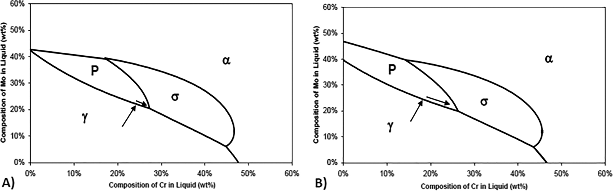
Liquidus projections calculated with Thermocalc and solidification paths calculated with ternary version of Scheil equation for a alloy C-22 and b alloy C-276 77
Several Ni alloys slated for advanced energy applications depend on either the γ′- Ni3(Ti,Al) or γ″-Ni3Nb precipitate for elevated temperature strength. Microstructural evolution in the fusion zone of γ′ forming alloys can be understood with the aid of the diagrams shown in Fig. 14, which represent schematic illustrations of the Ni–Al–Ti liquidus projection and a vertical section through the Ni–Al–Ti system. 10 For alloys with low C contents (typically less than ∼0.01 wt-%), the γ and γ′-Ni3Al phases are the main constituents that form in these alloys. The Ni3Ti phase can also form during solidification, but this phase is less desirable from a mechanical property standpoint. For an alloy of composition C0, solidification begins with primary γ solidification. As solidification proceeds, Al and Ti segregate to the liquid since their k values are less than 1. Thus, the liquid composition moves away from the Ni rich corner and traces out a solidification path (dotted line in Fig. 14) that is directed towards the γ/γ′ monovariant eutectic line. Since γ′ (and not Ni3Ti) is the preferred phase, and Ti segregates to the liquid more aggressively than Al (Ti has a lower k value than Al), more Al than Ti is generally required to promote intersection of the primary solidification path with the γ/γ′ eutectic line instead of the γ/Ni3Ti eutectic line. Many alloys do indeed have more Al than Ti, and this is reflected in the position of the nominal composition C0 shown in Fig. 14. The primary solidification path intersects the γ/γ′ monovariant eutectic line at Ce (the eutectic composition), and the liquid composition then moves down this eutectic line as γ and γ′ form simultaneously from the liquid by a eutectic type reaction. Since this system is not a simple binary, the eutectic composition at the intersection point Ce depends on the nominal composition and pertinent k values of Al and Ti, and the eutectic type reaction occurs over a range of composition and temperature. Strictly speaking, the Ni3Ti phase would also be expected to form near the end of solidification as the liquid composition would eventually intersect the three phase γ-Ni3Al–Ni3Ti equilibrium point, but this is generally not observed in practice. The general solidification sequence accounts for the formation of γ dendrites and the interdendritic γ/γ′ eutectic that has been observed in many commercial Ni base superalloys.77–79
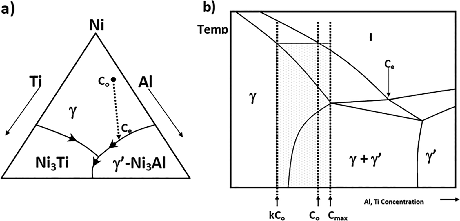
a schematic illustration of Ni–Al–Ti liquidus surface and b schematic illustration of vertical section through Ni–Al–Ti system 10
Microstructural evolution is generally not complete after solidification of γ′ forming alloys. The primary γ phase will exhibit a range of Al and Ti concentrations due to microsegregation that is associated with the low diffusivity of Al and Ti in the primary γ. The primary γ phase will contain compositions ranging from kC0 at the cell core to Cmax at the cell boundaries, where Cmax is the maximum solid solubility of Al and Ti in γ. (The γ substructure is referred to here as cellular for simplicity, but can also be dendritic depending on alloy content, welding parameters and resultant temperature gradient in the liquid. It should also be noted that phase compositions can generally not be determined directly from a vertical section as shown in Fig. 14 since the tie lines may not lie in the plane of the diagram. The compositions are shown here for reference only.) The composition range is represented by the shaded region in Fig. 14. Note that, depending on location within the γ cellular substructure, the cells may enter into the two phase γ+γ′ region upon further cooling, and precipitation of the γ′ phase becomes thermodynamically possible.
For many engineering alloys strengthened by precipitation, the kinetics of nucleation and growth are too slow to permit precipitation during the relatively high cooling rates associated with most weld thermal cycles. However, precipitation of the γ′ phase within the γ cells is routinely observed in the fusion zones of these alloys. This can be attributed to the excellent crystallographic matching across the γ/γ′ interface that leads to very low surface energy and strain energy. The nucleation rate increases exponentially with decreasing activation energy required for nucleation. The activation energy, in turn, decreases with decreasing surface and strain energy. Thus, the good crystallographic matching leads to high nucleation rates that permit formation of γ′ even under high cooling rate conditions typical of welding. The final weld microstructure will therefore consist of cored γ dendrites that contain γ′ precipitates with γ/γ′ eutectic at the solidification subgrain (cell and dendrite) boundaries. Figure 15 shows an example of the gradient in γ′ content that occurs in alloy 740H as a result of the microsegregation. 80
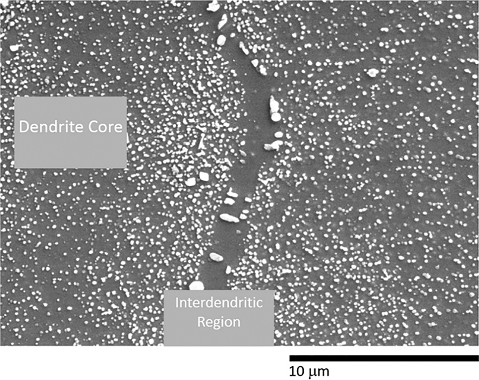
Variation in γ′ content across dendritic substructure of fusion weld in alloy 740H; γ′ content is low in dendrite core due to low Al and Ti concentration at that location 80
As previously mentioned, many superalloys have been developed that contain significant amounts of Nb as a strengthening element that is added to form the γ″ phase. The reaction sequence observed in Nb bearing superalloys is similar to that expected in the ternary Ni–Nb–C system. The liquidus projection for the Ni–Nb–C system was estimated by Stadelmaier and Fiedler, 81 and the Ni rich corner of this diagram is redrawn in Fig. 16. 10 The liquidus projection exhibits three primary phase fields of interest: γ, NbC and Ni3Nb. A primary C (graphite) phase field exists at high C contents, but is not of interest. Additions of Fe, Cr and Si to the Ni–Nb system are well known to promote Laves at the expense of Ni3Nb. Thus, by replacing Ni3Nb with Laves, the Ni–Nb–C liquidus projection can be utilised as a guide in developing a qualitative description of the solidification reaction sequences in Nb bearing superalloys. Solidification begins with formation of primary γ dendrites which, upon forming, reject Nb and C to the liquid. As solidification proceeds, the liquid composition moves away from the Ni rich corner (dotted line in Fig. 16), becoming progressively richer in Nb and C until it reaches the monovariant eutectic line between γ and NbC. At this point, γ and NbC form simultaneously from the liquid by a eutectic type reaction as the liquid composition travels down the eutectic line. Owing to the high C content of NbC (∼9.5 wt-%), its formation depletes the liquid of C, while the Nb content of the liquid continues to increase. If the C content of the alloy is high enough and the Nb content low enough, then solidification can be completed along γ/NbC eutectic line and no Laves phase will form. 79 For most alloys however, this does not occur and the liquid composition continues to be enriched until the Laves phase forms. According to the simple ternary Ni–Nb–C liquidus projection, solidification should terminate with the ternary L → (γ + NbC+Laves) ternary eutectic reaction, where the liquidus surface is at an apparent minimum. Under this condition, the γ, NbC and Laves phases should be intermixed. However, this type of structure is not observed in alloys that form both the NbC and Laves phases. 79 Instead, the γ/NbC and γ/Laves eutectic type constituents are always distinctly separated. This indicates that the actual liquidus projection for multicomponent alloys is more properly represented by a class II reaction in which the local minimum on the liquidus surface occurs where the γ/Laves eutectic line intersects the ‘Ni–Nb binary’ side of the diagram. This accounts for the spatially separate γ/NbC and γ/Laves eutectic type constituents that are observed experimentally.
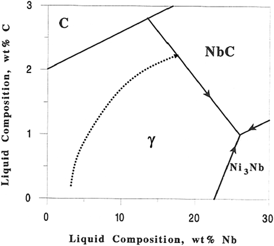
Schematic illustration of primary solidification path (dotted line) of Ni rich alloy superimposed Ni rich corner of Ni–Nb–C liquidus projection (solid lines) 10
Reaction temperatures and associated secondary phases that form in the fusion zone of several commercial alloys are summarized in Table 4. 10 These results for IN625 were obtained by systematic variations in Nb (∼0 to ∼3.6 wt-%), Si (∼0.03 to ∼0.40) and C (∼0.009 to ∼0.036 wt-%) to alloy 625. Note that removal of Nb from alloy 625 results in single phase austenite solidification and complete elimination of the NbC and Laves phases. The Laves phase can be prevented when the Si content is low and the C content is high. Alloys high in Si and low in C can form an additional carbide (M6C) during solidification.
Solidification reaction temperatures of several commercial Nb bearing superalloys 10 .
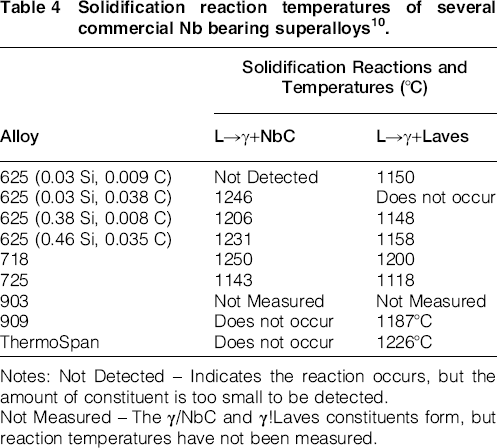
Notes: Not Detected – Indicates the reaction occurs, but the amount of constituent is too small to be detected.Not Measured – The γ/NbC and γ!Laves constituents form, but reaction temperatures have not been measured.
Knorovsky et al. conducted a detailed investigation of microstructural evolution in fusion welds on alloy 718. 82 In this alloy, the γ/Laves eutectic type constituent is the major microconstituent that forms, and γ/NbC forms in only small quantities. Thus, ignoring the small amount of γ/NbC, Knorovsky recognized that the alloy solidifies in a manner very similar to that of a binary system in which the solid solution primary γ phase can be treated as the ‘solvent’ and Nb as the ‘solute’ element. A pseudobinary solidification diagram was assembled from a combination of microchemical measurements and differential thermal analysis and is shown in Fig. 17. Points 1 and 2 were obtained from the nominal alloy composition, and solidus and liquidus temperatures. Point 3 represents the liquidus temperature and cell core composition. Points 5 and 6 represent the composition of the γ and Laves respectively in the γ/Laves eutectic type constituent. Note that point 5 represents the maximum solid solubility of Nb in γ for alloy 718 (9.3 wt-%). Point 7 is the solubility limit of Nb in the alloy 718 matrix as reported by Eiselstein. 83 Since Nb diffusion in γ is negligible during solidification, the Scheil equation can be used with this diagram to directly calculate how variations in Nb content will affect the final microstructure of alloy 718. It was demonstrated that the predictive capabilities of this diagram are quite accurate.
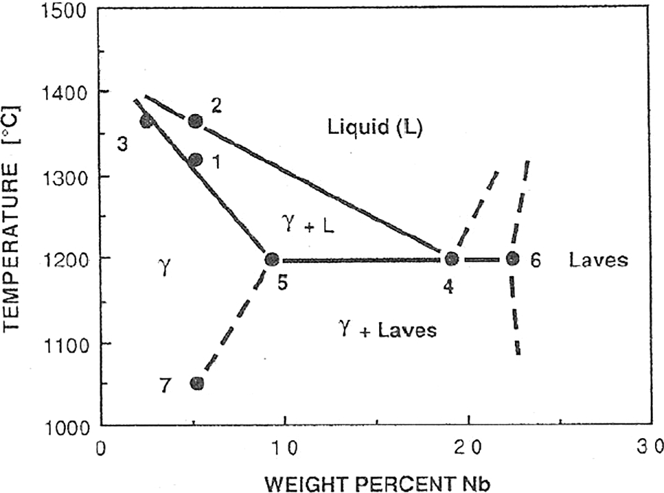
Pseudobinary solidification diagram established for alloy IN718 by combination of differential thermal analysis and electron microscopy techniques
Welding and weldability
Many welding issues need attention in addition to alloy design issues related to the development of Ni base superalloys. Welding and weldability of alloys of interest to AUSC technology will be discussed in part II of this paper. According to David, 2 ‘weldability is a measure of the ease with which a metal or an alloy can be welded or joined without degradation that is detrimental to the weldment microstructure or properties during or after welding and for the duration of its intended service’. As with any other family of alloys, some Ni base alloys are easily weldable, and some are not. For example, Inconel alloy 718 has good weldability but not very good high temperature strength, whereas Waspaloy has excellent high temperature strength but poor weldability. 84 The Ni base superalloys can be welded using conventional arc welding, electron beam and laser welding processes. The very fact that Ni base superalloys are complex alloys containing 10 or more elements including low melting constituents can inherently lead to cracking problems during welding.
Among the solid solution strengthened alloys, many exhibit a variety of cracking problems. Many are prone to solidification cracking, HAZ liquation cracking and ductility dip cracking. 10 In the case of precipitate hardened alloys in addition to the above mentioned cracking problems, the alloys are prone to strain age cracking. Many factors contribute to solidification cracking and HAZ liquation cracking (e.g. alloy composition, process and process variables, restraint). Solidification cracking is mainly due to the presence of low melting constituents and a wide solidification range. 85 Heat affected zone liquation cracking is due to grain boundary segregation or constitutional liquation. Alloys strengthened with Nb are susceptible to constitutional liquation cracking due to the melting of NbC precipitates in the grain boundaries. Judicious selection of filler metal with a narrow freezing range can reduce solidification cracking.
Ductility dip cracking is a sudden reduction in the ductility in the temperature range between solidus and 0.5 Ts. 10 It is a solid state phenomenon that occurs not only in Ni base superalloys but also in other materials, such as austenitic stainless steels and copper alloys. Strain age cracking is also a solid state cracking phenomenon that occurs in precipitation hardened alloys during reheat or PWHT. It is commonly observed in Ni base superalloys strengthened by Ni3 (Al, Ti,) precipitates. More detailed discussion of these phenomena and mechanisms will be presented later in this review.
Inconel alloy 718 is a good example of an alloy having these problems, and its development resulted in good ways to mitigate them. 86 Addition of Nb to the base composition revealed a slower aging response, which is attributed to the relatively poor crystallographic matching at the γ/γ″ interface that makes nucleation more difficult. The alloy exhibited strength levels equal to or better than Rene 41, Udimet 700 and Waspaloy. Weldability can be affected by addition of several elements. Addition of Nb has been found to decrease the resistance for solidification cracking. 87 Nb and Mo form carbides and can influence HAZ liquation cracking. S, P and B can increase the susceptibility for solidification cracking. B, if present in concentrations >0.003 wt-%, can increase HAZ liquation cracking.
Inconel alloy 718 contains a wide variety of phases [e.g. Ni3Nb (γ″), Laves phase, γ′, NbC, M6C]. The most significant behavior of this alloy is its reduced sensitivity to strain age cracking. This is mainly due to the sluggishness of the age hardening response in alloy 718 by Ni3Nb precipitates as opposed to very rapid precipitation of Ni3Al and Ni3Ti precipitates in other alloys (Fig. 18). The reduced sensitivity of the alloy to strain age cracking is attributable to the capability of the sluggish aging response to relax the yield strength level of residual stresses. 88
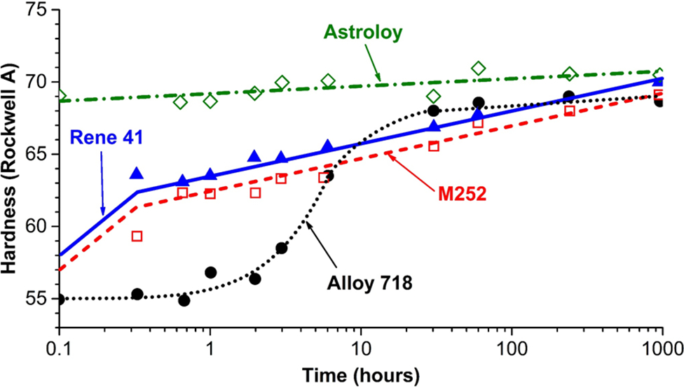
Age hardening response in alloy 718 by Ni3Nb precipitates compared with very rapid precipitation of Ni3Al and Ni3Ta precipitates in other alloys 88
During the past four decades, significant advances have been made in alloy design and processing to meet the increasing demands on turbine blades that operate at high temperatures.89–91 The breakthroughs include development of directionally solidified and single crystal alloys. Single crystal turbine blades are currently used in aircraft gas turbine engines.89–91 It is anticipated that superalloy single crystals will eventually find their way into land based gas turbine engines, increasing the efficiency of these engines. 92
The high cost of gas turbine blades and vanes has necessitated the repair of aircraft gas turbine engine components by welding as an alternative to the replacement of expensive components.93, 94 Significant advances have also been made in understanding the microstructure development in single crystal welds.95–97 Three obstacles must be overcome before Ni base alloy single crystals can be welded manually. First, the single crystallinity of the Ni base alloy is lost due to the formation of stray grains. Second, the Ni base superalloys are prone to cracking during welding, and the stray grain boundaries provide preferred crack propagation. Third, non-equilibrium solidification elemental partitioning and solid state transformation can yield microstructures that are not conducive to obtaining the desired high temperature properties. The weldability of single crystal PWA-1480 (Ni–12Ta–10.4Cr–5.3Co–4.8Al–4.1W–1.3Ti, in weight per cent) and CMSX4 (Ni–9Co–6.5Cr–6.5Ta–6W–5.6Al–1Ti–0.6Mo, in weight per cent) alloys was investigated by David et al. using laser and electron beam welding processes.98–101 The alloys showed severe cracking tendencies in the fusion zone that were identified as solidification cracks. Figure 19 shows the dendritic nature of a crack surface in a PWA-1480 weld. The weld must have cracked when it was ∼80% solid and 20% liquid. The opening of the crack drained most of the liquid, revealing a well developed and well defined dendritic structure. The dendrites were all aligned along the [100] direction. Successful welds were made using a 500°C preheat. A critical issue here was that the welds contained stray grains in the fusion zone. To explain the stray grain formation, Vitek et al. 102 used the theories of Kurz et al.103, 104 on dendrite tip undercooling, growth and constitutional supercooling ahead of the advancing solidification front. The theory agrees with the experimental results and provides a basis for optimisation of the welding conditions so as to yield welds that are free of stray grains. The mechanism of stray grain formation and their elimination are discussed in detail in the literature. 102
Crack surface in PWA-1480 weld, showing dendritic nature of crack [courtesy of S. A. David]
Weld cracking in nickel base super alloys
Various types of cracking observed in welds during welding or heat treatment that was mentioned in the earlier section will be addressed in detail.
Fusion zone solidification cracking
Weld solidification cracking in the fusion zone of Ni base alloys has been the subject of considerable investigation, and the mechanism is generally well understood. As with other alloy systems, cracks can form during the terminal stages of solidification when liquid films are distributed along solidification grain boundaries and, in some cases, interdendritic sites. At this stage, shrinkage strains across the partially solidified boundaries can become appreciable. If the terminal liquid is distributed along the boundaries as a continuous film, the strains cannot be accommodated and the boundaries separate to form a crack.
Susceptibility to weld solidification cracking is a function of both metallurgical factors and the level of local strain present at the end of solidification. In terms of metallurgical factors, it is well established that the solidification temperature range as well as the amount and distribution of the interfacial terminal liquid are the primary factors that control solidification cracking susceptibility of Ni base alloys.66, 69, 70 Solute redistribution plays an important role in solidification cracking as it affects the solidification temperature range and amount of terminal liquid. The solidification temperature range controls the size of the solid+liquid crack susceptible region that surrounds the liquid weld pool. A relatively wide solidification temperature range will produce a correspondingly large solid+liquid crack susceptible region, thus increasing cracking susceptibility. The actual distance a solidification crack propagates through the mushy zone depends on the distribution of terminal liquid that exists near the end of the solid+liquid region and the level of local strain present. The distribution of liquid near the end of the mushy zone is, in turn, controlled by the amount of terminal liquid and solid/liquid surface tension. When the amount of terminal liquid is moderate, between ∼1 to 10 vol.-%24, 65 and/or the surface tension is low, the liquid tends to wet the boundary and forms a continuous film. This type of morphology is most detrimental as it interferes with the formation of solid/solid boundaries, thus reducing the ability of the material to accommodate strain. In contrast, a small amount of terminal liquid, generally less than ∼1 vol.-%, that exhibits a high surface tension with the solid will often exist as isolated globules and promote solid/solid bridging, thereby reducing cracking tendency. When the amount of terminal liquid is high (greater than ∼10 vol.-%), it can often flow into the cracks and provide a ‘crack healing’ effect.105, 106 For a given alloy system, the solidification temperature range and amount of terminal liquid are controlled primarily by composition.
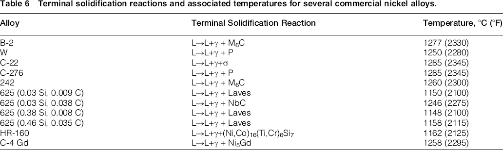
The relative cracking susceptibility for a wide range of Ni alloys has recently been reviewed and is summarized in Table 5 based on available Varestraint results. 10 In this table, alloys at the top of the list with low values of maximum crack length exhibit relatively good resistance to solidification cracking. The cracking resistance decreases for alloys toward the bottom of the list with higher maximum crack length values. For alloys that generally solidify as single phase austenite with no appreciable intermetallic and/or carbide formation at the end of solidification, the cracking susceptibility can be minimized by limiting the amount of tramp elements such as P and S that tend to extend the solidification temperature range. Boron can have a similar effect, although this element is sometimes deliberately added for improved creep strength. In more highly alloyed solid solution strengthened alloys, the formation of carbide and/or intermetallic phases at the terminal stages of solidification generally controls solidification cracking susceptibility. In general, these phases are the product of a eutectic reaction that occurs at the end of solidification. This eutectic reaction occurs at a lower temperature than the alloy solidus and expands the solidification temperature range, making the alloy more susceptible to cracking. Table 6 summarizes the terminal reactions and associated reaction temperatures observed in several commercial alloys. These data, taken in combination with available Varestraint weldability results, are useful for identifying general trends between alloy composition and weldability. A more detailed discussion of these effects is provided in Ref. 10.
Approximate relative ranking of fusion zone cracking susceptibility based on Varestraint data 10 (note: references in the ‘Reference’ column are provided below this table).

[1] Rowe, M. D., Ishwar, V. R., and Klarstrom, D. L. 2006. Properties, weldability, and applications of modern wrought heat resistant alloys for aerospace and power generation industries, Transactions of ASME, 128: 354-361.[2] Rowe, M. D., Crook, P., and Hoback, G. L. 2003. Weldability of a corrosion resistant Ni-Cr-Mo-Cu alloy, Welding Journal, 82(11): 313s-320s.[3] Gallagher, M. 2007. Unpublished research performed at The Ohio State University.[4] J. C. Lippold, J. Sowards, B. T. Alexandrov, G. Murray, and A. J. Ramirez, 2007. Weld solidification cracking in Ni-base alloys, 2 nd International Workshop on Hot Cracking, Berlin, March 2007, Springer-Verlag.[5] DuPont, J. N., Michael, J. R., and Newbury, B. D. 1999. Welding metallurgy of alloy HR-160, Welding Journal, 78(12): 408s-414s.
Terminal solidification reactions and associated temperatures for several commercial nickel alloys.
Heat affected zone liquation cracking
During welding, the base metal just adjacent to the fusion zone will experience a range of peak temperatures that is between the liquidus and effective (non-equilibrium) solidus temperature of the alloy. The microstructure within this region will therefore undergo partial melting and is described as the partially melted zone (PMZ) region of the HAZ. Liquation cracking can occur in the PMZ in Ni base alloys when the liquid within the locally melted region cannot sustain the applied strain and forms a crack, usually along a grain boundary. The tendency for HAZ grain boundary liquation is increased with welding processes that are made at high heat input.
Heat affected zone liquation cracking in Ni alloys can be associated with several types of localized melting, including localized melting at the grain boundaries, constitutional liquation of secondary phases 10 and localized melting of eutectic constituents. For alloys that are single phase, the segregation of alloy, and impurity elements (S, P, and B), to the grain boundaries can cause a local depression of the melting temperature and promote the formation of continuous liquid films along these boundaries.107–109 Thus, the grain boundaries typically undergo some degree of liquation within the PMZ of single phase materials. It has been suggested that grain boundary segregation can be increased during grain growth within the HAZ as solute and impurity elements are swept into and accumulate in the migrating boundary. 107 Subsequent solidification of the solute rich grain boundaries can often be observed in the PMZ as thick boundaries when the microstructure is appropriately polished and etched. An example of this segregation and associated cracking is shown for alloy 617 in Fig. 20. 45
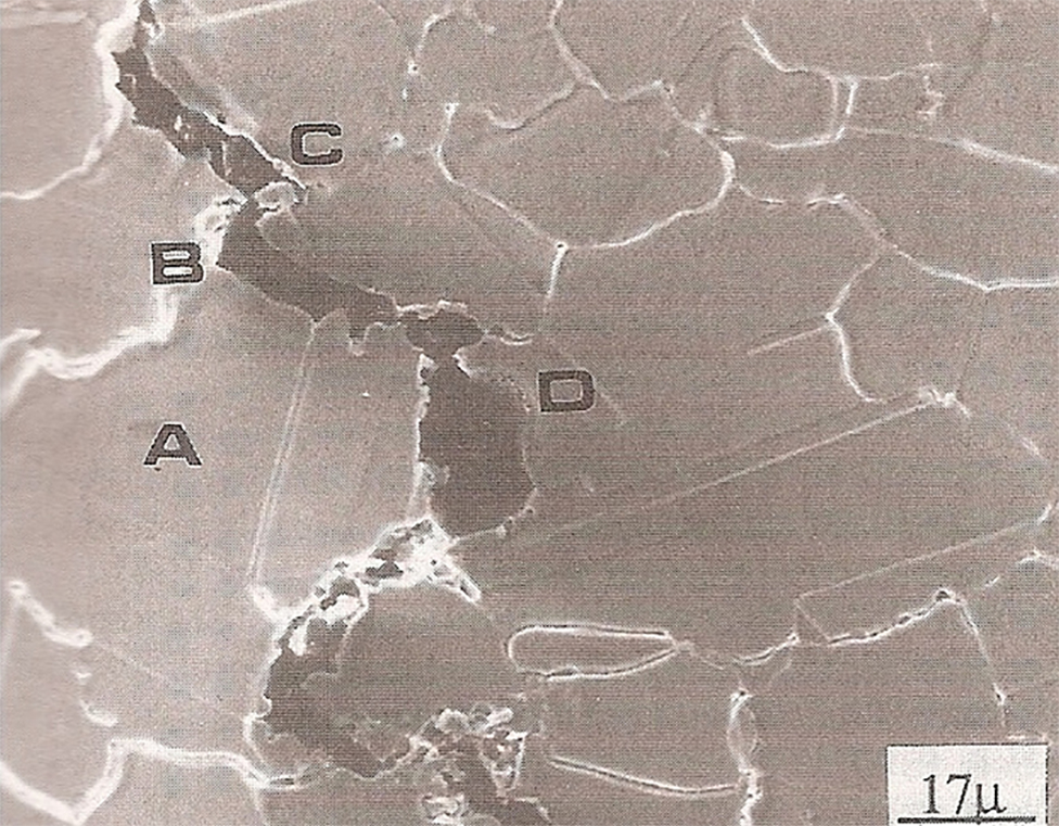
Example of HAZ liquation cracking in alloy 617 110
Heat affected zone liquation cracking associated with constitutional liquation can occur in Ni base alloys that contain secondary constituents such intermetallics, carbides or TCP phases.110–112 In this case, the rapid heating associated with the weld thermal cycle does not permit sufficient time for dissolution of the secondary phase within the matrix. Upon heating above the eutectic temperature, the secondary phase reacts with the matrix to form an interfacial liquid film that is at the eutectic composition. This type of liquation has been observed at carbides and intermetallic phases in a number of Ni base alloys, including the precipitation strengthened alloys Udiment 700, Waspaloy and alloy 718, and the solid solution strengthened alloys Hastelloy X and alloy 625.113–117 This mechanism is more common in precipitation strengthened alloys.
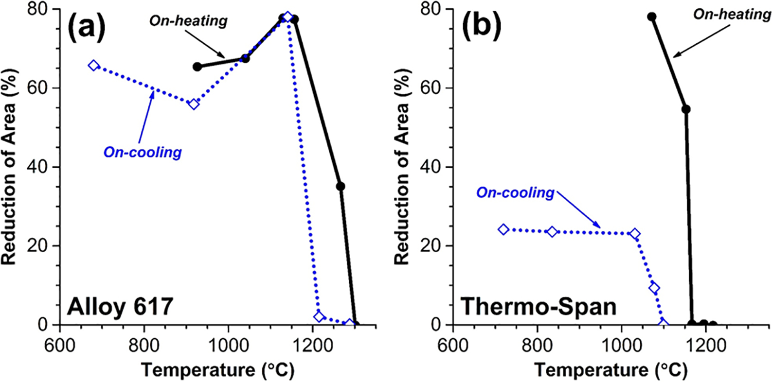
Most solid solution Ni alloys are designed to be single phase with all alloying elements in solution. Thus, the cracking susceptibility is generally lower than that of precipitation strengthened alloys. An example of this is shown in Fig. 21, which compares Gleeble hot ductility results for a solid solution strengthened alloy (alloy 617) with the precipitation strengthened alloy Thermo-Span.110, 118 The zero ductility range (ZDR) is typically used as an indicator of HAZ cracking susceptibility in these tests. This parameter is given by the difference between the nil strength temperature and the temperature at which the alloy begins to recover ductility upon cooling from the nil strength temperature. Alloys with wider ZDR values exhibit more extensive liquation and associated cracking susceptibility. Alloy 617 exhibits a ZDR of ∼100°C, while the Thermo-Span alloy has a ZDR nearly twice that value at ∼190°C. In addition, note that the solid solution strengthened alloy regains essentially all its ductility during cooling, while ductility for the cooling portion of the precipitation hardened alloy is significantly less than the ductility exhibited during heating.
Eutectic melting and constitutional liquation can occur in alloys that are classified as solid solution strengthened materials, particularly those with Nb and Ti additions. It is well known that NbC and TiC are subject to constitutional liquation in the austenite matrix.110, 115, 117 For example, the base metal of alloy 625 contains NbC that can result in constitutional liquation and subsequent HAZ liquation cracking. In some alloys, residual eutectic and secondary constituents can be remnant from the original casting process when the post-casting and/or thermomechanical working treatments are not sufficient for complete dissolution of the secondary constituent. In these alloys, it is the condition of the starting base metal microstructure, rather than the general alloy classification, that dictates the susceptibility to HAZ liquation cracking.
The influence P, S and B on liquation cracking in Ni alloys is similar to that of fusion zone solidification cracking, where these elements are known to be particularly harmful. Phosphorous is generally the least deleterious and B the most detrimental, with the role of S mainly being intermediate. These elements all aggravate cracking by segregating to the grain boundary, resulting in liquid films that persist to low temperatures. Thus, impurity element concentrations should minimized to avoid cracking. In contrast, B is occasionally intentionally added to some Ni base alloys to improve creep properties, and it may be necessary to balance the benefit of improved creep resistance with a potential degradation in weldability.
The starting base metal microstructure also has an important influence on cracking susceptibility. In general, base metals that have been homogenized and exhibit a fine grain size in the solution annealed condition have reduced susceptibility to cracking. The fine grain size is beneficial because it creates more grain boundary area, reducing the unit strain per grain boundary and requiring more liquid to wet the boundaries. It should be noted, however, that use of a fine grained material for avoiding liquation cracking may not always be possible, as it may have an adverse effect on applications at high operating temperatures where creep resistance is important. The homogenisation is beneficial since it reduces remnant microsegregation that can aggravate cracking in regions where the solute content is locally high. Similarly, solution treatments are helpful at dissolving secondary phases that can cause localized melting by either constitutional liquation or direct eutectic melting. Based on these considerations, it is apparent that cast Ni alloys are generally more susceptible to cracking than their wrought counterparts.
Strain age cracking
Strain age cracking, also known as stress relief cracking, stress relaxation cracking or service induced cracking, is solid state cracking phenomenon commonly observed in precipitation strengthened austenitic steels, ferritic steels and Ni base alloys. This cracking mechanism often occurs in γ′ strengthened materials during PWHT (such as during a post-weld aging treatment), but it has been documented in solid solution strengthened alloys after several thousand hours after service exposure. 1 These in service failures are typically documented as stress relaxation cracking and will be discussed in detail in part II of this review due to their importance to AUSC applications. Sensitivity of nickel base alloys to strain age cracking depends on several factors, including composition, grain size, welding residual stress, PWHT (or service exposure including both the temperature and the time), base metal condition and welding procedures.
Often, strain age cracking is observed in the HAZ, very close to the fusion line and sometimes in the weld metal. These cracks are always intergranular. Figure 22a and b shows intergranular strain age cracking in a simulated HAZ of Waspalloy and fracture morphology of strain age cracking in alloy 718C respectively. 10 Cracking is a result of an inherently low creep ductility in the HAZ that is insufficient to relax the welding residual stresses by strain.10, 119–121 In precipitation strengthened alloys such as Ni base superalloys with γ′ Ni3 (Al, Ti) precipitates, a strain intolerant microstructure can form during aging as the γ′ forms intragranularly and preferentially increases the strength within the grain. Furthermore, simultaneous grain boundary weakening can occur due to the formation of precipitate free zones along the grain boundary and weakening of the grain boundaries. 122
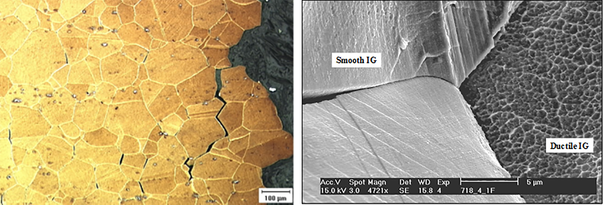
a intergranular strain age cracking in simulated HAZ of waspalloy; b fracture morphology of strain age crack in alloy 718C 10
There are several other reasons given for the low ductility in the HAZ. They include embrittlement of the grain boundary by oxygen during PWHT123, 124 or a change in the mode of deformation from transgranular slip to grain boundary sliding. In these alloys, the rate of precipitation controls the cracking. In alloys such as Rene 42 and M-252, the rate of precipitation is extremely rapid after solutionising and aging. However, for alloy 718, which contains a deliberate Nb addition, the precipitation of Ni3Nb is more sluggish and allows the material to relax welding residual stresses during the heat treatment, thereby greatly reducing the susceptibility to strain age cracking.
The propensity for strain age cracking depends primarily on composition. Prager et al. 121 have shown that Al+Ti content provides stronger and more rapid precipitation of γ ′ during PWHT and solutionising. Figure 23 shows relationship between Al and Ti on the weldability of Ni base superalloy.125, 126 Alloys with higher Al+Ti content are more susceptible strain age cracking. However, this diagram does not take into account thermomechanical processing or heat treatment procedures. The recently developed diagram shown in Fig. 24 127 is based on welding process, speed and procedures. Figure 24 shows one such diagram for alloy 718. Using Waspalloy and alloy 718, Duvall and Owczarski 127 showed that the susceptibility for cracking in the alloy 718 HAZ during PWHT follows a C curve behavior. Compared to the Waspalloy C curve, the C curve for alloy 718 was displaced to the right for larger time, indicating that alloy 718 was more resistant to strain age cracking than Waspalloy was. 127 Sidhu et al. 128 have designed filler metals with varying Al+Ti and have shown that the cracking susceptibility of IN738LC was reduced by using age hardenable filler metal with less Al+Ti than that in the base metal. The PWHT cracking resistance in IN738LC was further improved by using the filler metal in conjunction with heat treatment. 129
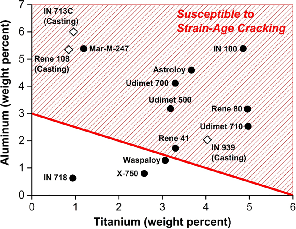
Relationship between estimated weldability and Al and Ti content 121
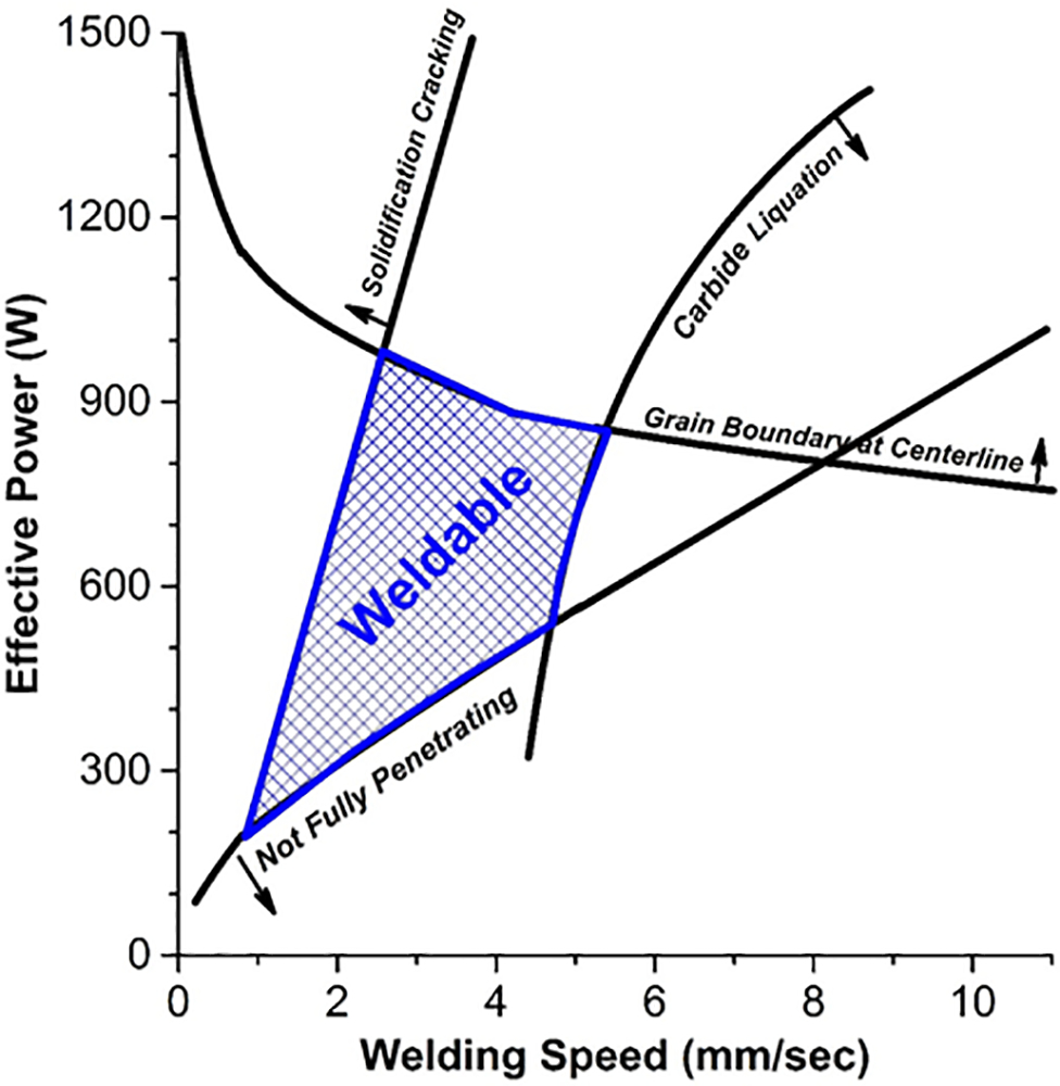
GTA weldability process diagram for IN 718 plate 127
Segregation of tramp elements such as S, P, Sn, Sb and others, including B, Mn or Al, can promote decohesion and cracking in the boundaries. Cavities are supposed to nucleate at sites where S segregates. Grain boundary precipitates such as carbides and intermetallics can also promote strain age cracking. Fine grained alloys have been found to be more resistant to strain age cracking than coarse grained alloys. Fine grained materials have a greater grain boundary area, and so it can provide for grain boundary sliding.
Reduced heat input during welding and preheat can reduce the susceptibility for strain age cracking. King et al. 129 have found that higher preheat (705 to 925°C) prevented cracking during PWHT. Heat treating has been used before cracking to avoid strain age cracking. These treatments generally over-age the alloy and allow stress relaxation to take place easily. The heat treatment is followed by a solution anneal and aging treatment to restore the properties. For alloys with very high volume percentage of γ′, such as 713C, a weld preheat of slightly above the γ′ precipitation temperature is used. The preheat temperature is maintained throughout the welding operation and is increased to solutionising temperatures.
An important component of strain age cracking is the presence of residual stresses in the weldment. Residual stresses in the weldment are elastic in nature and can reach yield strength.130–132 They develop due to phase transformations (coherent precipitation of γ′) as well as several other sources,130–132 such as solidification shrinkage, thermal conditions, heat input during welding, a difference in coefficient of thermal expansion and mechanical constraints due to large differences in thickness. There are many different techniques to quantify residual stresses in weldments, including destructive and non-destructive methods. Commonly used destructive techniques include hole drilling, contour method and slitting. Nondestructive methods include testing such as X-ray diffraction (typically for surface measurements) and neutron diffraction (through thickness measurements). Measurement of welding residual stresses using neutron diffraction can be complicated because the activation risk associated with alloying additions such as Co.130–132
Many theories have been put forth and testing methodologies have been developed to understand strain age cracking. Still, the underlying mechanism has yet to be determined. This is mainly due to the lack of a holistic testing methodology that gives a definitive evaluation of cracking susceptibility. Most of the current tests, such as Gleeble, stress to fracture and the patch test, are not applicable since they do not simulate real conditions of stress development during cooling of the weld metal and stress relaxation subsequent to PWHT. Kuhn et al. 133 have developed a four-point bend relaxation test based on the principles of the three-point bend test developed by Van Wortel. 134 The method was used to characterize the cracking susceptibility of welded joints in alloy 617B. All as welded joints failed by interdendritic fractures in the weld metal, and the fracture location corresponded to maximum hardness, but the heat treated specimens did not crack during the test. However, the authors conclude that to ensure ‘relaxation’ cracking during the test, a mechanical load had to be superimposed on the specimen, thus questioning the validity of the test method to fully characterize a materials tendency to strain age cracking. Norton and Lippold 135 have developed a Gleeble thermomechanical simulation based test to characterize stress relief cracking that firmly demonstrates the conditions that exist during strain age cracking.
In spite of numerous studies and publications, strain age cracking is still not very well understood, and a great deal needs to be done as to determining the accurate measurement and the underpinning mechanisms of strain age susceptibility.
Prognosis
Efforts will continue globally to provide clean and affordable energy with low carbon foot print. This can be realized through AUSC coal fired power plants operating at high temperatures and pressure at higher operating efficiencies. Nickel base superalloys are one of the classes of materials considered for applications where the temperature is >700°C. Nickel base alloys with other alloying additions are very expensive. Efforts are continuing to develop new nickel base alloys with comparable properties to the currently suggested alloys at lower cost. The prognosis for such a development looks encouraging. Tancret and Bhadeshia have developed Gaussian process model to suggest new nickel base alloys that possess required mechanical properties with stable microstructures.136–138 Gaussian process model is a ‘non-linear multidimensional statistical regression analysis’.
Ni base alloys are highly complex systems that typically contain 10 or more elements in order to provide the required strength levels and corrosion resistance for advanced power plants. The unique properties can generally be attributed to the relatively high solubility of many elements in Ni and, for precipitation strengthened alloys, the ability to form the γ′ and γ″ phases via heat treatment. It is important to note that the final balance of properties is typical achieved by carefully designed and controlled heat treatment thermal cycles. Welding thermal cycles, in contrast, are significantly more rapid and produce significant changes to the microstructure in both the fusion zone and HAZ regions. These microstructural changes often promote appreciable loss of strength and/or corrosion resistance and can also lead to the formation of various cracking defects. The second part of this review article will provide a detailed discussion regarding the weldability of the specific candidate materials as well as an assessment of weldment performance including specific guidance for minimising property losses in the weld. This information will be useful for successful implementation of Ni alloys whenever welding is used as a fabrication step during construction.
Acknowledgements
The authors wish to acknowledge Dr J. Chen (Oak Ridge National Laboratory) for his valuable time and assistance in preparing the manuscript. We also would like to thank Professor H. K. D. H. Bhadeshia for his review and valuable comments.
Footnotes
a
Higher heating value (HHV) includes latent heat of vaporization of water in the combustion of coal. In this paper, plant efficiency is always noted in terms of HHV. Similarly, the units of concentration are always in weight percent (wt-%).
b
Solubility strictly depends on which phase the γ′ is in contact with.
c
These equations are for one-dimensional solidification, i.e. lat interface ≠ dendrite.