
Abstract
In this paper, the effect of pin features and orientation/placement of the materials on advancing side were investigated for friction stir welding (FSW) of dissimilar aluminum alloys AA2050 and AA6061. Pins for FSW were produced with a 2·12 mm pitch thread having three flats/flutes. Three sets of rotational speed/welding speed were used to perform a series of welds in a butt joint arrangement. The results show that, joint quality, process response variables and welding temperature are highly affected by pin features and material orientation in FSW. Defect free joints with effective material transportation in the weld nugget zone were obtained when welding was performed with AA2050 on the advancing side. The tool also encounters less in plane reaction force for welding with 2050 on the advancing side. Pin with thread+3 flats produces quality welds at low rotational and travel speed regardless of the location of alloys on advancing or retreating side.
Keywords
Introduction
Dissimilar material friction stir welding (FSW) has received increasing interest, since aerospace and automotive industries adopted this process for some applications in order to eliminate mechanical fastening such as riveted or bolted joints.1, 2 The eventual purpose is to improve fuel efficiency by reducing weight of structures. Many combinations of dissimilar aluminum alloys (precipitate hardened and/or solution hardened) have been successfully joined using FSW.3–19 It is noted that differential material properties at the abutting interface is a critical issue in dissimilar material welds. Therefore, the choice of suitable welding parameters, tool features and alloy placement in advancing/retreating side have significant influence on obtaining the best possible properties in bimaterial friction stir welded parts.
Numerous studies have been devoted to understand the material flow in the dissimilar material FSW in butt weld arrangement using different tool geometries.3, 7, 8, 15, 20 Aval and co-workers 9 studied the tool geometry effect on the mechanical and microstructural properties for dissimilar friction stir butt welding of AA5086-O and AA6061-T6 with 5086 on the advancing side. They reported that a tool with a concave shoulder and tapered unthreaded/smooth pin with three grooves generated higher heat (as observed from measured peak temperature at 10 mm from weld centreline, both in advancing and retreating sides) relative to a tool with a cylindrical smooth or threaded pin with grooves. At higher rotational speed and/or lower welding speed, they observed substantial material movement as evidenced from complex features in macro cross-sections and magnesium distribution in the nugget zone from energy dispersive X-ray analysis. Da Silva et al. studied the material flow in the friction stir butt welding of dissimilar alloy AA2024-T3 and AA7075-T6 with 7075 on the advancing side using a threaded pin. 7 They observed an unstable rotational flow around the threaded pin with a formation of cavities behind the pin. This instability in material flow was evident from the micrographs of longitudinal sections of the weld. The cross-sections were made with the pin still embedded in the weld at the weld finish. Full contact of the pin thread with the material was observed on the leading edge, whereas a gap in the interface between the tool thread and weld material was observed at the trailing edge, resulting in cavity formation on the advancing side. With higher rotational speed, onion ring structures were also observed. Park et al. also examined the effect of placing AA 6061 and AA5052 on both advancing and retreating sides and reported the comparison of mixing state of the nugget zone along with weld properties. 17 When AA5052 was placed on the advancing side, more uniform distribution of magnesium in the weld nugget zone was observed. This was evident from their electron probe microanalysis. Dissimilar FSW was also investigated by Peel et al. by exchanging the AA5083 and AA6082 on both advancing and retreating sides. 18 A higher interfacial disruption was evident from macrographs at higher rotational speed when AA5083 was placed on the advancing side. Formation of voids was also reported when 6082 was placed on the advancing side at low rotational speed.
In essence, there is a common theme observed in reviewed literature: with high heat input resulting from high rotational speed, the effect of the alloy placement (advancing or retreating side) in bimaterial FSW might be minimised. However, delaminations or cracks at the weld surface were also reported at higher rotational speed bimaterial welding presumably caused by incipient local melting, 3 so the high heat input solution is not always feasible. On the other hand, controversies exist regarding which alloy of a dissimilar metal pair should be placed on the advancing (or retreating) side. Some works on dissimilar material FSW have reported that the quality of welds can be improved by placing the alloy with lower strength on the advancing side,6, 12, 13 while other studies indicated that weld properties were significantly improved by placing the stronger material on the advancing side.8, 17–19 Moreover, there is a complex interaction of material flow with tool geometries and features for a given set of process parameters. Some references can be found in the literatures that acknowledge that the weldability and flowability of material result from the combination of the effects of alloy placement on the advancing/retreating side, FSW parameters and pin features. A very recent study was made by Izadi et al. 8 They observed the effect of the pin features on bimaterial FSW of AA2024 and AA6061 in both lap and butt weld arrangement with different pin features. In the case of lap welding with a grooved pin, the horizontal interface of the lapping surface was not disrupted after welding, which they deemed to result from poor vertical intermixing. On the other hand, promotion of vertical intermixing was reported when a flatted pin was employed in lap welds as evident from micrographs and energy dispersive X-ray mapping of Cu. Moreover, at very low welding speed (33 mm min− i), a threaded only pin resulted in fine scale intermixed lamella in the nugget zone regardless of the position of either alloy on the advancing/ retreating side. 8
In the study reported on here, dissimilar metal FSW of AA2050 and AA6061 was examined in a butt joint configuration. Distribution of the two alloys in the nugget zone was examined by metallographic sectioning of welds made using different pin features (flats/flutes) and process control parameters. The effects of the placement of the alloys (i.e. advancing and retreating sides), pin features and control parameters on the weld response variables such as in plane reactions on pin, torque, power and temperature are reported and discussed. The aim of this study is to understand how these parameters affect the process in bimaterial FSW.
Materials and experimental details
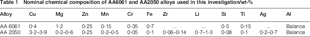
Precipitation hardened aluminum alloys of the 2xxx and 6xxx series are frequently joined together using FSW.4, 6, 8, 10, 14, 15, 19 There are obvious property differences of these two aluminum alloy types, where 2xxx is relatively high strength and 6xxx is medium strength and more ductile material with higher thermal conductivity. AA2050 has some outstanding properties, such as higher specific strength, fairly easy weldability using FSW, better mechanical strength of welded parts than high strength 7xxx series aluminum alloys and weight benefit in terms of fuel efficiency for aircraft. 21 The main hardening precipitate in AA2050 is T1 (Al2CuLi). Other alloying elements, such as Mn and Zr, are added to prevent static recrystallisation during standard plate processing. Silver (Ag), in the presence of Mg enhances the aging kinetics of AA2050. On the other hand, medium strength aluminum alloy AA6061 has very good weldability, formability and corrosion resistance compared with many other aluminum alloys. Mg2Si is the main hardening precipitate in AA6061. Friction stir butt welds of dissimilar materials were performed on AA6061-T651 (25·4 mm thick) and AA2050-T4 (20 mm thick). Nominal chemical compositions of these two alloys are shown in Table 1.
Nominal chemical composition of AA6061 and AA2050 alloys used in this investigation/wt-%
The welding tools for these dissimilar butt joints were made of H13 steel. Tool shoulder and pin geometries were kept constant, while pin features were varied. This variation was facilitated by constructing the tool in two pieces with separate pins and an unvarying shank with the constant geometry shoulder. Tool shoulder dimensions are 25·4 mm diameter, single scroll with a scroll pitch of 2·54 mm. The conical pins were produced with an 8° taper angle. The pin length was 12·7 mm, and the maximum diameter was 15·9 mm. These pin dimensions enable welding under a wide range of process parameters. Pins were fabricated with four different combinations of same thread, but different thread interruptions: (i) right hand helical thread (2·12 mm pitch/12 thread per inch), termed as threaded only, (ii) the same thread with the addition of three flats inserted at 120° angle from each other, termed thread+3 flats, (iii) the same thread with the addition of three co-flow flutes at 120° angle each, with same orientation as threads: termed as thread+3 co-flow flutes and (iv) the same thread with three counter flow flutes at 120° angle each, with the orientation opposite to that of thread: termed as thread+3 counter flow flutes. The pitch of the flutes was 76·2 mm. Since the root depth of thread was 1·27 mm, to maintain consistent dimension of pin with flats or flutes, depth and width of the flat/flute were 1·35 and 6·4 mm respectively. It is anticipated that the co-flow flutes will increase the downward motion of material due to tool rotation while the counter flow flutes should have the opposite effect.
Both 6061 and 2050 plates were cut to size using a radial saw and machined to obtain equal thickness of 20 mm. Predrilled holes were made at the starting point of welds to ease plunging. Plates were aligned and clamped by finger clamps on a steel back plate. Welding was performed on the USC FSW Process Development System using forge force control mode. For each weld parameter set, forge force along the z axis was adjusted to maintain similar depth of penetration based on the observed contact condition between the shoulder and the top surface of the welded plate. Series of welds were made with three sets of rotational and welding speed: 150 rev min− 1–101 mm min− 1, 300 rev min− 1–203 mm min− 1 and 300 rev min− 1–406 mm min− 1. These parameters were selected based on previous experience in dissimilar material FSW with the criteria that first two parameter sets have the same advance per revolution (APR = 0·67 mm). All the welds were performed at 0° spindle tilt angle. In plane reaction forces and spindle torque were recorded for all welds. Weld power was calculated from torque and revolutions per minute. Temperature during welding was monitored and recorded using a k type thermocouple spot welded into the pins at mid depth in between the shoulder and the pin tip along the axis of rotation.
Metallographic specimens were cut using an abrasive water jet at a location of 125 mm from the start of each weld. Grinding and polishing were performed according to standard metallographic procedure for Al alloys. Specimens were chemically etched using Keller's reagent (2·5% HNO3, 1·5% HCl, 1% HF and balance distilled water) for macro- and microstructural observation. Etching time was adjusted for microstructural evaluation of the two alloys: relatively short time for AA2050 (10–15 s) and longer time for AA 6061(90–120 s).
Results and discussion
Macroscale cross-sections of bimaterial welds
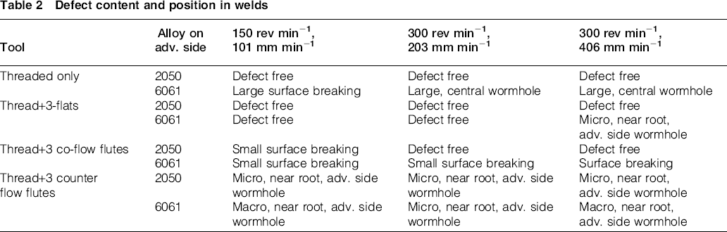
Figure 1 shows the macrographs of the cross-sections for dissimilar metal welds for threaded only pin (Fig. 1a), thread+3 flats pin (Fig. 1b), thread+3 co-flow flutes pin (Fig. 1c) and thread+3 counter flow flutes pin (Fig. 1d) respectively. The 6061 appears dark and 2050 appears light in these macroscale cross-sections. Figure 1 clearly indicates that bimaterial weldability is strongly dependent on alloy placement and pin profile as macroscopic defects were observed only when 6061 was placed on the advancing side. No macro size defects were observed in FSW joints when 2050 was placed on the advancing side, regardless of the variation in pin features or weld parameters. Table 2 summarises the defect content in all of the welds. The types of defects have been characterised as (i) large or macroscopic wormhole defects (surface breaking for one case), (ii) microscopic, near the root, advancing side defects and (iii) small surface breaking defects (advancing side). Figure 2 shows examples of microscale defects. It is apparent that the pin features definitely affect FSW joint quality, including existence, severity and position of defects. Defects produced using the threaded only pin with various welding parameters were large and almost centrally located in the weld nugget. The threaded only pin did not produce defects when 2050 was placed on the advancing side. The thread+flats pin produced microscale near root advancing side defects for only one condition: 6061 on the advancing side and 300 rev min− 1, 406 mm min− 1 welding. The thread+co-flow flute pin resulted in small, crown surface breaking defects on the advancing side for all 6061 on the advancing side welds and for one condition with 2050 on the advancing side. The thread+counter flow flute pin produced small, near root, advancing side defects under all six conditions. The defect locations produced by the co- and counter flow flute pins are consistent with expectation: it is anticipated that the counter flow flutes will pull the material away from the root region resulting (under some circumstances) in near root defects. Conversely, the co-flow flutes will push additional material downward potentially starving the crown region of material and leading to the surface breaking defects that were observed.
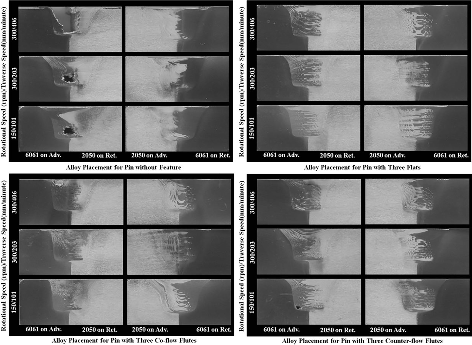
Macro cross-sections of bimaterial FSW of AA2050 and AA6061 using different pin features and weld parameters with alloy placement
Defect content and position in welds
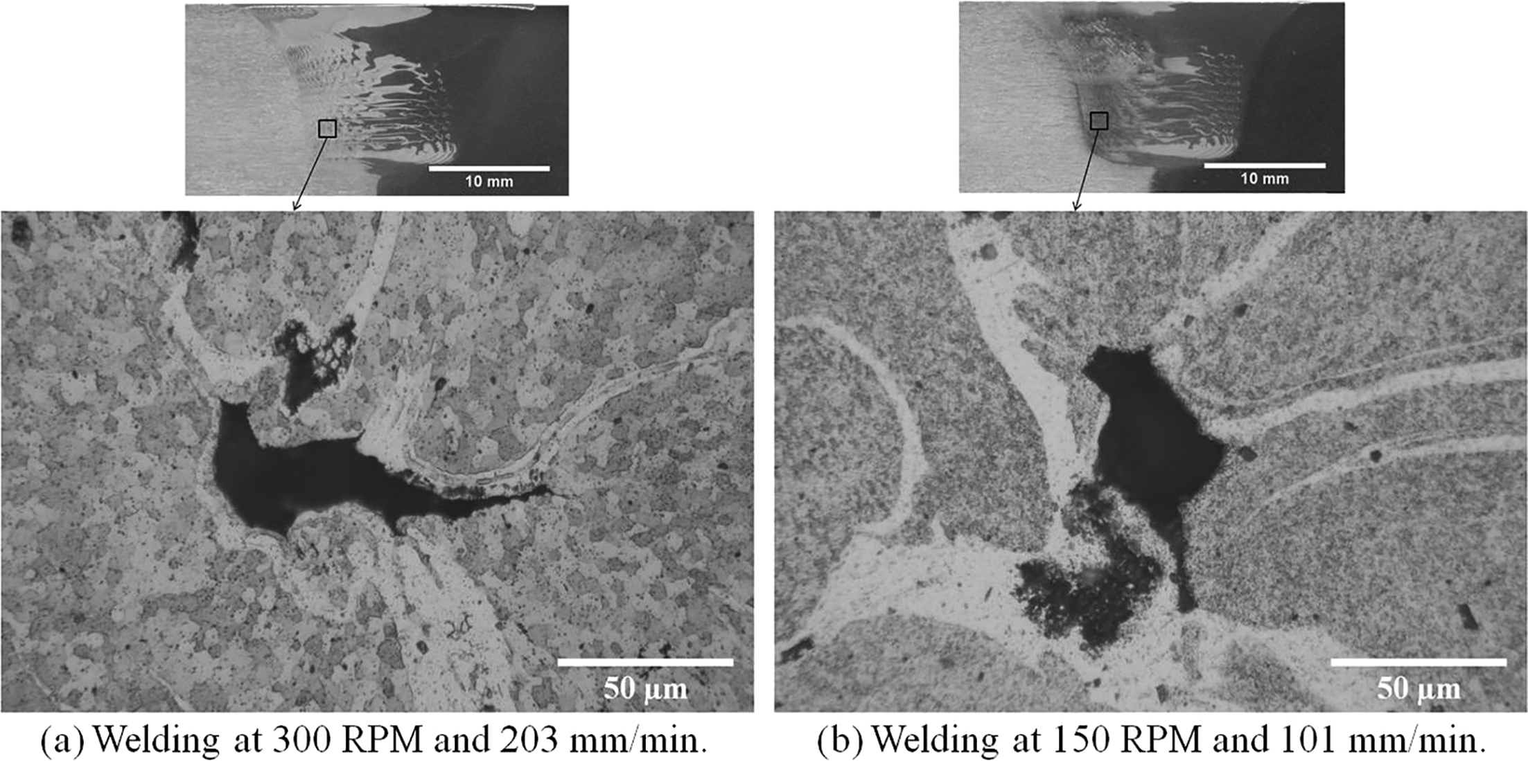
Microscopic defects in weld cross-sections at advancing side of nugget zone during FSW with pin having thread+3 counter flow flutes for different welding parameters
Figure 1 suggests that movement of material across the weld centreline and intermixing of the two alloys occurred with all tool types, but the amount of such movement and the level of intermixing were noticeably less for the threaded only tool. Alloy 6061/2050 interface lengths for each weld were determined by image analysis on scanned cross-sections by detecting the change in etching characteristics. The results are shown in Fig. 3. The results for each pin type are normalised by the result for the pin with the largest interface length, all welding parameters and alloy positions are lumped together and only pin type is considered as a variable. Obviously, flats and counter flow flutes produce the highest level of intermixing while the thread only pins produce the least. It was also noticed from the weld macrostructural observation that the region of recrystallised material under all of the pins was higher when AA2050 was placed on the advancing side compared to AA6061 on the advancing side. The measured average depth of recrystallisation beneath the pin was 0·46 ± 0·22 mm in the case of AA6061 on the advancing side, whereas with AA2050 on the advancing side the average deformation zone depth was measured as 1·36 ± 0·2 mm. Finally, the flow patterns in the welds were made with different parameters, but same weld pitch or APR (150 rev min− 1/101 mm min− 1, and 300 rev min− 1/203 mm min− 1) are not identical for a given tool and alloy combination. This indicates that the flow is not kinematically determined by the tool geometry and APR even when the defects are absent: welding power input and its effect on temperature and hence the flow stresses of materials must also be factors.
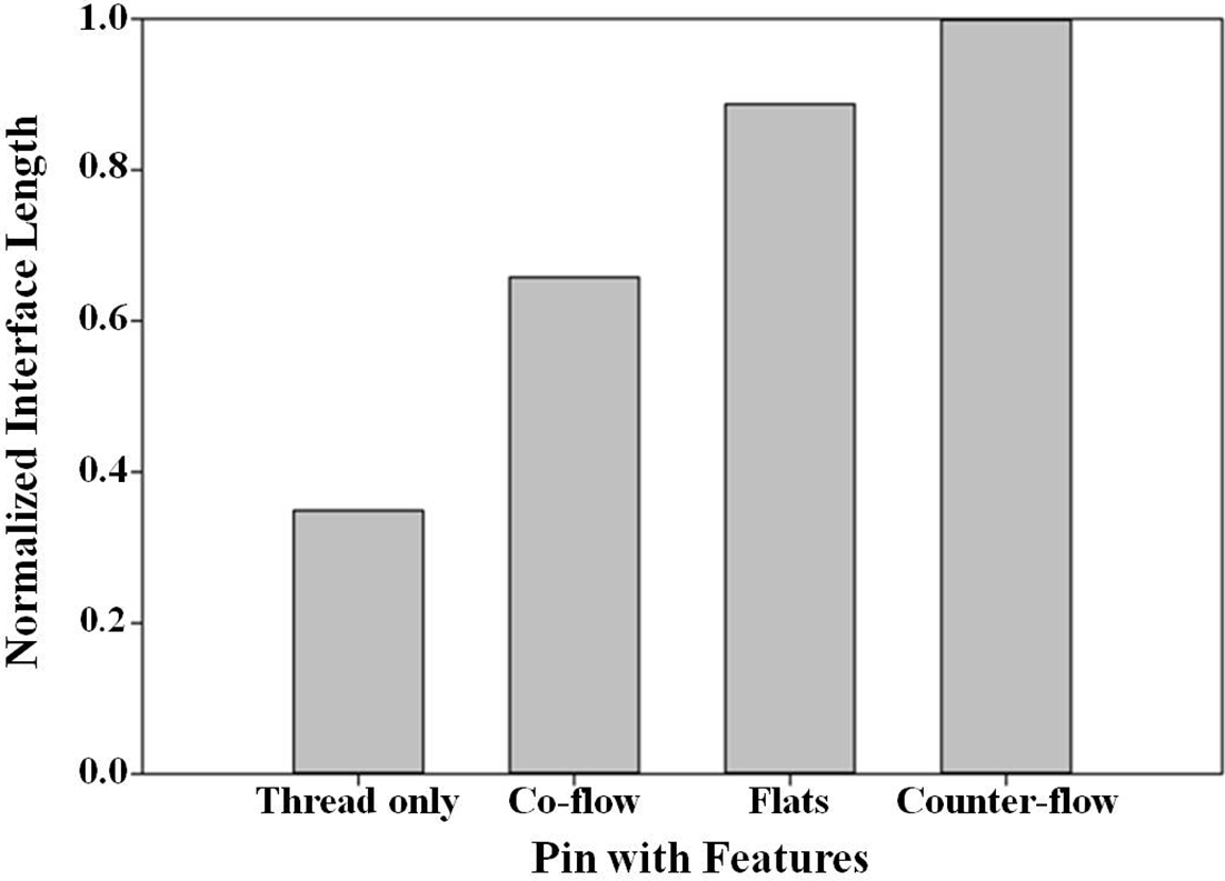
Normalised interface length between 6061 and 2050 depending on pin type
Based on the differences in weldability observed depending on the placement of the two alloys relative to the weld centreline, the material flow and high temperature deformation behavior must be somewhat different between AA2050 and AA6061 during FSW. Arbegast 22 developed a thermal and mechanistic flow model of FSW using thermomechanical simulator (Gleeble) data to establish constitutive relationships for flow stress and extrusion pressure for different aluminum alloys. In that work it was found that at relevant temperatures, extrusion pressure and flow stresses of AA6061 are lower than those of AA2195. Because the chemical compositions and properties of AA2195 and AA2050 are similar, the flow stress characteristics of these two alloys can be considered similar. The ideas set forth by Arbegast 22 were utilised to understand the flow behavior of these two alloys in bimaterial FSW. During welding, advancing side material AA6061 is required to flow around the retreating side and must displace AA2050 in order to make the trip. However, retreating side material, AA2050, requires higher extrusion pressure than 6061. The difference in required optimum extrusion pressure in bimaterial welds might inhibit mass balance in the nugget zone during material transportation. Consequently, flash and/or wormhole defects were evident in some of the welds with 6061 on the advancing side with higher reaction forces encountered by the pins (see next section). On the other hand, with AA2050 on the advancing side, extrusion pressure is initially high enough to extrude the 2050 material from the advancing side and move that material around the pin: it is possible for the high flow stress 2050 to displace the retreating side material (6061), which has relatively low flow stress and low required extrusion pressure. Therefore, mass balance in the nugget zone was satisfied and consequently effective material transportation with appropriate consolidation was achieved while 2050 was placed on the advancing side. Other studies have also found that defect free welds were more readily produced when stronger materials were placed on the advancing side during dissimilar material welds.8, 17–19
In plane reactions on pin
Figure 4 is a polar plot of average in plane reaction forces on the tools for different pin features with different alloy placements. The conventional direction of positive x axis force, positive y axis force and resultant force orientation with respect to tool rotational and travel direction during FSW are also presented schematically in Fig. 4. The force exerted by the work piece that impedes the forward motion of the tool is defined as the positive x axis force. The positive y axis force acts perpendicular to the x direction towards the advancing side from the retreating side. It is evident from Fig. 4 that the resultant in plane reaction forces are much lower when AA2050 is placed on the advancing side (enclosed in the blue circle) compared to having AA6061 on the advancing side (outside of the blue circle in polar plot). This is true in every case regardless of the quality of welds in terms of defect content. It can also be observed from Fig. 4 that, for some of the welds with 2050 on the advancing side, the y axis reaction force is very small compared to the x axis force. Interestingly, two welds have negative y force values as seen in the polar plot. The graph also shows that in almost all cases, the highest welding speed welds have the highest in plane resultant force.
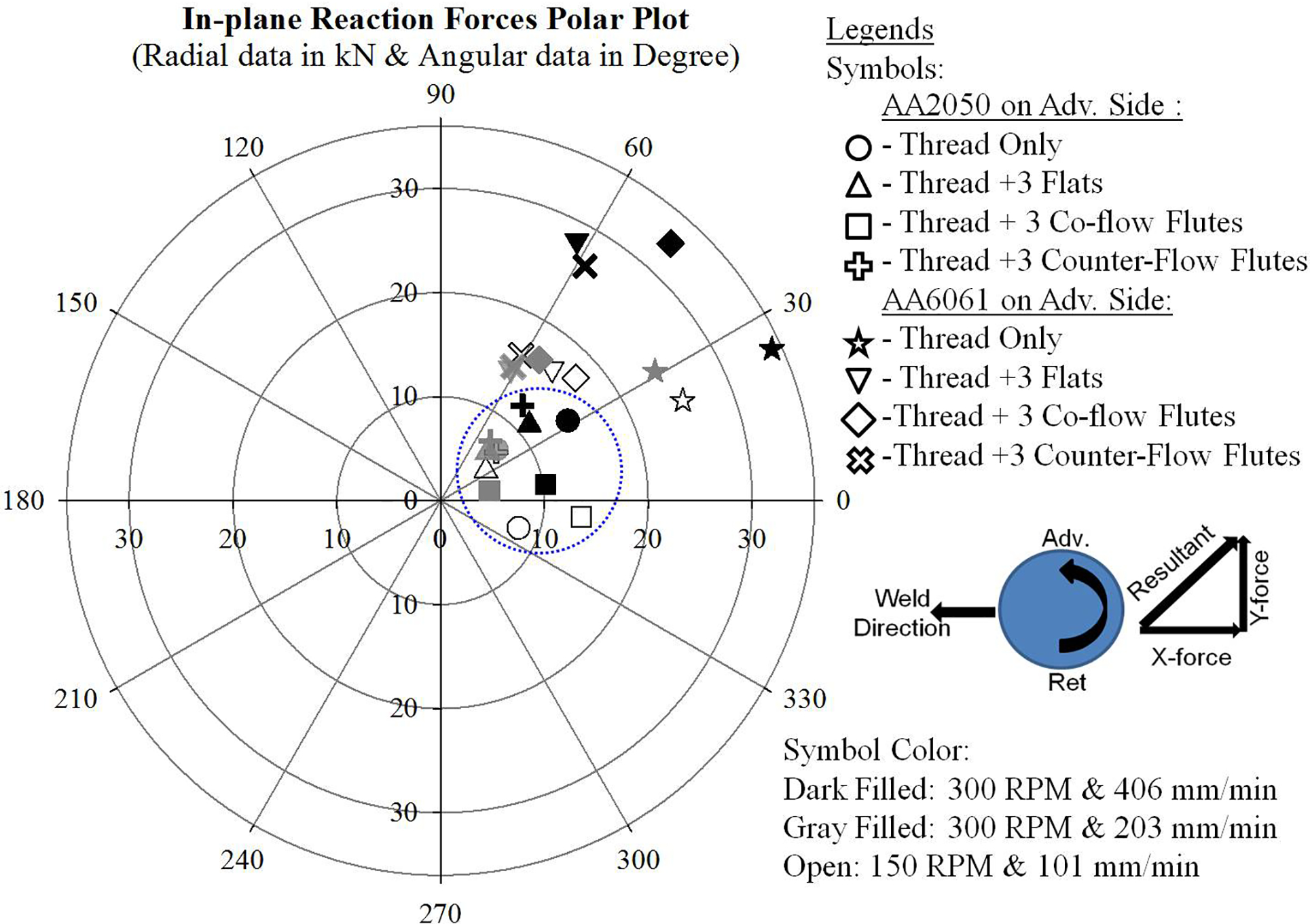
Average in plane reaction force in polar plot for different pin features, weld parameters and alloy placement with arrow marks showing conventional force coordinate system in FSW process
Forge force–torque–power–temperature relationships
Forge force in the z direction was adjusted for welding with different pin features to maintain a similar contact condition of the shoulder and the weld top surface. 23 The right hand threaded pins rotated in the counterclockwise direction tend to push material down and hence the tool up. However, additional features on pins will alter the upward thrust necessitating different levels of applied z force in order to maintain the desired shoulder contact. For welding with 2050 on the advancing side, the pin with thread+3 co-flow flutes required the highest forge force (z force) and the pin with thread+3 counter flow flutes required the lowest forge force to maintain similar plunge depth: this seems intuitively correct because it is anticipated that the counter flow flutes will reduce the upward thrust on the pin and the co-flow will increase it: the first by intensifying the downward material flow induced by the threads and the second by performing the opposite function. The threaded only pin and thread+3 flats required intermediate forge force when 2050 was placed on the advancing side. When welding with 6061 on the advancing side, threaded only pin and pin with thread+3 co-flow flutes required higher forge force than the pin with thread+3 flats and thread+3 counter flow flutes. It should be noted that the co-flow flute pin requires the highest forge force in every case except when large defects are observed in the threaded only pin welds (6061 on advancing side). Figure 5 is a plot of torque versus forge force for various tools, alloy arrangements and welding parameters. By examining the variation of required z force for a given parameter set, one can see the effect of tool features on required forge force (same color legend for same welding parameters) on the horizontal axis.
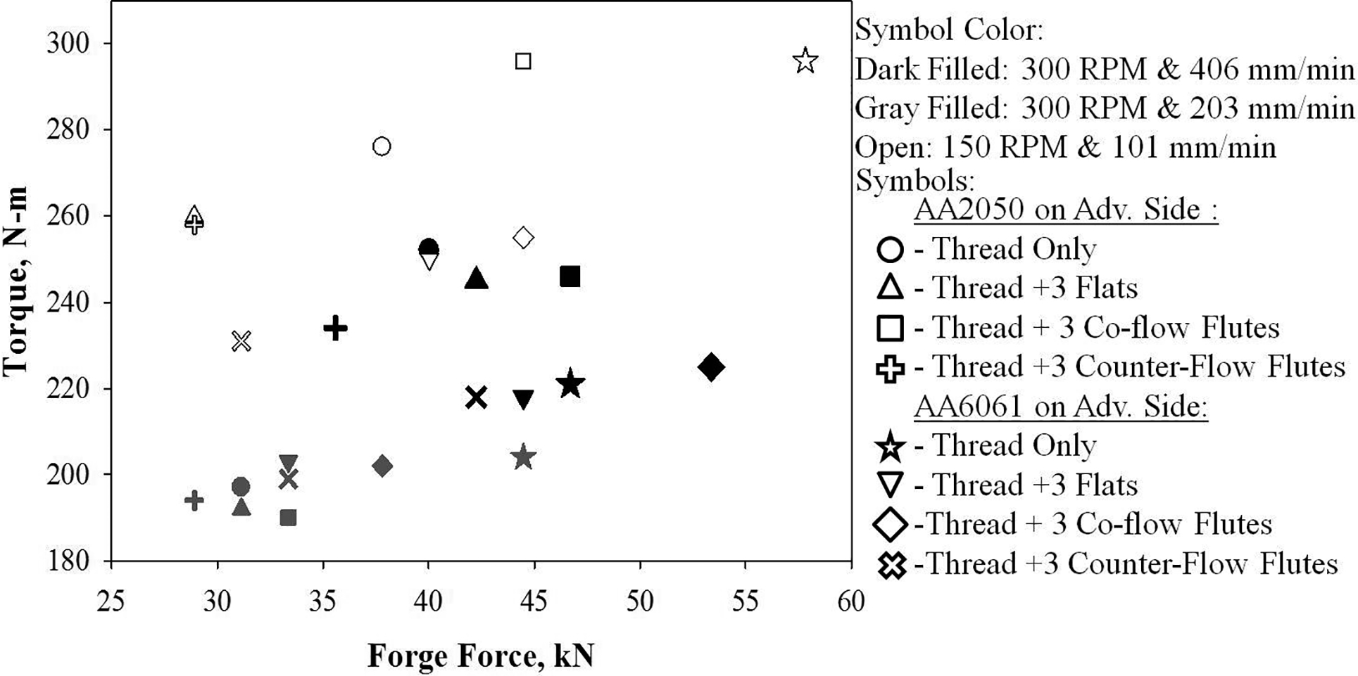
Torque as function of forge force for different tool and weld parameters
The torque versus forge force, graphed in Fig. 5, indicates that for all of the 300 rev min− 1 welds, at a given combination of alloy placement and welding speed, the torque is relatively insensitive to the applied forge force. It was observed in these welds that, regardless of alloy placement, variation of measured torque was insignificant (less than 5%), while considerable variations in forge forces (15–33% for different pins) were required. It may be that this is due to variation in the upward thrust due to pin features leading to an essentially constant pressure under the shoulder even though the z force is varied. With lower rotational (150 rev min− 1) and welding speed (101 mm min− 1) a greater change in torque with respect to forge force was observed for different pin features. For instance, in the defect free welds (with 2050 on advancing side and 150 rev min− 1), a forge force increase from 28·9 kN (pin with counter flow flutes) to 44·5 kN (pin with co-flow flutes), the required torque is increased from 258 to 296 N-m. While this torque increase is significant, it is still substantially less, percentage wise, than the increase in forge force (15 versus 54%).
The observation of higher torque at lower rev per minute (open symbols versus dark and gray filled symbols in Fig. 5) is consistent with generally observed trends and can be explained by the measured pin temperature as a function of weld power shown in Fig. 6. Higher rotational speed results in higher temperature and reduced torque, presumably due to the reduced flow stress of the material in contact with the tool. 24 The temperature increased significantly (increased by 55–80°C) when the weld parameters were changed from 150 rev min− 1 and 101 mm min− 1 to 300 rev min− 1 and 203 mm min− 1 (Fig. 5). However, at the same rotational speed, 300 rev min− 1, when welding speed is increased from 203 to 406 mm min− 1, the welding power increases, but temperature decreases, due to reduced heat input per unit volume of processed material.
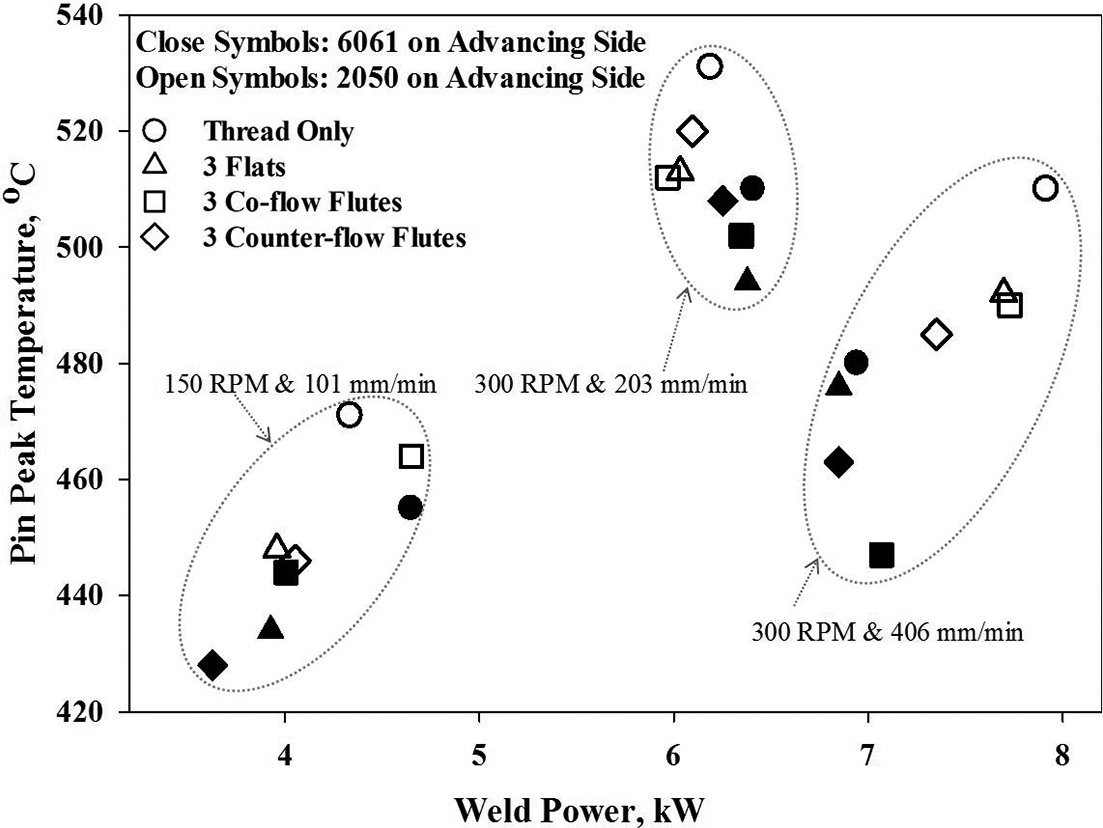
Pin peak temperature as function of weld power for different tools and weld parameters
Based on the data in Fig. 6, it can be generally seen that, all other things being equal, the welds made with 2050 on the advancing side have higher temperature than corresponding welds made with 6061 on the advancing side. This is true even when the measured weld power is lower for the 2050 advancing side welds (300 rev min− 1, 203 mm min− 1). It is not clear why this should be the case, however, it may be related to differences in amount of tool to specific alloy contact and the differing thermal conductivities of 6061 and 2050 (6061 is higher). From Fig. 6, it can also be seen that for every combination of alloy placement and welding parameters, the highest pin temperature is measured in the thread only pin. In several, but not all cases, the power required when welding with the thread only pin is greater, and this can certainly explain the higher temperature. However, it is more interesting to consider why might the power be generally higher with the threaded only pin? Higher power consumption for production of defect free welds implies a less efficient tool design. Examination of the cross-sections in Fig. 1 indicates a quite significant difference in the level of mixing between pins with and without thread interruptions as does the data in Fig. 3. The differences in intermixing obviously result from some fundamental differences in the flow patterns due to the different tools. It seems likely that the thread interruptions, and in particular, those which are not complimentary to the flow produced by the threads, may act as cutting edges and promote the movement of materials around the tool as rigid body motions rather than solely as a shear flow. The typical shear zone model of FSW material flow in other studies25, 26 also imply that all of the material making up the weld goes through a severe shearing process (with greater strain on the advancing than retreating side) and that the maximum temperature in the deforming material will be at the tool surface. However, if some of the material transport occurs via rigid body motion, then some regions of high deformation could be remote from the tool surface, leading to reduced tool temperature and, possibly, lower total deformation required to maintain the material balance between the leading and trailing sides of the tool.
Conclusions
In this research, the effect of alloy placement and pin features (thread/flats/flutes) along with changing the process control parameters were examined in dissimilar material FSW of AA2050 and AA6061. The following concluding remarks are drawn based on observed trends.
Alloy placement has a significant effect on weldability of bimaterial FSW. Placing stronger material, i.e. AA2050 on advancing side resulted in reduced defect content.
In plane reaction forces on the tool were reduced for welding with 2050 on the advancing side.
The presence or absence of thread interruptions had significant effects on weldability and material flow.
Thread resulted in large macroscopic defects in all cases where 6061 was on the advancing side.
Flats produced defect free welds in all but one case (at the highest welding speed, 6061 on the advancing side).
Counter flow flutes tended to produce near root defects: this is intuitively reasonable as the counter flow flutes would tend to move material away from the root.
Co-flow flutes produced surface breaking defects in some cases: this is intuitively reasonable as the co-flow flutes will tend to move more material away from the crown than will the threads alone.
Thread interruptions, especially those which did not reinforce the pin flow, resulted in substantially greater intermixing of the two alloys: it is suggested that this is due to increased levels of material transport via rigid body motion.
Thread interruptions that are neutral (flats) or oppose the thread flow (counter flow flutes) reduce the needed forge force relative to the thread only or thread+co-flow flutes: this is intuitively reasonable and is compatible with conclusions 3-d and 3-e.
The temperature was uniformly higher for welds made using the threaded only tool: it is supposed that this is related to conclusion 3-e.
It is important to note that while some of these conclusions may be quite general, subtle variations in tool geometry might create substantial changes. In addition, different weld parameter ranges and selected alloys could lead to different conclusions. Regardless, the results presented here tend to be self consistent, and it seems reasonable to expect that they can be used to guide process development and tool selection in similar cases.
Acknowledgements
The authors acknowledge the financial support of the Center for Friction Stir Processing, which is a National Science Foundation I/UCRC supported by grant no. EEC-0437341. The authors thank Mr D. Wilhelm, Department of Mechanical Engineering, University of South Carolina, Columbia, SC, USA, for his help in manufacturing pins and preparing the weld joints.