
Abstract
A prominent benefit of friction stir welding process is to join plates with dissimilar material. In this study, an attempt is made to find effects of tool offset, plunge depth, welding traverse speed and tool rotational speed on tensile strength, microhardness and material flow in dissimilar friction stir welding of AA1100 aluminium alloy and A441 AISI steel plates. Here, one factor at a time experimental design was utilised for conducting the experiments. Results indicated the strongest joint obtained at 1·3 mm tool offset and 0·2 mm plunge depth when the tool rotational speed and linear speed were 800 rev min− 1 and 63 mm min− 1 respectively. The maximum tensile strength of welded joints with mentioned optimal parameters was 90% aluminium base metal. Fracture locations in tensile test at all samples were in aluminium sides. Owing to the formation of intermetallic compounds at high tool rotational speed, the microhardness of joint interface goes beyond that of A441 AISI steel.
Introduction
Compared to the other welding processes, friction stir welding (FSW) is a solid state joining that enables to join dissimilar matetrials. In this process, a non-consumable rotational tool penetrates the joint line and makes the surrounding material soft by generation of frictional heat. After penetration, welding tool starts moving forward and pulls plastic materials from the front to the rear side with forging force and combined them. 1
In joining of aluminiums and steels by fusion welding methods, due to high heat input into the faying surfaces, thick brittle and hard compound layer is formed. This compound can damge the mechnical properties of the joints.2, 3 Therfore, in recent years, the researchers focused on joining of such materials by the FSW process. They extensively used FSW for butt joining of aluminiums to steels and studied mehanical properties, microstructures and material flow. For instance, Jiang and Kovacevic 4 succeeded to join 6061 aluminium alloy to AISI 1018 steel by the FSW process. The joint had desirable mechanical strength, and they showed that by increasing tool rotational speed, deffect free joints are produced. Tanaka et al. 5 studied post-weld properties of dissimilar friction stir welds of mild steel to AA7075-T6 aluminium alloy. They reported that the joint strength increased with reduction in thickness of the FeAl3 intermetallic compound at the weld interface. Morover, they indicated that the joint strength was ∼40% lower than that of the base aluminium alloy. Lee et al. 6 investigated interfacial reaction in dissimilar FSW of 304 stainless steel to AA6056-T4 aluminium with thickness of 4 mm. They reported that the reaction layers of joints consisted of mixed layers of elongated and ultrafine grains and the Al4Fe intermetallic compound layer. Ghosh et al. 7 studied dissimilar FSW of commercially pure Al to 304 stainless steel. They found that diffusion of Fe, Cr and Ni was substantial within Al; however, diffusion of Al within steel is limited. In addition, they reported that structural changes mainly took place within the aluminium side. Uzun et al. 8 investigated the properties of friction stir welded AA6013-T4 aluminium alloy to X5CrNi18-10 stainless steel. They reported that fatigue properties of AA6013-T4/X5CrNi18-10 stainless steel joints were ∼30% lower than those of the AA6013-T6 alloy base metal. Watanabe et al. 9 conducted experiments on the effects of an FSW tool offset and tool rotational speed on the tensile strength and the microstructure of the SS400 mild steel and AA5083 aluminium alloy. They found that the maximum tensile strength of the joint was ∼86% of that of the aluminium alloy base metal when 90% of the cross-sectional area of pin was placed in the aluminium side. Chen 10 performed a parametric study on FSW of AA6061-T651 aluminium alloy to low carbon steel. He indicated that lower rotational and linear speed can result in higher impact values of weld strength. Dehghani et al. 11 investigated the effects of FSW parameters on mechanical properties of AA3003-H18 aluminium alloy to mild steel. They reported that the joint strength >90% of aluminium base metal was reachable by controlling heat input. The thickness of intermetallic layer increased from 0·8 to 7·8 μm by increasing the heat input. Liu et al. 12 attemped to join AA6061-T6 aluminium alloy and TRIP steel. They reported that welding speed had an insignificant effect on mechanical welding force, temperature distribution, strain rate and intermetallic layer composition. On the other hand, higher rotational speed can elevate the temperature distribution and vertical and lateral force and can also influence the composition of the formed intermetallic compound layer.
Although there are numerous works that join the various aluminium alloys to steels by the FSW process, joining of AA1100 aluminium to A441 AISI steel has not been reported so far. In the present study, an extensive experimental approach is made to find effects of FSW parmeters like tool offset, plunge depth, tool tilt angle, traverse speed and tool rotational speed on tensile strength, microhardness and material flow of welded samples. Then, the optimal parameter setting for each quality characteristic is presented and completely discussed.
Experimental
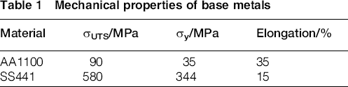
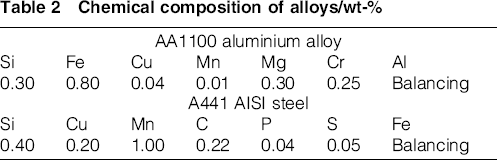
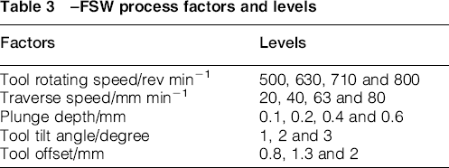
In this research, AA1100 aluminium alloy and A441 AISI plates with 3 mm thickness were cut into dimensions measuring 150 mm long and 50 mm wide by a universal sawing machine. The mechanical properties and chemical composition of base metals are presented in Tables 1 and 2. A flexible clamping system made of high carbon steel was designed to clamp the plates in their proper positions. Single pass friction stir butt welds were conducted using a milling machine, in position control, and FSW tool was made of tungsten carbide. Figure 1 displays the tool used in this study. The tool has a 20 mm diameter shoulder with a conical cavity and a conical probe measuring 4–6 mm in diameter and 3·4 mm in length. In these experiments, steel plates were located on advancing side. The experimental set-up including milling machine and its clamping system is shown in Fig. 2. For conducting the experiments, a single factor experimental design was used. It means that for finding effect of a given parameter, it varies through the levels, while the others are kept constant. Table 3 presents the process factors and their corresponding levels.
Mechanical properties of base metals
Chemical composition of alloys/wt-%
Schematic view of tool specifications
Milling machine and its clamping system used in FSW experiments
–FSW process factors and levels
To study the weld behaviour in tensile test, three tensile tests in transversal direction along the weld line were wire cut from each joint. The tensile test specimens were prepared according to ASTM: E8M-13 13 and tested using a crosshead speed of 1 mm min− 1. The dimensions of tensile specimen and images of the tensile specimens before the tensile test are shown in Fig. 3. The Vickers microhardness was also measured using Shimadzu Vickers indenter on cross-section of welded samples with a test load of 50 gf for 15 s. The specimens for metallographic examination were sectioned to the required sizes from the joint comprising stir zone and then grinded using different grades of emery papers. Final polishing was done using the diamond compound in the disc polishing machine. The polished samples were etched using 10% NaOH to show general flow structure of the alloy. Macro- and microstructural analysis have been carried out using a light optical microscope (VERSAMET-3) incorporated with an image analysing software (Clemex-Vision). In addition, for finding formation of intermetallic compound in the weld region, X-ray diffraction (XRD) technique and scanning electron microscopy (SEM) analysis were used. In addition, the temperature changes during FSW were experimentally recorded using K type thermocouple inserted in the weld centreline.
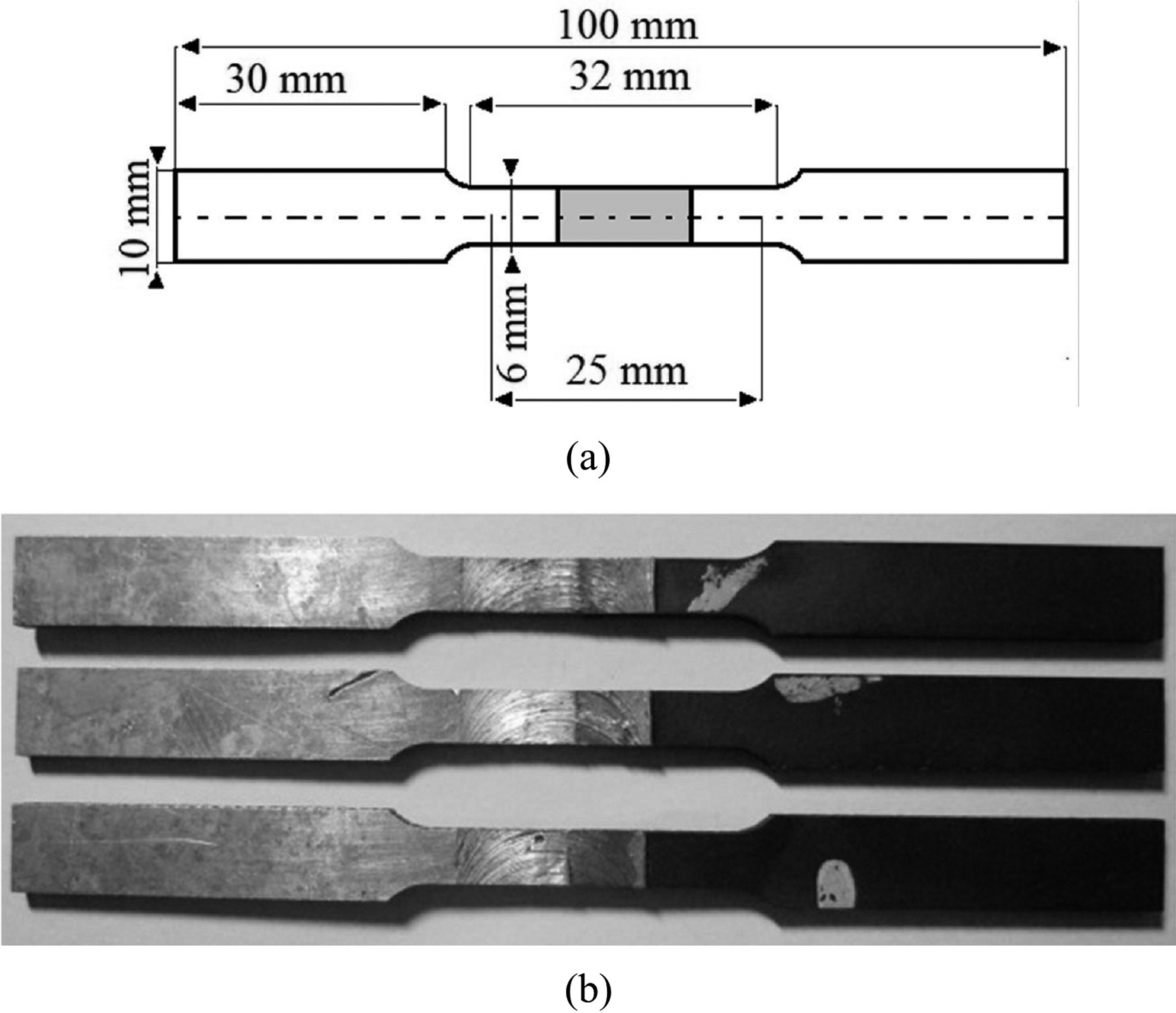
a dimensions of tensile specimen; b tensile specimens before testing
Results and discussion
Effects of tool offset
In order to find the effect of tool offset on material flow and mechanical properties, the experiments were performed with 0·8, 1·3 and 2 mm tool offsets in the aluminium side. Figure 4 shows the effect of tool offset on welding surface quality and material mixing of joints, which were fabricated at aforementioned offset values, while other welding parameters such as tool rotary speed, traverse speed, tilt angle and plunge depth were kept constant at 800 rev min− 1, 63 mm min− 1, tool tilt angle 2° and plunge depth 0·2 mm respectively. Figure 4a demonstrates weld surface quality at 0·8 mm tool offset. Shallow tunnels and poor material mixing are observed in weld line. When the tool offset is low, the deformation resistance of steel causes producing inadequate material mixing and damages surface quality of the weld. In the 1·3 mm tool offset, the width of the deformed zone in aluminium side becomes more and this phenomenon causes acceptable flow on the weld line between the two metals (see Fig. 4b). This is due to lower sliding fraction and lower torque that causes better material flow.14, 15 At high tool offset (i.e. 2 mm), the tool axis is far from the base metal interface; therefore, poor material mixing occurs at the weld line due to less stir action (see Fig. 4c).
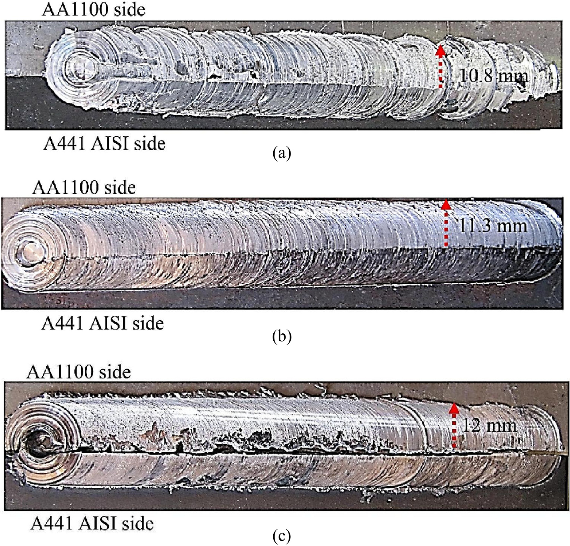
Effects of tool offset on surface quality of welded samples by 800 rev min− 1, 63 mm min− 1, tool tilt angle 2°, plunge depth 0.2 mm and a 0.8 mm, b 1.3 mm and c 2 mm offset
The effects of tool offset on the joints efficacy, i.e. a ratio of joint strength to aluminium base strength, are shown in Fig. 5. It is inferred from this figure that the joints with high efficiency are obtained when the tool offset is equal to 1·3 mm. In 0·8 mm tool offset, due to poor material mixing (as discussed above), the defects occurred in the weld line and causes reduction of the joint's strength. The improper mechanical strength of weld line due to low tool offset can be compensated by increasing tool rotational speed to some extent. In the offset of 1·3 mm, the sliding friction and the exerted torque decrease, which will make more stir. The generated heat in aluminium side trnasferred into the steel and causes more plastic deformation in the A441 AISI side. Therefore, the joint eficiency increases dramatically at the 1·3 mm tool offset. On the other hand, at 2 mm tool offset, the pin axis is far from the interface and tool stirs lower materials of steel. Therfore, the material mixing is low and joint efficiency is low.
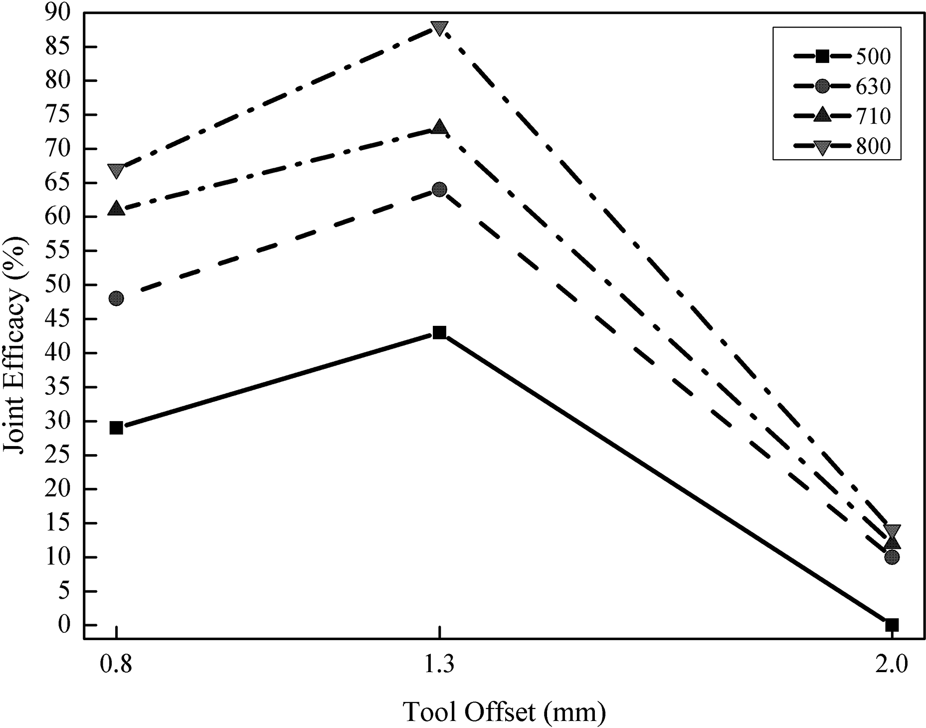
Effects of tool offset on joint efficacy (welded samples by 800 rev min− 1, 63 mm min− 1, tool tilt angle 2° and plunge depth 0.2 mm)
Effects of tool plunge depth
Tool plunge depth plays a predominant role in determining FSW process characteristics. It has direct impacts on heat generation and amount of friction between the tool and workpieces. Tool plunging refers to welding axial force and welding pressure, which cause changes in total heat generation during the welding process. 16
By an increase in tool plunge depth, the friction between the tool and the workpieces becomes more and causes higher amount of heat in tool/workpiece interface. In the present study, the plunge depth varies over 0·1, 0·2, 0·4 and 0·6 mm, while the other factors are kept constant (i.e. 1·3 mm tool offset, tool tilt angle 2°, 710 rev min− 1 tool rotational speed and 40 mm min− 1 traverse speed). Figure 6 shows the macrostructure of the cross-sections of the joints with different tool plunge depth. In 0·1 mm tool plunge depth, the upper zone of plates welded together (Fig. 6a). The low plunge depth causes poor material mixing, incomplete superficial flow and emergence of crevice inside the joint. The formation of these defects decreases the ultimate tensile strength and joint efficacy. Interaction between base metals occurred at the upper area of joint, which inferred that the shoulder rotation was the main factor of material mixing and downward forging (axial force) was not adequate. Hence, the boundary gap was formed between two sheets. With increasing axial force in 0·2 mm plunge depth, material flow and interlace became more, and according to Fig. 6b, mixing of materials increases. The effects of this phenomenon cause A441 AISI to push downward and AA1100 was stirred inward of the steel.
Macrostructure of welded samples by 710 rev min− 1, 40 mm min− 1, tool tilt angle 2°, 1.3 mm tool offset and a 0.1 mm, b 0.2 mm, c 0.3 mm and d 0.4 mm tool plunge depth
By increasing tool plunge depth up to 0·4 mm, axial force and thereby downward forging force increase; correspondingly, it will increase stir zone squeezing. Therefore, hot metal sticks on the shoulder surface as shown in Fig. 6c. As a result of the higher force in this plunge depth, plasticised materials were driven toward out of stir zone. Over necessitous axial force in 0·4 mm plunge depth causes the dislodge materials from the joint zone and makes many defects in stir zone. When the plunge depth is equal to 0·6 mm, due to excessive axial force, frictional heat increased material flow under tool shoulder becomes easier. Large chunks of steel and aluminium are visible in the cross-section of the joint, representing the excessive downward forging force and sticking of materials (Fig. 6d). This excessive force led to the formation of unsound joint and produced narrow crack and tiny holes.
Fig. 7 shows the joint efficiency of welded samples at different plunge depths. It can be inferred from the figure that the joint efficiency increases by increasing the plunge depth and reaches a maximum value at 0·2 mm. Then, by further increasing the values of plunge depth (i.e. 0·4 and 0·6 mm), the joint efficiency decreases correspondingly. When the plunge depth is relatively low (i.e. 0·1 mm), the joint efficiency reaches 60% aluminium base metal. At 0·2 mm plunge depth, the joint efficiency is ∼80% aluminium base metal strength. Owing to appropriate flow and proper stirring action, the fracture location is in the aluminium side. The joints that were fabricated in 0·4 and 0·6 mm plunge depths had 53 and 48% aluminium base metal strength respectively. Owing to high axial force and propulsion of the material from the stir zone, material mixing is not as well in 0·2 mm tool plunge depth. On this basis in tension test, the fracture location is in the stir zone.
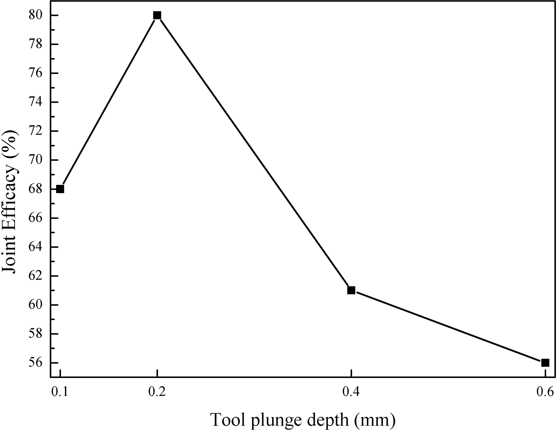
Effects of tool plunge depth on joint efficacy (welded samples by 710 rev min− 1, 40 mm min− 1, tool tilt angle 2° and 1.3 mm tool offset)
Effects of tool tilt angle
The tool tilt angle is a factor that has great impact on FSW process characteristics. This parameter directly affects the flow of the plasticised material around shoulder. 17 By an increase in tool tilt angle, downward forging force and heat generation rate increase subsequently. In order to analyse the effects of tool tilt angle, it is varied over 1°, 2° and 3°, while the other parameters are kept constant (tool rotational speed of 800 rev min− 1, 80 mm min− 1 traverse speed, 0·2 mm plunge depth and tool offset of 1·3 mm). Figure 8 presents the flow of plasticised material under various tool tilt angles. From Fig. 8a, it is observed that the joints that were fabricated at 1° tilt angle have a bulbous shape with widely spaced stripes. When the tilt angle is relatively low (i.e. 1°), due to insufficient axial force, the stirred material is less and it causes formation of irregular material flow. At 2° tool tilt angle (Fig. 8b), the surface flow is improved and the distance between the formed rings becomes less. Higher forging force provides better material flow and improves the surface quality of the welded region. At tilt angle of 3°, although the forging force increases, vacant space in the back side of the tool increases, and during the process, the material flow becomes irregular and non-uniform. Therefore, some dents, wrinkles and surface voids are observed in the welding region (Fig. 8c). Figure 9 shows the effects of tool tilt angle on joint efficiency. From this figure, it is seen that the joint efficiency increases with an increase in tool tilt angle and reaches a maximum value at 2° tilt angle, and then by further increase in tilt angle, the joint efficiency decreases subsequently.
Surface material flow in a 1°, b 2° and c 3° tool tilt angle (tool rotational speed of 800 rev min− 1, 80 mm min− 1 traverse speed, 0.2 mm plunge depth and tool offset of 1.3 mm)
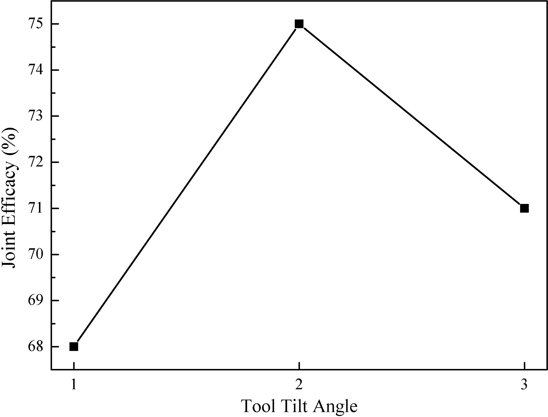
Effects of tool tilt angle on joint efficacy (tool rotational speed of 800 rev min− 1, 80 mm min− 1 traverse speed, 0.2 mm plunge depth and tool offset of 1.3 mm)
Effects of tool rotational and traverse speeds
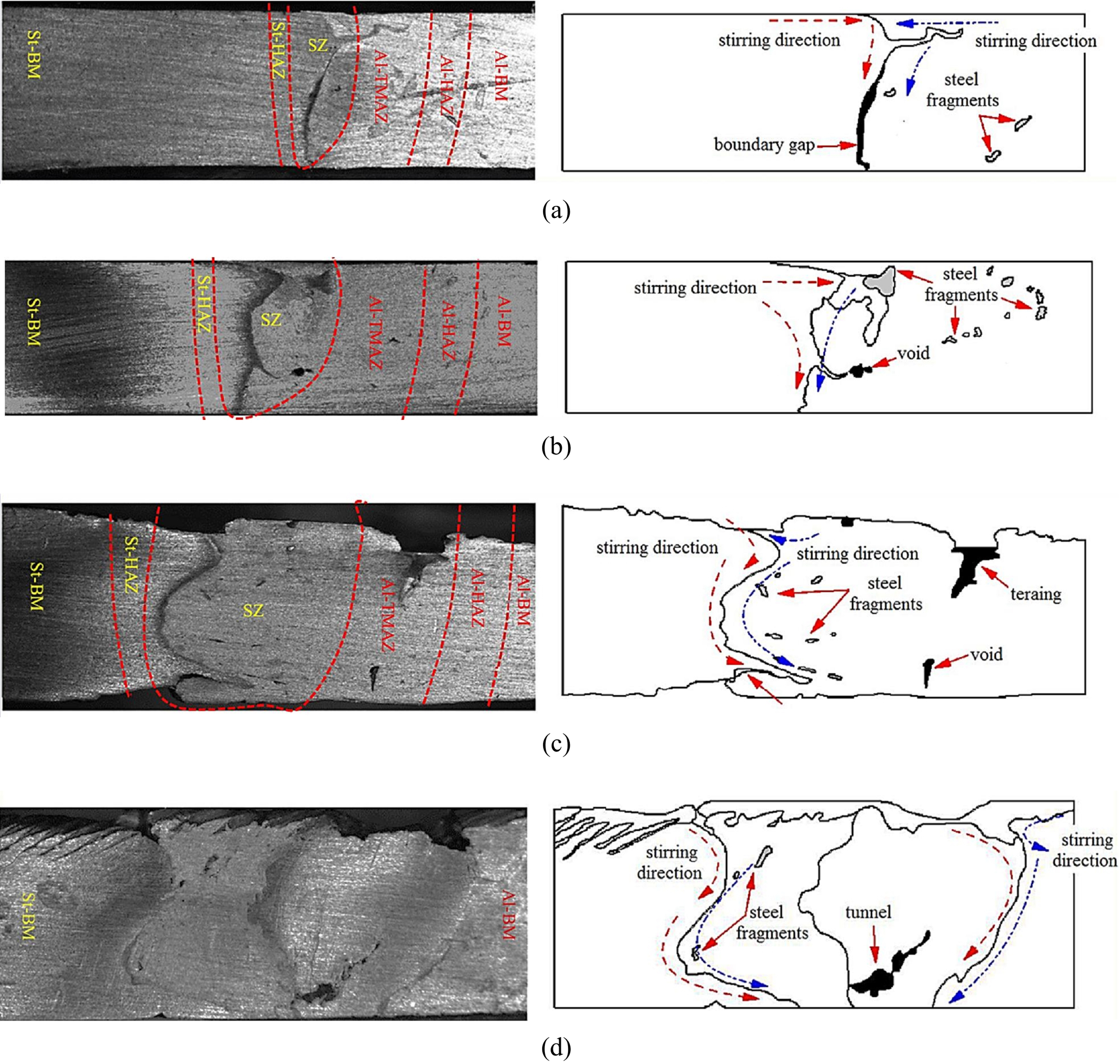
Based on previous research, researchers have reached a consensus that the tool rotational (ω) and traverse (V) speeds are the most thermogenesis factors during FSW. 17 Accordingly, the effects of tool rotation and travelling seeds were investigated on the heat generation and stir zone defects. Based on the selected parameters in this study, the proportion of the generated heat on the AA1100 melting temperature is shown in Fig. 10. According to this figure, it is inferred that by increasing rotational speed of the tool, the heat input increases. Increasing the rotational speed of the tool leads to more material flow, plastic deformation and the subsequent increasing of heat generation. Another noteworthy point in Fig. 10 is that with increasing linear speed, heat generation in stir zone is reduced. The reason for this phenomenon is that faster linear speed reduces the durability of heat source in stir zone. 17 According to the figure, it is seen that the higher value of temperature is obtained at higher tool rotation speed (i.e. 800 rev min− 1) and low welding speed (i.e. 25 mm min− 1). Therefore, at this condition, more heat transfers to the welding line. Hence, under such situation, the plasticisation and stirring action improve and cause better material flow. Figure 11 presents the macrostructure of the joints fabricated at various tool rotation speeds at 63 mm min− 1 traverse speed, 2° tilt angle, 0·2 mm plunge depth and 1·3 mm tool offset. It is seen from the figure that at 500 rev min− 1 (Fig. 11a), due to low heat generation and improper heat flux, the long worm hole is formed in the aluminium side. By increasing the tool rotational speed, due to higher frictional heat, the defects disappeared (see Fig. 11b). At 710 rev min− 1 (Fig. 11c), due to further heat and stir action of the tool shoulder, the steel base metal is stretched into aluminium and steel fragments separated in the aluminium bed. However, this amount of heat is not enough to affect wider area of steel side. For this reason, only a thin layer of steel was affected by plastic deformation. As shown in Fig. 11d, mechanical mixing of materials increases joint made by tool rotation speed of 800 rev min− 1. This may be attributed to higher heat input and better material plasticisation.
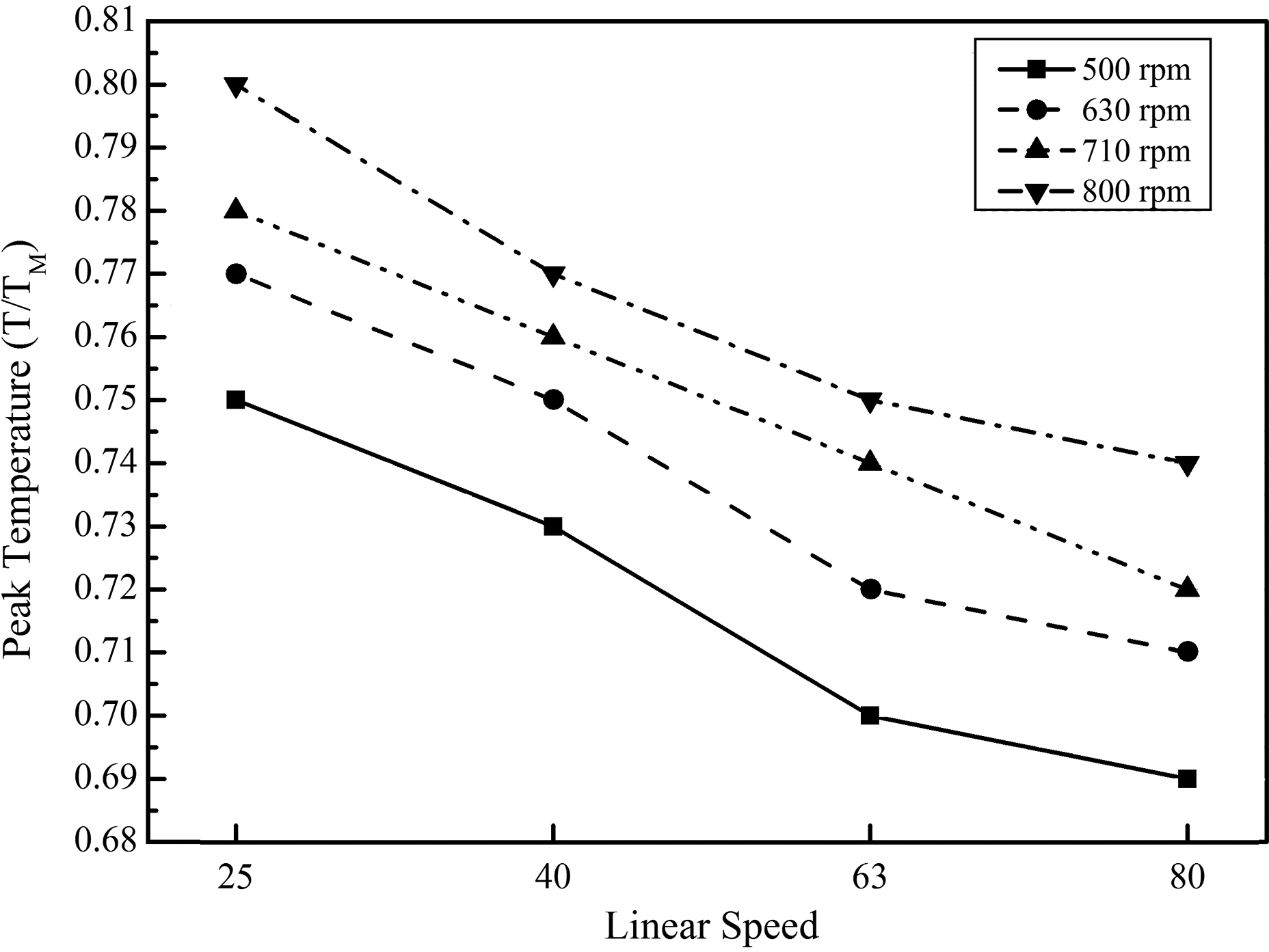
Effects of tool rotational and traverse speed on peak temperature (0.2 mm plunge depth, tool offset of 1.3 mm and 2° tilt angle)
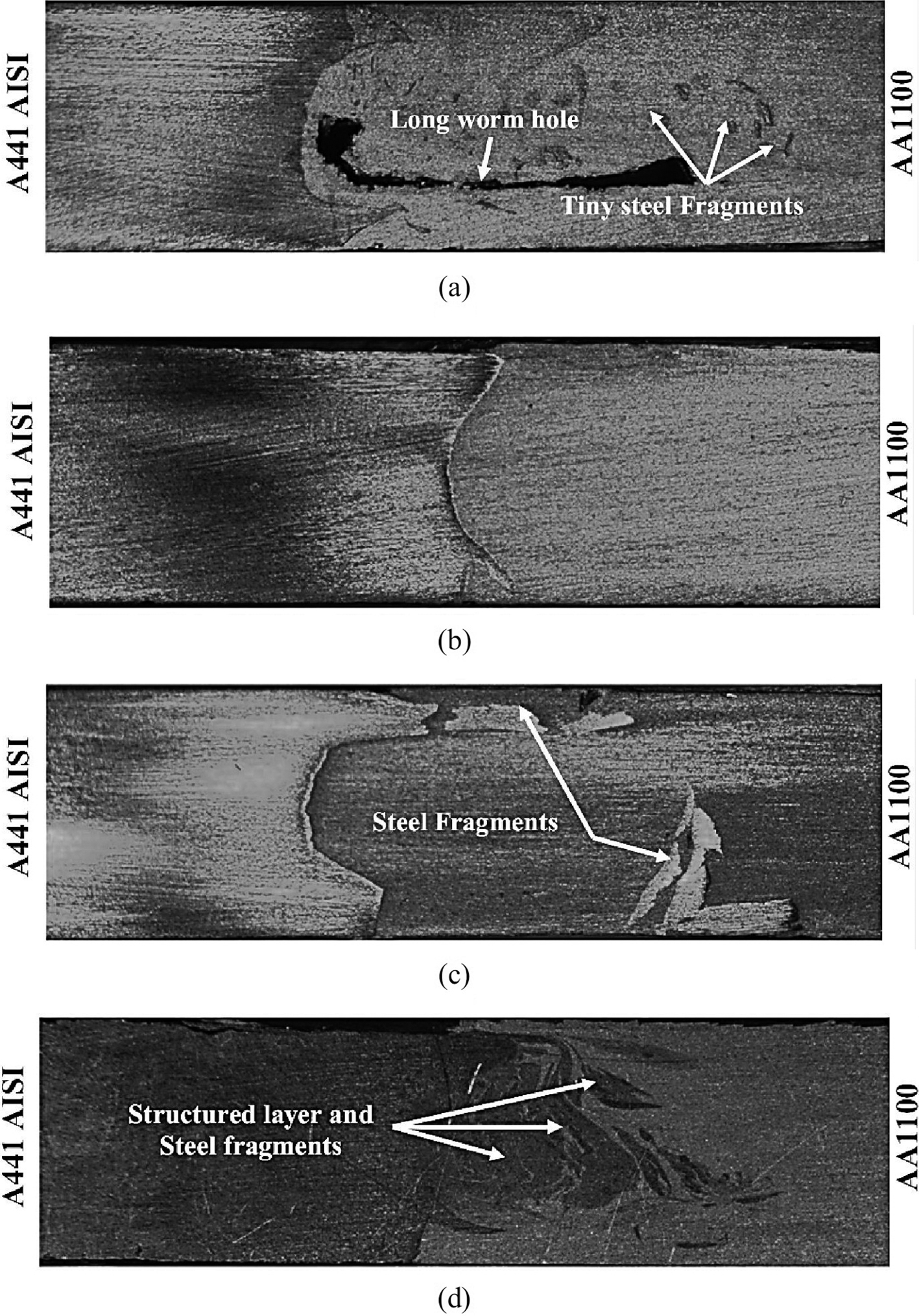
Effects of heat input on macrostructure of welded samples by a 500rev min− 1, b 630 rev min− 1, c 710 rev min− 1 and d 800 rev min− 1 (63 mm min− 1 travelling speed, 0.2 mm plunge depth, tool offset of 1.3 mm and 2° tilt angle)
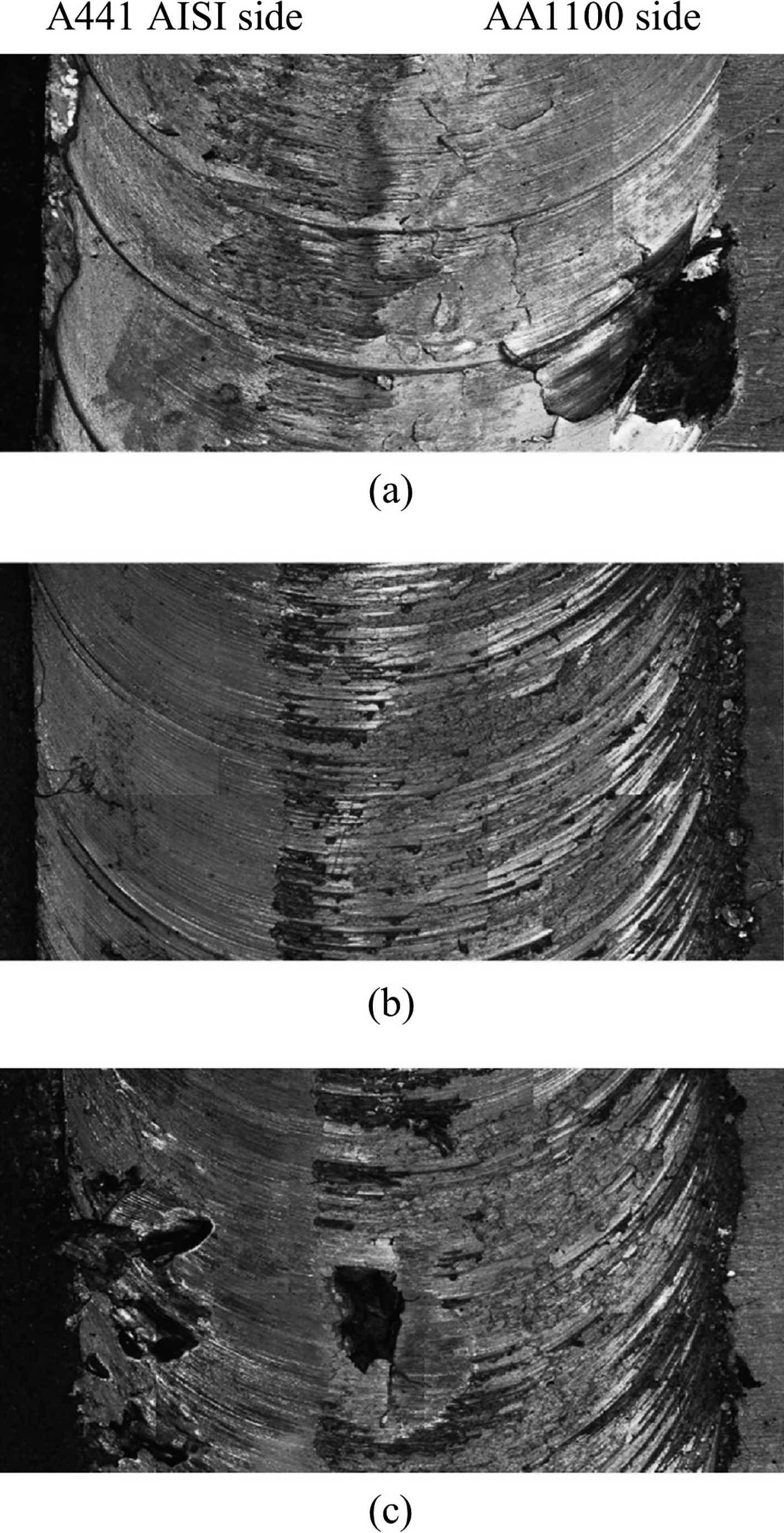
Fig. 12 shows the surface material flow of joint under various traverse speeds at 800 rev min− 1, 2o tilt angle, 0·2 mm plunge depth and 1·3 mm tool offset. It is seen from this figure that by increasing the traverse speed, the surface flow quality is increased. The most important factors in these changes are entrance of more material in stir zone and more strain rate that occurs with increasing traverse speed.18, 19 The formation of surface defects in joints that are welded by 25 mm min− 1 traverse speed is the result of the unsuitable forging force and non-uniform interned material in the stir zone, as shown in Fig. 12a. Material mixing pattern in 40 mm min− 1 traverse speed is seen in Fig. 12b. When traverse speed increases from 25 to 40 mm min− 1, the cooling rate increases. Similar to 25 mm min− 1, heat source slow footed forward moves in 40 mm min− 1 welding speed, leading to a decrease in the cooling rate progress. Thermal properties and contraction inconsistency between AA1100 and A441 AISI cause aluminium dragged steel to base metal environ sides during cooling. This phenomenon made shallow gap in joint. With increasing heat abate, steel resists against aluminium pressure; hence, tiny voids and surface interstice are formed on the welded area. At higher welding speed, the cooling rate and stir zone strain rate increase, and entrance material and cooling rate got better condition compared to the previous situation. Mentioned parameters improved surface gloss and removed defects that are visible in Fig. 12c and d.

Surface material flow at different traverse speed: a 25 mm min− 1; b 40 mm min− 1; c 63 mm min− 1; d 80 mm min− 1 (800 rev min− 1, 2° tilt angle, 0.2 mm plunge depth and 1.3 mm tool offset)
Tensile strength
Fig. 13 shows tensile properties of the joints at various rotational and traverse speeds under constant plunge depth 0·2 mm, tool tilt angle 2° and 1·3 mm tool offset. It is inferred from this figure that by increasing tool rotational speed, the tensile strengths of the joints increase consequently. On the other hand, it is seen that the joints with high traverse speed have higher tensile strength due to better material mixing and elimination of surface voids, which are produced at low cooling rates. The maximum strength of the welded joints is 90% aluminium base metal, and minimum strength is 30%. The strength of the joints that are welded at 500 rev min− 1 is lower than the others. This low strength may be attributed to the formation of worm and tunnel defects that are formed in the lower zone of the weld window. With increasing rotational speed, welding heat input increases and improves material plasticisation and stir action. Hence, under such condition, structured layers are formed and tensile strength increases. As it is seen in Fig. 14, the highest strength is related to the joint that is fabricated by 800 rev min− 1 tool rotary speed and 63 mm min− 1 welding traverse speed with 80 MPa strength. The weakest strength is 40 MPa and belongs to the joint that was welded by 500 rev min− 1 and 25 mm min− 1.
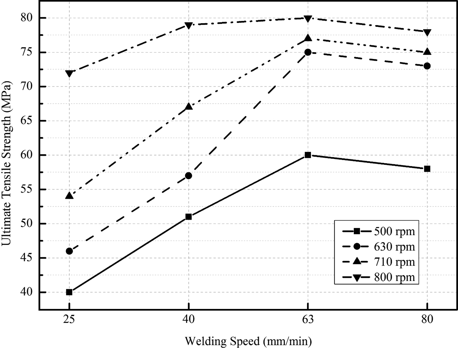
Mechanical properties of FS welded samples at various rotational and traverse speeds and constant plunge depth 0.2 mm, tool tilt angle 2° and 1.3 mm tool offset
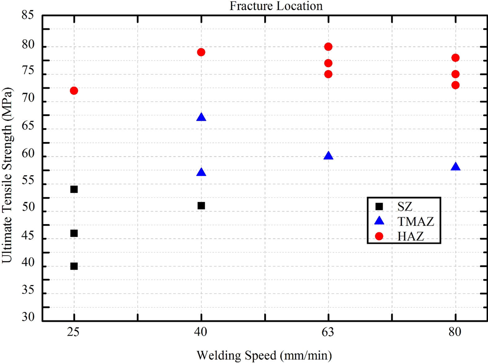
Fracture of FS welded samples at various rotational and traverse speeds and constant plunge depth 0.2 mm, tool tilt angle 2° and 1.3 mm tool offset
The fracture location in tensile test is a good witness to justify claims in analysing tensile properties. In these tests, fractures occurred in the stir zone, thermomechanical affected zone and heat affected zone (HAZ) at various sides of welded samples. Figure 15 demonstrates the fracture locations of various welded samples. From this figure, it is observed that in joints that have tensile strength < 55 MPa, their fraction locations are in the stir zone. Specimens that were welded under 500 rev min− 1 and 25 mm min− 1, 500 rev min− 1 and 40 mm min− 1, 630 rev min− 1 and 25 mm min− 1, and 710 rev min− 1 and 25 mm min− 1 have this feature. By increasing the traverse speed, the fracture location shifts from the stir zone to the thermomechanical affected zone. Joints that were fabricated by 500 rev min− 1 and 63 mm min− 1, 500 rev min− 1 and 80 mm min− 1, 630 rev min− 1 and 80 mm min− 1, and 710 rev min− 1 and 40 mm min− 1 were broken from the thermomechanical affected zone. Increase in both tool rotational speed and traverse speed above 710 rev min− 1 and 40 mm min− 1 causes good structure, and this issue is the reason of some welds that were broken from HAZ. All joints were welded together with 800 rev min− 1 rotational speed, and the joints that were fabricated by 630 rev min− 1 and 63mm min− 1, 630 rev min− 1 and 80 mm min− 1, 710 rev min− 1 and 63 mm min− 1, and 710 rev min− 1 and 80 mm min− 1 were broken from the HAZ region. Considering the observed cases, it can be concluded that the location of failure in tensile test depends on the joint microstructure and the defects.
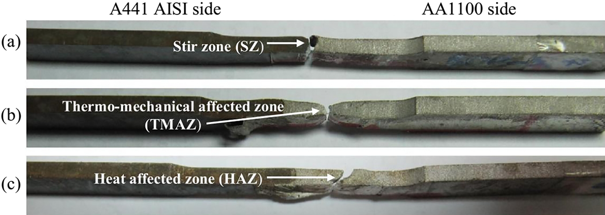
Fracture locations in specimens that were welded at 710 rev min− 1 and a 25 mm min− 1, b 40 mm min− 1 and c 63 mm min− 1 (0.2 mm plunge depth, tool offset of 1.3 mm and 2° tilt angle)
Microhardness
Fig. 16 shows the hardness profiles across the joints versus rotational speed measured at a depth of 1·5 mm from the root face, where A441 AISI and AA1100 base metals have an average Vickers hardness of ∼261 HV0·05 and 38 HV0·05 respectively. According to this figure, it is seen that by increasing tool rotational speed, the interface microhardness increases. This may be attributed to thermomechanical deformation in welding zone that causes fine grain structure.20, 21 In addition, at high rotation speed of the tool, the intermetallic compounds are formed during dynamic recrystallisation that causes increasing in microhardness. 21 Steel pieces and formed intermetallic compounds of the joint that are welded by 500 rev min− 1 and 25 mm min− 1, 0·2 mm plunge depth, tool offset of 1·3 mm and 2° tilt angle are shown in Fig. 17. In this figure, white colour indicated steel fragments and light grey zone specified intermetallic in stir zone. In all welding conditions, the intermetallic layer was identified as Fe3Al using the XRD technique. The SEM images of the stir zone for samples that are welded by 500, 630 and 800 rev min− 1 are shown in Fig. 18. It is observed that by increasing the rotational speed from 500 to 800 rev min− 1, the intermetallic layer thickness increases and these changes are the main reasons for the increased hardness of the joints. Intermetallic layer thicknesses in the joints that were fabricated with 500, 630 and 800 rev min− 1 are 1, 2 and 4 μm respectively.
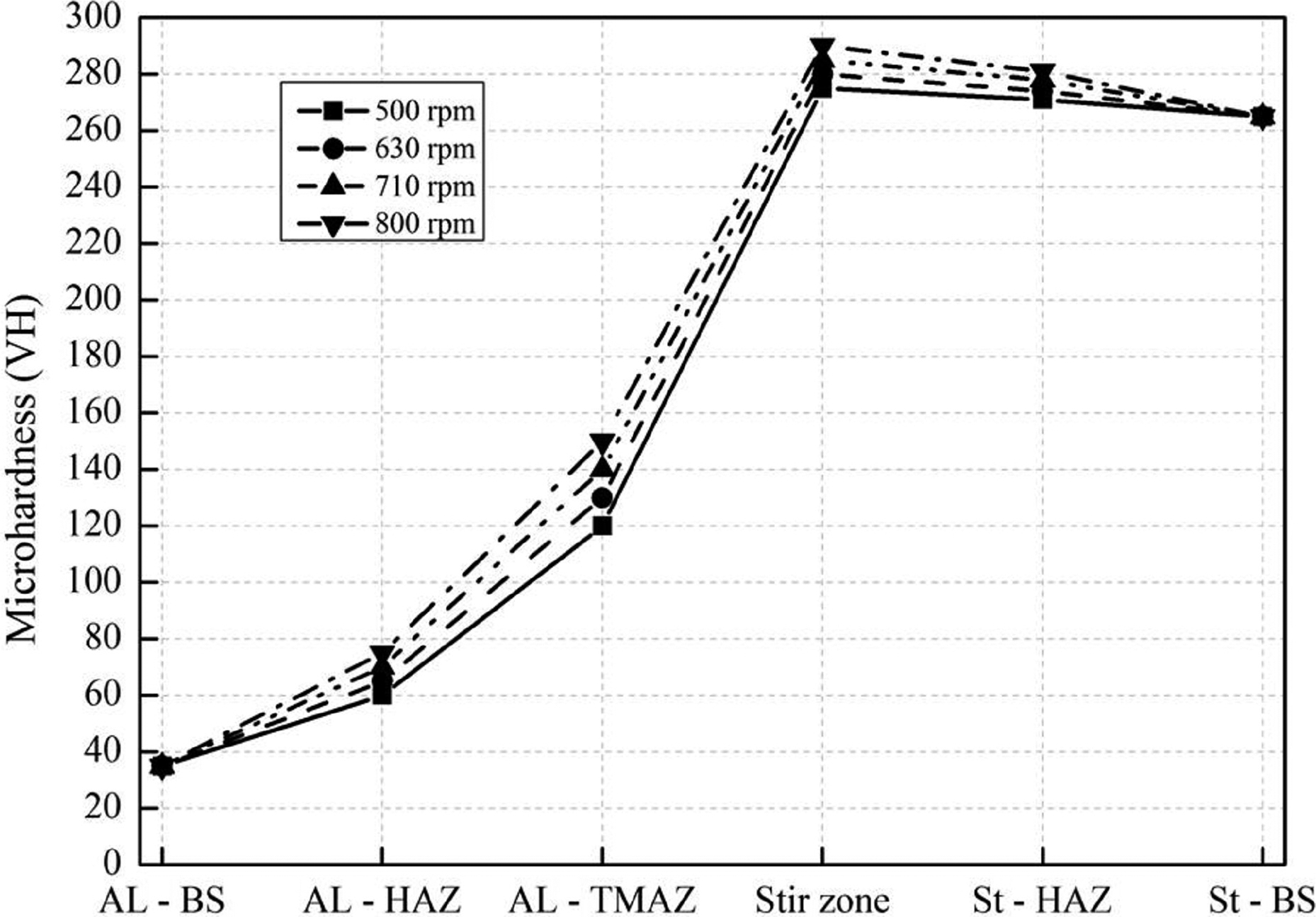
Microhardness profile versus rotational speed (63 mm min− 1 traverse speed, 0.2 mm plunge depth, tool offset of 1.3 mm and 2° tilt angle)
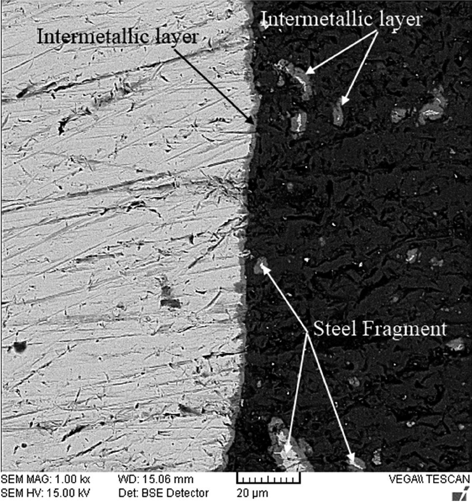
Stir zone SEM image of sample welded by 500 rev min− 1 and 25 mm min− 1 (0.2 mm plunge depth, tool offset of 1.3 mm and 2° tilt angle)
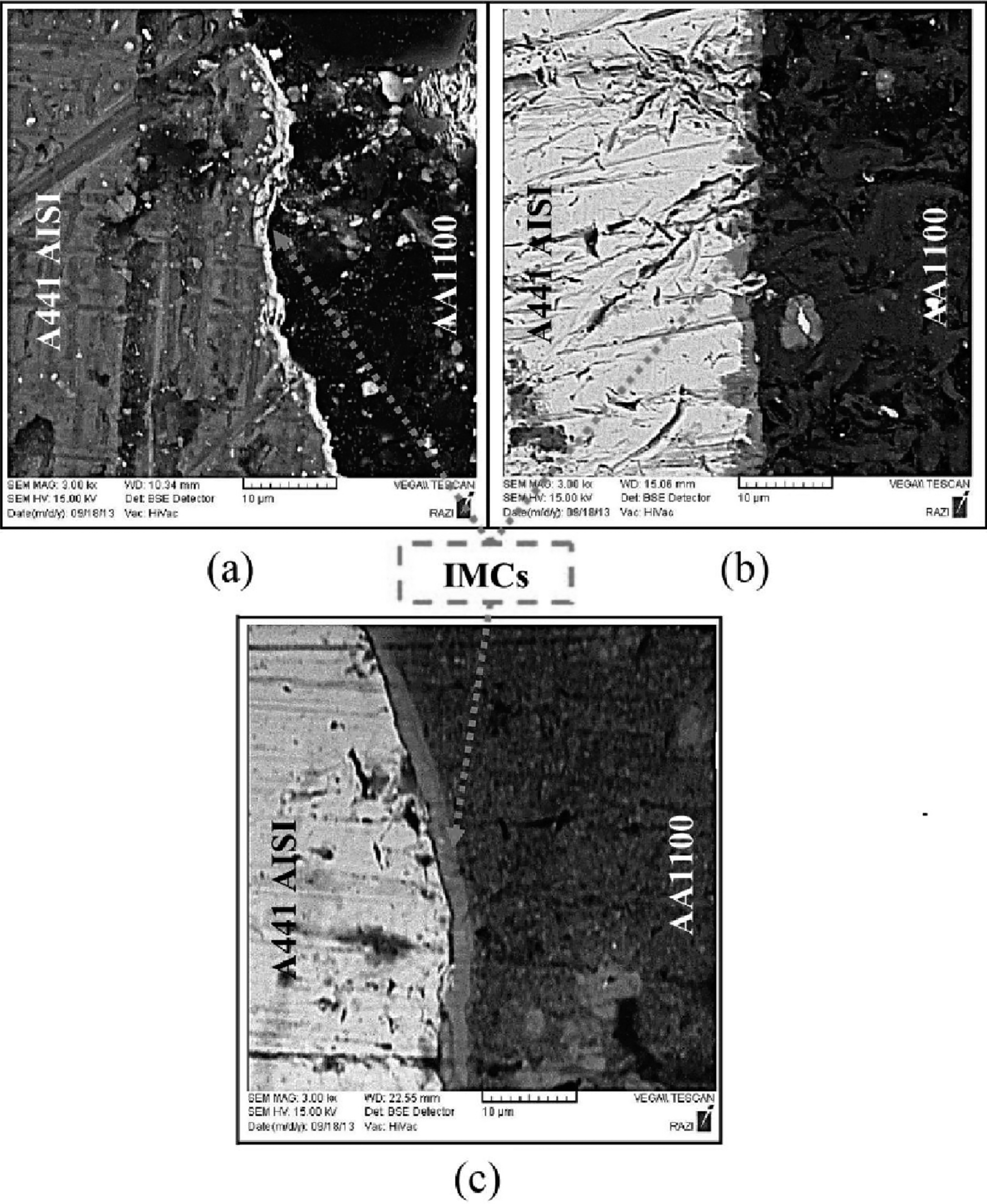
Intermetallic compounds in joint interface of samples welded by 63 mm min− 1 and a 500 rev min− 1, b 630 rev min− 1 and c 800 rev min− 1 (0.2 mm plunge depth, tool offset of 1.3 mm and 2° tilt angle)
Conclusions
In this research, AA1100 aluminium alloy and A441 AISI steel was successfully welded by the FSW process. The results of the investigation on mechanical properties and material flow of these joints are presented as follows:
Among the selected offset, it was found that the best pin offset is 1·3 mm in the aluminium side, while the heat generated and the plasticised aluminium flow in the 0·8 mm offset were not appropriate. On the other hand, at offset >1·3 mm, smaller volume of pin tool was placed in the steel side, and subsequently, the tool did not enable the deformation of the steel. The most appropriate material flow and joint strength were achieved in 0·2 mm plunge depth. The joints that were produced in 0·1 mm plunge depth had not enough strength, and the joints that were welded in >0·2 mm plunge depth had inappropriate internal plastic flow. By increasing welding speed from 25 to 80 mm min− 1, tool forging force within the plastic material increased, and this event resulted in better material flow and fabrication of defect free joints. With the increase in rotational speed, the thickness of intermetallic compounds that were formed in the material interface increases and the joint microhardness increases.