
Abstract
API X80 pipeline steel is widely used in natural gas and oil transportation. In this study, X80 pipeline steels with 18.4 mm thickness and 1219 mm diameter, made in China, were welded by a combined girth welding technology. Experimental results showed that microstructures in weld metal and coarse grain heat affected zone are mainly composed of coarsening bainite grains with dimensions of 20–50 μm, and Vickers hardness in weld seam is lowered by the seven-pass welding process. Simulated results illustrated that repeatedly thermal cycles imposed by the combined multipass girth welding process easily result in softened weld joints. The predicted microstructures, phase compositions and hardness in weld metal are in agreement with the measured ones. The results could be applied to optimise this combined girth welding process and improve the weld quality of API X80 pipeline steel and even higher grade pipeline steels.
Introduction
The consumption of petroleum and natural gas has been increasing rapidly, and their further development and utilisation have been paid more attention both in China and throughout the world.1–3 Since most of drilled wells for natural gas and oil are located in the remote regions such as Siberia, Alaska, Tarim Basin, deep oceans, etc., pipeline steels applied to transport gas and oil over a long distance have become thicker and larger, and require high strength and toughness simultaneously to improve transportation efficiency under a high pressure condition.4, 5 Therefore, the pipeline construction plays an important role in safely transporting gas and oil from wells to consumers, and girth welding process is a key technology in the pipeline construction and maintenance.
Nowadays some pipeline projects such as Ruhrgas in Germany, Trans Canada pipeline in Canada, Cheyenne plains gas pipeline in the United States, etc., are already performed using American Petroleum Institute (API) X80 pipeline steel. 1 Since 2002, several West–East Gas Pipeline Projects have been invested by Chinese government, and API X80 pipeline steel is also widely used in these projects.6, 7 Owing to the limitation of Chinese geological conditions, welders' skill and welding equipment, a combined girth welding technology is commonly used in the field construction of oil and gas pipelines. With the backing support from an internal line up clamp, the first pass is welded by manual metal arc welding (MMAW) with low hydrogen electrodes, and other six passes are welded by gas metal arc welding (GMAW) with flux cored wires. This combined welding technology is not as fast as some developed mechanised welding processes,1, 2, 8–13 but the welding joints and the repair rates are comparatively satisfactory. 13
In this study, MMAW and semiautomatic GMAW in vertical down position were applied for the girth welding of API X80 steel pipes. The produced welds were tested and their microstructure and hardness characteristics were discussed in detail. For calculating the heat transfer in the combined girth welding process, two-dimension double elliptic heat source mode and three-dimension double ellipsoid heat source mode were applied to model the MMAW and GMAW processes respectively. The deposited metal for filling double V groove was appropriately simulated by an element deactivation and activation technique. 14 Temperature profiles and thermal cycles were numerically analysed as well. Finally, the simulated results were used to predict microstructure and hardness of weld metal, and the predicted results are in agreement with the measured ones.
Experiments and model development
Experimental welds
Two pieces of circular pipe with the diameter of 1219 mm and wall thickness of 18.4 mm were girth welded together. Figure 1 shows the geometry of double V groove. The root pass was joined by MMAW using 3.2 mm diameter electrodes (AWS A 5.1 E7016, made by Kobe Steel, Ltd.) and other passes, including one hot pass, four fill passes and one cap pass were welded by GMAW using 2.0 mm diameter self-shielded flux cored welding wires (AWS A 5.29 E81T8-Ni2, made by Tianjin Golden Bridge Welding Materials Group Co., Ltd). Table 1 gives the chemical compositions and mechanical properties of deposited metals. Preheating and interpass temperatures were strictly controlled in the range of 100–150°C. Table 2 gives weld heat input of each pass, which has been optimised for improving the quality of weld joint.
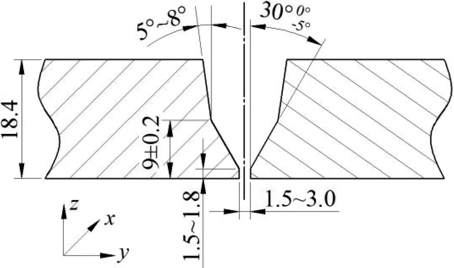
Schematic of double V groove joint preparation/mm
Chemical composition and mechanical properties of deposited metal
Average absorbed energy.
No details.
Weld heat input/kJ mm− 1
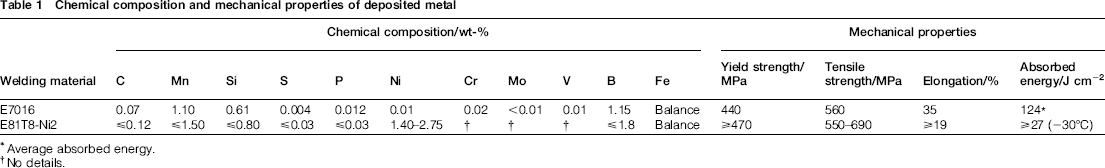
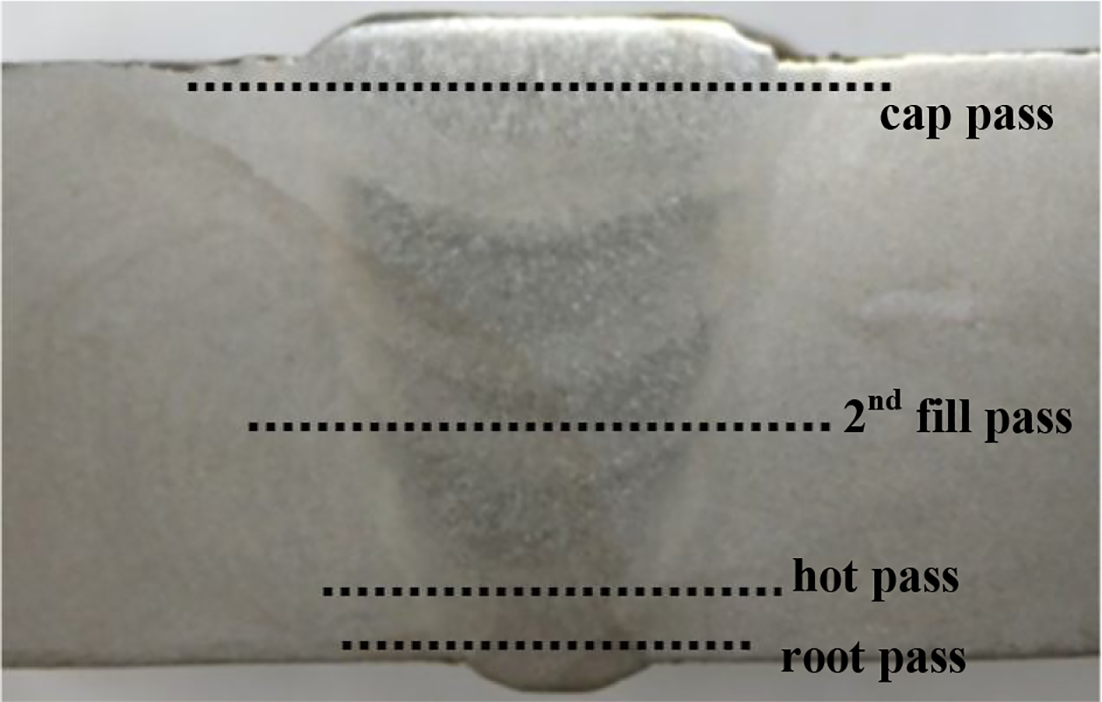
Two welders operated simultaneously, and each one welded half ring. The welding sequence was from top to bottom, i.e. the starting point and end point were at the highest point and lowest point of the circular pipe respectively. Figure 2 is the photograph of experimental pipes welded by combined girth welding technology. To observe the filling condition of all passes, each subsequent welding pass was shorter ∼200 mm than the former one. Figure 3 shows the macrophotograph of seven welding species after subsequently welding all the passes.
Pipes welded by combined girth welding process
Macrophotograph of welding species
Mathematical formulation
To describe the position along the circumference of steel pipes, it is normal to use the ‘clock-like method’, i.e. along the clockwise, the highest point of the circular pipe is defined as 12 o'clock position; subsequent points are defined as 1, 2, 3...o'clock ones in turn, and the lowest point of the circular pipe is defined as 6 o'clock position, and so on. Thus, the 3 and 9 o'clock positions are at extreme right and left sides respectively. From 10 o'clock position to 2 o'clock position of one pipe with the diameter of 1219 mm, the circumferential weld seam (∼957 mm length) can be simplified as plate butt welding.
Welding process models
As shown in Fig. 1, the root face depth is ∼1.5 mm, and the root gap is controlled in the range of 0–3 mm. Therefore, two-dimensional (2D) double elliptic heat source mode15–17 is employed to describe the heat input for root pass, which is shown in Fig. 4 and expressed as follows
Schematic of 2D double elliptic heat source mode (solid line)
If
 , then
 , then
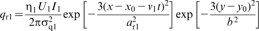
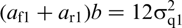
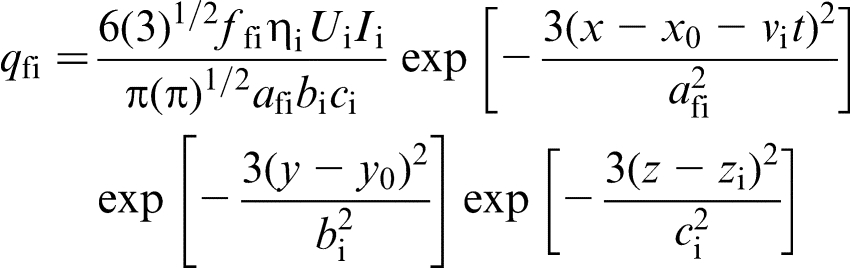
Three-dimensional double ellipsoid heat source modes,18–21 as shown in Fig. 5, are adopted to describe weld heat inputs for the other six passes welded by GMAW, and their expressions are as follows
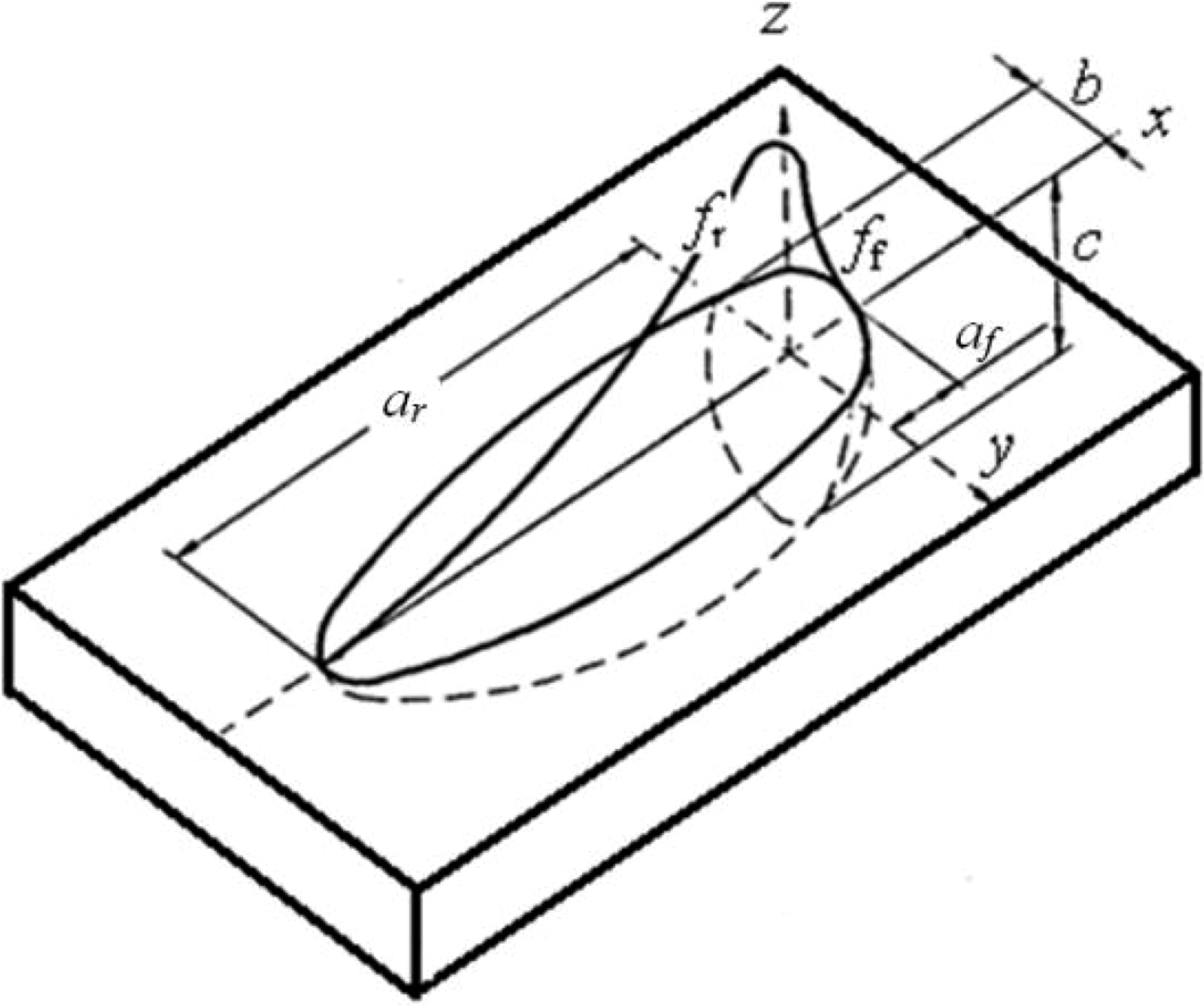
Schematic of 3D double ellipsoid heat source mode
If
 , then
 , then

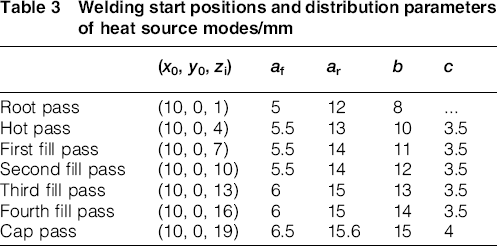
Table 3 lists the welding start positions and all the distribution parameters of heat source modes for each pass, which were used in the numerical simulation.
Welding start positions and distribution parameters of heat source modes/mm
Governing equation
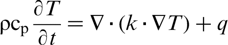
In this study, the numerical simulation was conducted using the commercial software ANSYS. The energy equation is written as follows
22
Boundary conditions
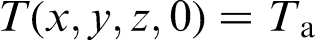
The initial condition is written as follows
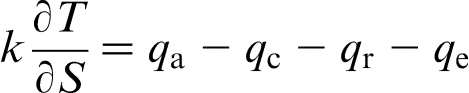
The energy on the free surface is balanced among the arc heat qa, heat dissipation by convection qc and radiation (qr) and heat loss due to evaporation qe.
23
Thus, the boundary condition is expressed as the following equation
 is temperature gradient in the normal direction of a workpiece surface. When simulation conducted by finite element software ANSYS, a total heat loss coefficient αj is used to deal with the boundary conditions, including convection, radiation and evaporation. Thus, equation (9) can be expressed as follows
Element deactivation and activation technique
To deal with the deposition metal from the filler wires, the transverse cross-section geometry of weld bead in each pass was prescribed as its actual profile, and its cross-sectional area is determined by the wire feedrate, wire diameter and welding speed. The element deactivation and activation technique14, 24, 25 were used to account for the filler metal deposition. First, the physical model was established according to the geometries of workpieces and groove, and a polygon is defined with proper dimensions corresponding to the cross-section geometry of weld bead and swept along the weld path. Then, all the elements inside the preset weld bead, that is the polygonal column, are deactivated before defining loads. At last, as soon as welding starts, a certain number of deactivated elements were activated in each calculating time step, until one pass was completely finished. This implies that the element birth and death options are used to deactivate or reactivate elements to consider the deposition metal from the filler wires.
Results and discussion
Microstructure
Figure 6 shows the schematic presentation of a fusion weld joint. As shown in Fig. 6, the heat affected zone (HAZ) can be divided into coarse grain HAZ (CGHAZ), fine grain HAZ (FGHAZ) and intercritical HAZ (ICHAZ). 26 Figure 7a through e show optical microstructure photographs of weld metal, CGHAZ, FGHAZ, ICHAZ and base metal for the second fill pass. From weld metal to base metal, grain sizes change evidently on the transverse cross-section of weld joint. In Fig. 7a and b, microstructures of weld metal and CGHAZ are mainly composed of bainite and small amount of ferrite. However, in Fig. 7e, microstructures of base metal are mainly composed of ferrite and small amount of bainite. Comparing with ferrite, bainite has higher carbon content and exhibits higher strength but lower toughness. Moreover, the observed bainite in this study was composed of grains with dimensions of 20–50 μm, whereas the base metal had a ferritic–bainite microstructure, which was uniform and fine with a mean grain size of no greater than 5 μm. Such coarsening grains decreased the toughness of weld seam, as reported by Gook et al.,8, 27 so the weld joints became more dangerous if the transportation pipeline serviced in the low temperature condition. Therefore, girth welding technology for API X80 pipeline steel is still a key issue and further investigations are necessary.
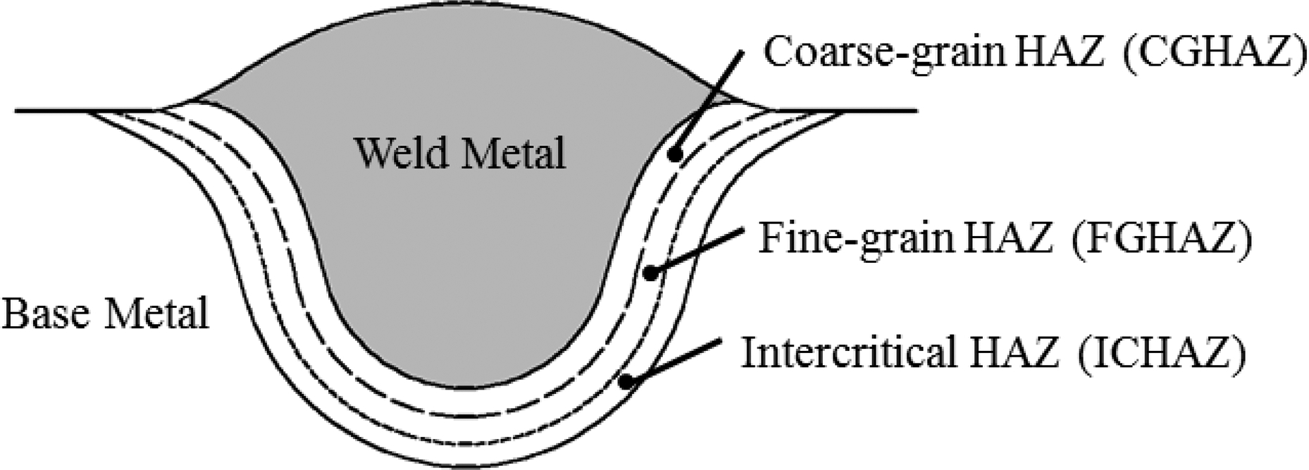
Schematic presentation of weld joint
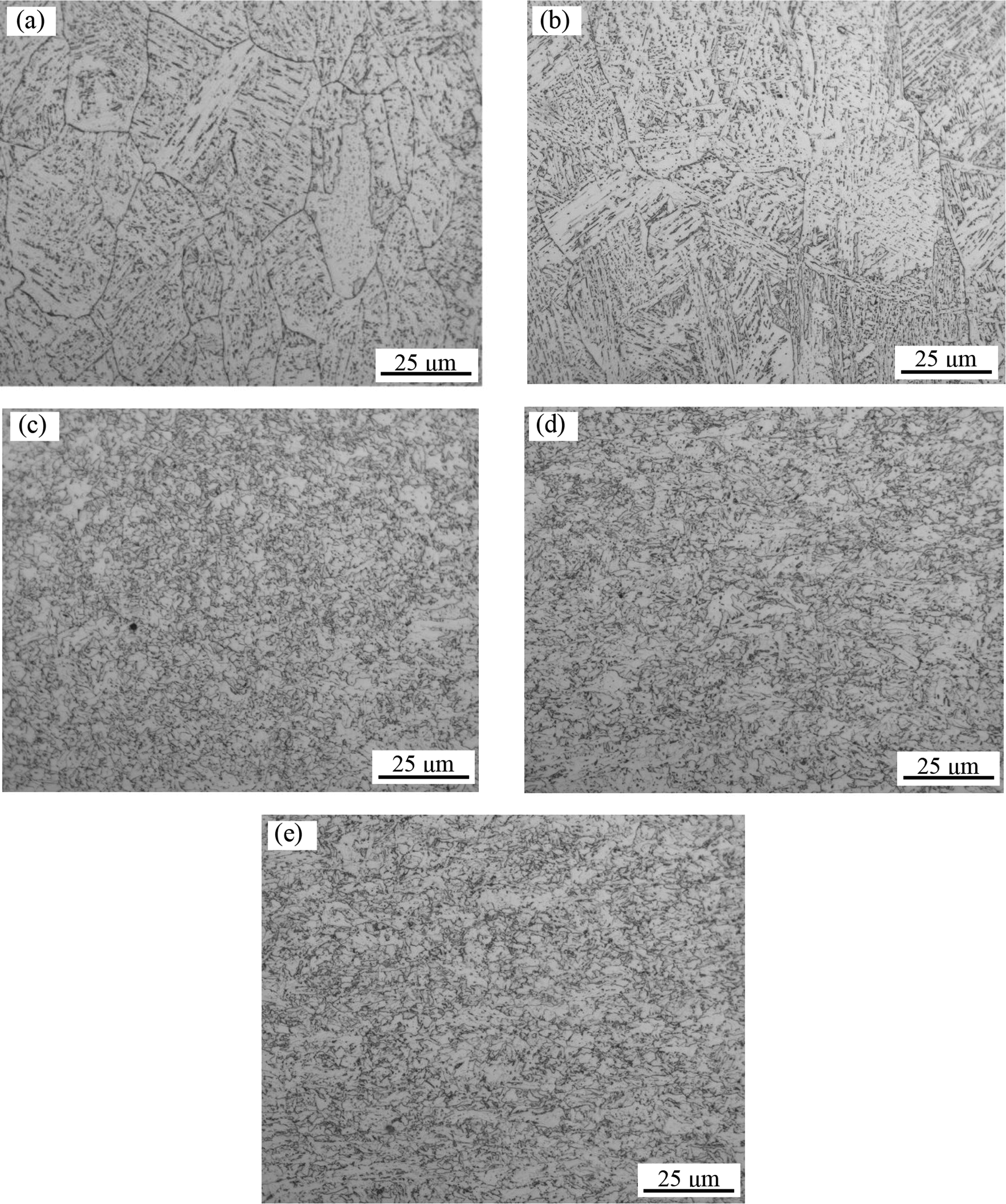
a weld metal; b CGHAZ; c FGHAZ; d ICHAZ; e base metal
Hardness measurement
Vickers hardness was tested using a 10 kgf load. The maximum deviation of the hardness measurements HV10 was ± 3%. Details to the location of the tested paths are illustrated in Fig. 8. The measured results of Vickers hardness for root pass, hot pass, the second fill pass and cap pass are depicted in Fig. 9. Comparing Fig. 9a with Fig. 9b through d, the measuring results of Vickers hardness for root pass are greatly lower than the other passes, because microstructures in weld metal and HAZ of root pass are mainly composed of ferrite, whereas microstructures in other weld metals and HAZs are mainly composed of bainite and small amount of ferrite. In Fig. 9, the mean hardness value in weld metal and HAZ is lower than the one in base metal. It can be concluded that weld seam is softened by the combined girth welding process.
Schematic of tested paths for Vickers hardness
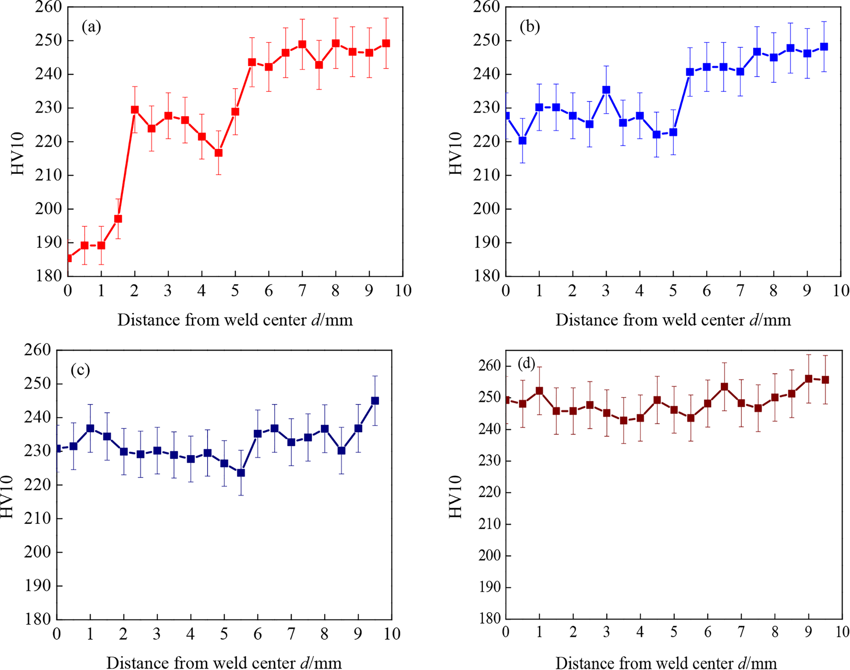
a root pass; b hot pass; c second fill pass; d cap pass
Temperature profiles
Figure 10 shows the calculated temperature profiles at longitudinal cross-section and top surface of the workpiece for different passes in quasi-steady state. With gradually filling the double V groove, the opening width of V groove gets larger, so the deposition amount per path from filler wire increases. In order to get sufficient deposition and avoid occurrence of weld defects such as incomplete penetration and undercut, the welding current is increased gradually, and the weaving frequency and amplitude of the welding torch are adjusted during practical welding process. Therefore, the deposition amount per unit length and unit time is increased gradually. In the scheme of numerical simulation programmed by ANSYS parametric design language, the variations of arc voltage, current and welding speed are directly taken into consideration, while the effects of torch weaving frequency and amplitude on the welding thermal process are indirectly treated by adjusting the distribution parameters of heat source mode and the heat generation rate in unit volume.
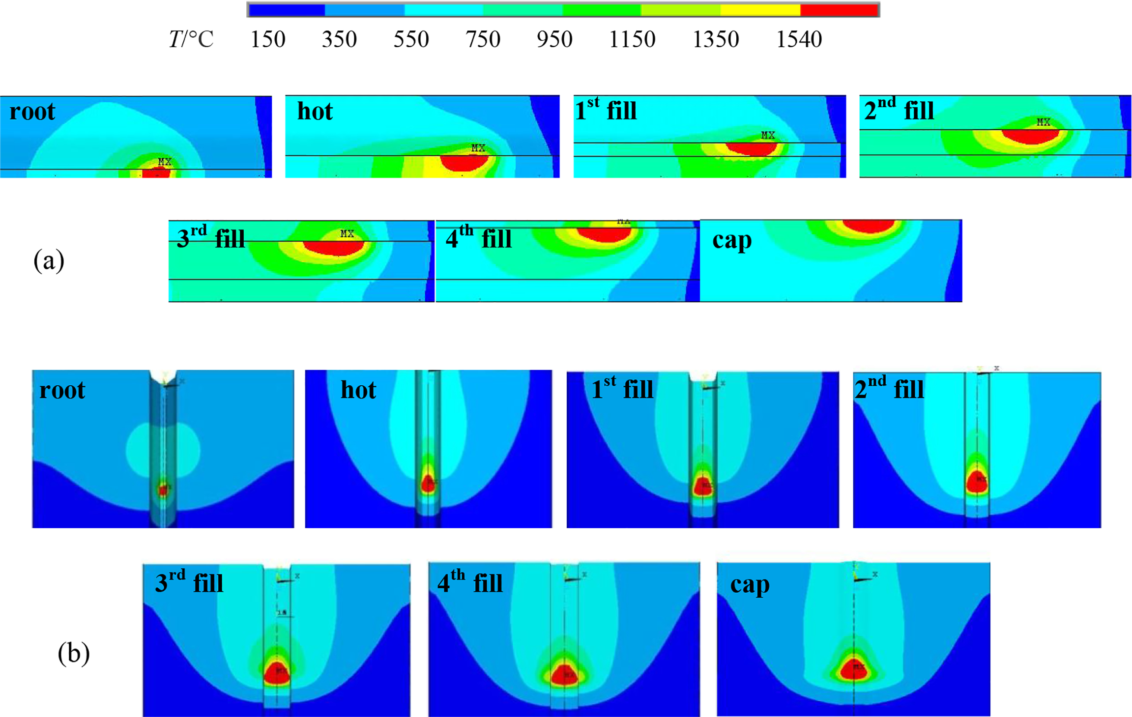
a temperature profile for each pass on longitudinal cross-section; b temperature profile for each pass, viewed from top surface of workpiece
Thermal cycles
Figure 11 shows the calculated thermal cycles of the two different points. In Fig. 11a, the position of point A was (0.075,0,0.001), so it was in weld metal of the root pass. Point A experienced seven thermal cycles, and all these peak temperature values decreased with increasing the number of welded passes. The maximum peak temperature was reached in the first thermal cycle when root pass was welded by MMAW. In Fig. 11b, the position of point B was (0.075,0,0.010), so it was in weld metal of the second fill pass. Point B also experienced seven thermal cycles, but its maximum peak temperature was reached in the fourth thermal cycle when the second fill pass was welded by GMAW. Analysing the values of the second peak temperature shown in Fig. 11a and b, it can be founded that both values overpassed 1150°C, which is austenite recrystallisation temperature of API X80 pipeline steel.28, 29 That is, in Fig. 11a, the grains in weld metal of root pass were reheated to austenite recrystallisation region and would recrystallise and grow, so these grains were coarsened when hot pass was welded. In Fig. 11b, grains in weld metal of the second fill pass were reheated and coarsened when the third fill pass was welded. Therefore, it was the latter high temperature thermal cycle imposed by subsequent welding pass that easily resulted in coarsening grains in weld metal, even in CGHAZ, as shown in Fig. 7a and b. On the other hand, decreasing weld heat input was an effective solution of suppressing grain coarsening.
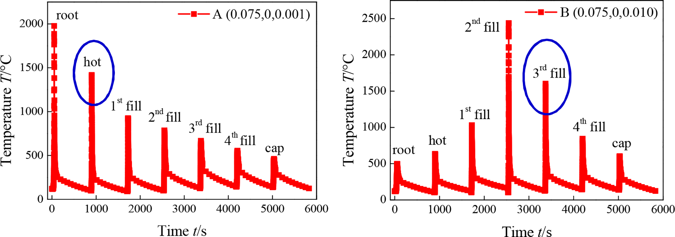
a point A positioned in root pass; b point B positioned in second fill pass
Predicting microstructure and hardness
Welding is a transient and non-uniform materials processing technology. Different point on the workpiece experiences different thermal cycles, so each one has its own cooling rate and t8/5 (cooling time from 800to 500°C), especially for points positioned in weld metal or in HAZ. Figure 12 shows thermal cycles of six nodes in the second fill pass. All the six nodes located in the fusion zone according to their positions are given in Fig. 12a and b. When welding process was in quasi-steady state, each one of these thermal cycle curves was similar to the others. Therefore, the calculated mean value of t8/5 is 17.875 s, and the mean value of cooling rate is ∼17.0°C s− 1. According to the CCT diagram for weld metal 30 shown in Fig. 13, predicted microstructure is composed of bainite and ferrite, and the volume fractions of bainite and ferrite are ∼94.5 and 5.5% respectively. In other words, the predicted microstructure for weld metal of the second fill pass is mainly composed of bainite and small amount of ferrite, which is in agreement with the experimental microstructure photograph shown in Fig. 7a. Furthermore, the predicted microhardness is in the range of 227–229 HV10, which are in agreement with the measured ones with 3% offset shown in Fig. 9c.
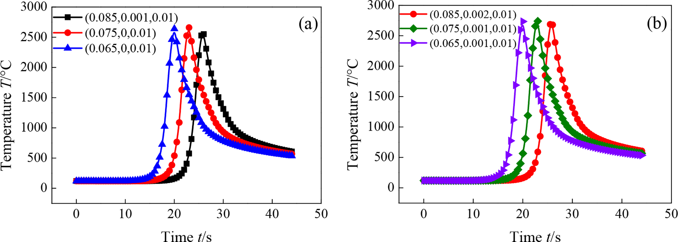
Calculated thermal cycles for six points located in weld metal of second fill pass
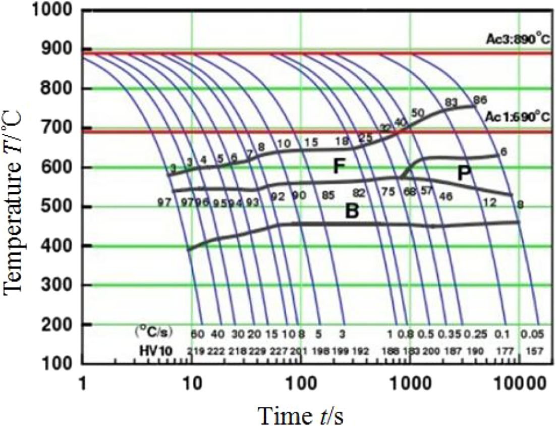
Diagram (CCT) for weld metal of X80 pipeline steel 30
Conclusions
The majority of phase composition was bainite in weld metal and CGHAZ, whereas the majority of phase composition was ferrite in base metal, and bainite in weld metal and CGHAZ was composed of coarsening grains with sizes of 20–50 μm, whereas ferritic–bainite microstructure in base metal was uniform and fine with a mean grain size of only a few micrometres. Heat input must be strictly controlled in welding of API X80 and higher grade pipeline steels. In the multipass girth welding process, imposed by the latter high temperature thermal cycle, grains in former weld metal and in former CGHAZ were reheated, recrystallised and coarsened when subsequent pass was welded, which resulted in softening weld joint. Novel and efficient girth welding processes need to be investigated to improve the weld quality of API X80 and other pipeline steels such as X100 and X120.31, 32 Based on the simulated results of temperature profiles and thermal cycles and CCT diagram for weld metal of API X80 pipeline steel, cooling rate and cooling time in weld metal were calculated, and microstructures, phase compositions and hardness were predicted, which are in good agreement with the experimentally measured ones.
Acknowledgements
The authors are grateful for the financial supports from the National Natural Science Foundation of China (51305461) and the Fundamental Research Funds for the Central Universities (13CX02075A). The authors thank the staff of Welding Technology Center of Pipeline Science Research Institute of CNPC for their help.