
Abstract
Al alloy sheet was friction stir spot welded (FSSW) to galvanised steel sheet by a scroll grooved tool without probe. Tensile and fatigue tests had been conducted using tensile shear specimens, and the results were discussed in comparison with Al/steel dissimilar FSSW joint, in which steel sheet was not galvanised. Energy dispersive X-ray analyses revealed that Zn coating was melted or softened and circumferentially resolidified around the nugget. Intermetallic compound between Al and Fe was formed along the interface resulting in the joining of Al to steel. Tensile shear strength of Al/galvanised steel weld was lower than that of Al/steel one without galvanising. However, Al/galvanised steel welds exhibited higher fatigue strengths. Finite element method analyses around the nugget revealed that circumferentially resolidified Zn brought about the stress relaxation at the edge of the nugget, resulting in the better fatigue performance of Al/galvanised steel welds.
Introduction
Efforts of automobile manufacturers in reducing vehicle weights had been made due to the strong demands for better fuel consumptions. Maintaining the high strength/weight ratio is their ultimate goal in designing lightweight structures. These have led to the increasing utilisation of aluminium (Al) alloys to automobile components; meanwhile, steels are also utilised as used to be because of its high reliability, recyclability, economical efficiency and so on. Consequently, dissimilar spot welding between Al and steel is required in the manufacturing sector in order to achieve hybrid structures, and the weldability of those dissimilar alloy sheets had been widely investigated. Oikawa et al. applied conventional resistant spot welding for the joining between Al and steel sheets. 1 They had indicated that high joint strength could be achieved when aluminium clad steel sheet was used as an insert metal, while direct joining between Al and steel resulted in the formation of brittle intermetallic compound (IMC) layer along the interface and lower joint strength. Intermetallic compound layer can easily be formed along the interface between these dissimilar metals in conventional fusion welding. This cannot secure sufficient and reliable strength of joints because of brittle fracture mechanism of IMC itself. The problems encountered during Al/steel dissimilar welding were well summarised by Liyanage et al. 2 Consequently, friction stir welding has received attention from the view point of dissimilar welding. That is because friction stir welding is a solid state welding process, in which the formation of IMC could be controlled by changing process parameters. Thus, friction stir spot welding (FSSW) is also applicable to the dissimilar spot welding. The application of FSSW to Al/steel dissimilar welding had also been widely reported,2–8 and revealed that the joining was achieved by the formation of very thin IMC layer.2, 3, 5 Bozzi et al. 5 had reported that IMC layer thickness could be controlled by the process parameters and that tensile shear fracture load could be related to the IMC area fraction.
On the other hand, from the viewpoint of automotive industry, the material used is galvanised steel sheet for ensuring the safety and corrosion protection in the mechanical structures. Based on Zn–Fe–Al ternary phase diagram, 9 Zn and Al do not form IMC, while Al and Fe easily form IMC. Consequently, joining mechanism between Al and galvanised steel sheets had been studied.10–13 Miyagawa et al. 11 revealed that Zn coating was removed from the steel surface beneath the tool due to sever stirring of Al alloy, resulting in the formation of thin Al/Fe IMC layer along the exposed steel surface, and sound joining had been achieved. Gendo et al. 10 showed that the tensile shear strength of Al/galvanised steel FSSW joint decreased with increasing the solidus temperature of coating because of the difficulty of removing galvanised coating during stirring action.
To use FSSW joints for structural components, it is very important to understand their fatigue properties. Accordingly, the authors had performed fatigue tests using dissimilar friction stir spot welds and revealed their fatigue fracture mechanisms.6, 14 When Zn coating is removed from steel surface beneath the tool and remains around the nugget as Miyagawa et al. had mentioned, 11 stress state around the nugget could be changed, which leads to the different fatigue properties. However, the fatigue properties and fracture mechanisms of dissimilar Al alloy/galvanised steel friction stir spot welds are not clear. In this study, the dissimilar lap welds between Al alloy and galvanised steel sheets were fabricated by FSSW using a scroll grooved tool without probe, 15 and tensile shear fatigue tests were conducted. The fatigue strengths of these welds were evaluated, and fracture mechanisms were discussed based on microstructural, fractographic and stress analyses around weld zone.
Experimental
Materials and specimen configuration
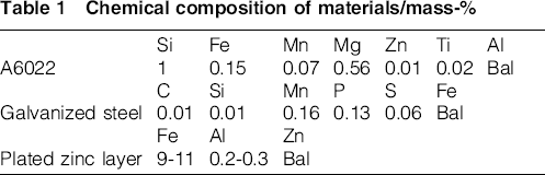
Automotive standard galvanised steel (SGCA) and Al (A6022-T4) alloy sheets were used to fabricate dissimilar welds, whose thickness was 1.4 and 2.0 mm respectively. The chemical compositions of the base materials and plated Zn layer are summarised in Table 1. The microstructures of Al alloy and galvanised steel on the cross-section are revealed in Fig. 1. Al alloy exhibits equiaxed grains with the average grain size of 80 μm as shown in Fig. 1a. In the galvanised steel, ferrite–pearlite (with typical in carbon steels) structure is seen (Fig. 1b). Zn layer on the galvanised steel surface was observed by an optical microscope as revealed in Fig. 2, showing the Zn coating thickness of ∼8 μm.
Chemical composition of materials/mass-%

a A6022-T4; b SGCA
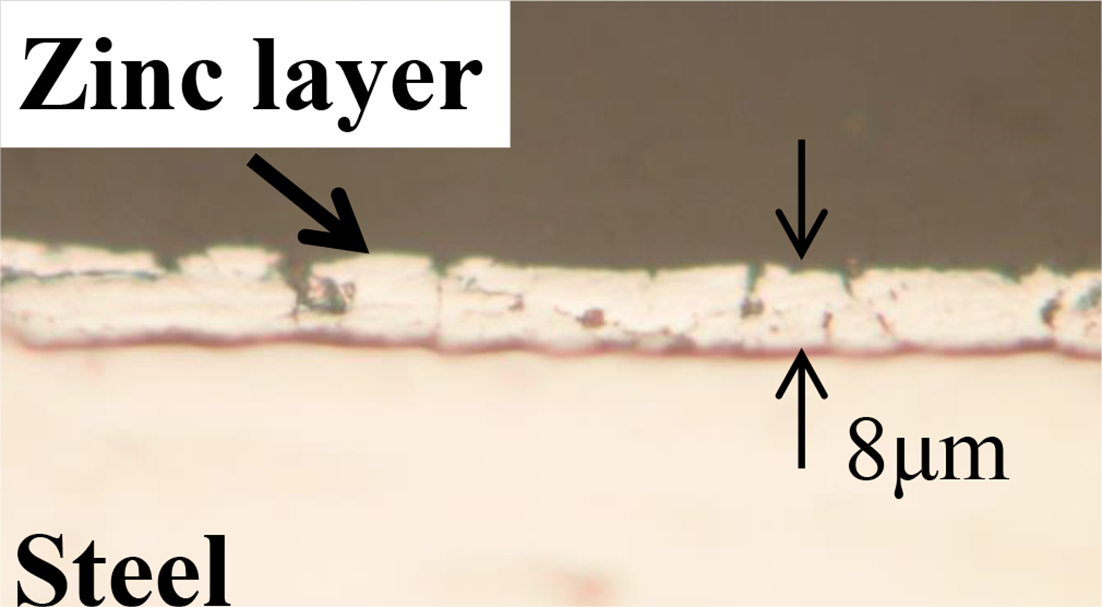
Plated zinc layer observed by optical microscope
The joint strength was evaluated using tensile shear lap specimen. Figure 3 shows the specimen configuration in accordance with Japanese Industrial Standard, JIS Z 3136. Specimens were made using two sheets, whose size was 40 mm × 150 mm. These two sheets were set with a 40 mm × 40 mm overlap area, where the upper and lower sheets were Al alloy and galvanised steel respectively.
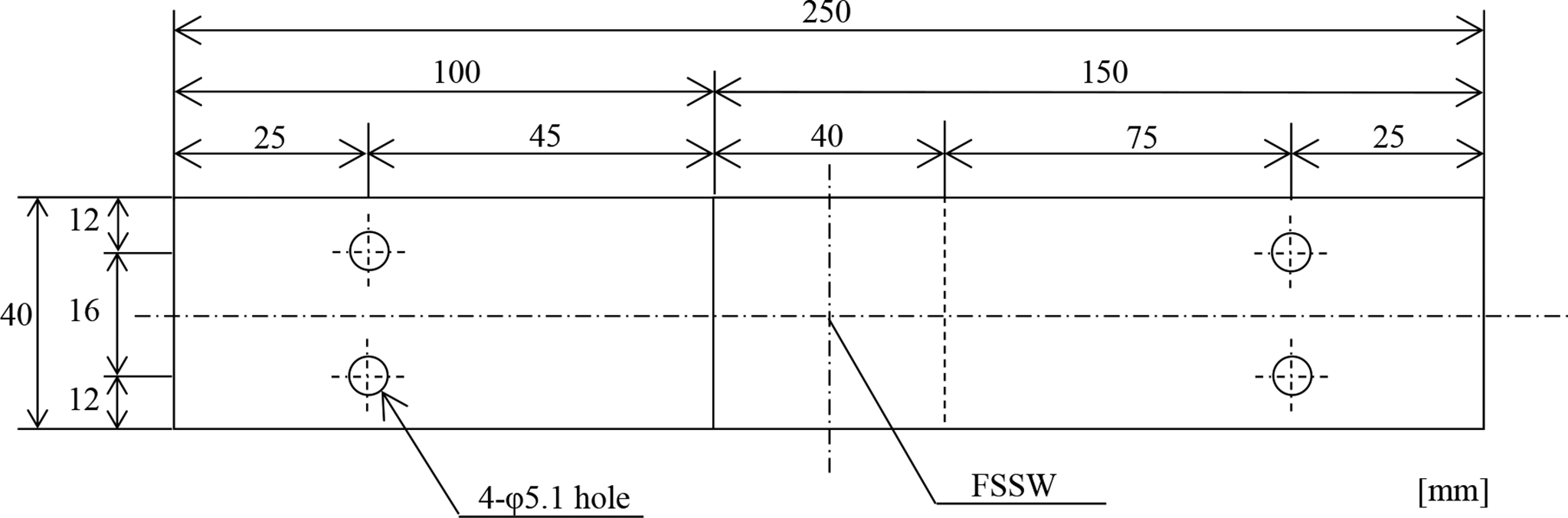
Lap shear specimen configuration
Tool geometry and welding conditions
The configuration of a scroll grooved tool without probe is shown in Fig. 4. The performance of this tool is described elsewhere. 15 It should be noted that the tool has no probe, but a 0.5 mm depth scroll groove on its shoulder surface. Al alloy and galvanised steel sheets were overlapped and tightly clamped. Then, the centre of the overlapped area was welded using Hitachi SHH204-718-719. Several combinations of process parameters were tried in which the range of tool rotational speed, dwell time and shoulder plunge depth were 1000–3000 rev min− 1, 5–8 s and 0.7–1.2 mm respectively. Based on the pretensile tests, the processing parameters were optimised as follows: tool rotational speed of 3000 rev min− 1, dwell time of 5 s and shoulder plunge depth of 0.7 mm, resulting in the tensile shear force of 3300 N.
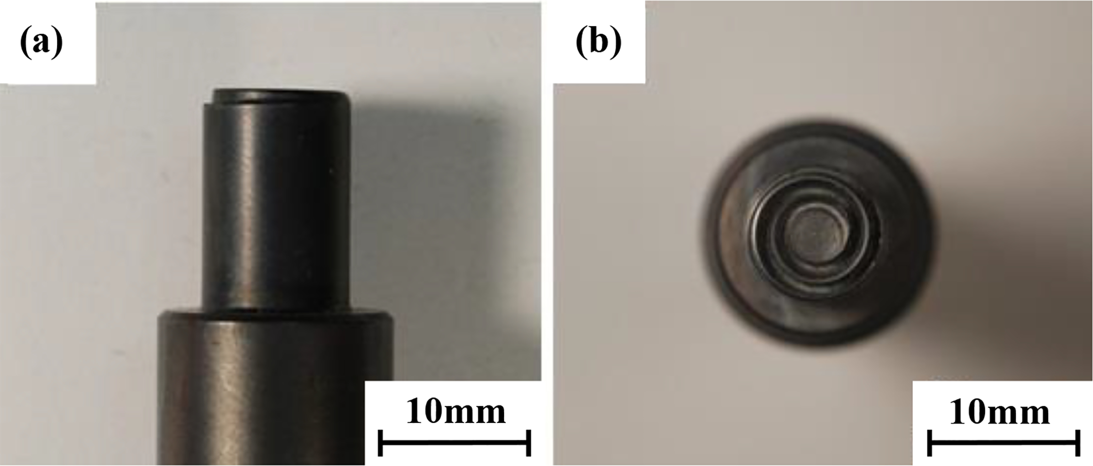
a side view; b bottom view
Experimental procedures
After the welding, the specimen was cut to get the cross-section for microstructural, hardness and energy dispersive X-ray spectroscopy (EDS) analyses. The cross-sections of the specimens were mechanically polished by emery paper followed by buffing using 3 μm diamond suspension. The hardness profiles on the cross-section were measured by micro Vickers hardness tester with a load of 4.9 N and a holding time of 30 s.
The static tensile shear tests were carried out by a universal tensile tester. The static tensile shear strength of the joint was evaluated using the mean value of five samples. The fatigue tests were conducted using an electrohydraulic fatigue testing machine under load control mode. The load wave form was sinusoidal with test frequency f = 10 Hz and load ratio R = 0.1. The failure criterion was defined as the final separation of test coupons, or the tests were stopped at 107 load cycles if no failure occurred. The fracture surface morphology and microstructures were examined by an SEM with EDS equipment.
Results
Microstructure in the weld nugget
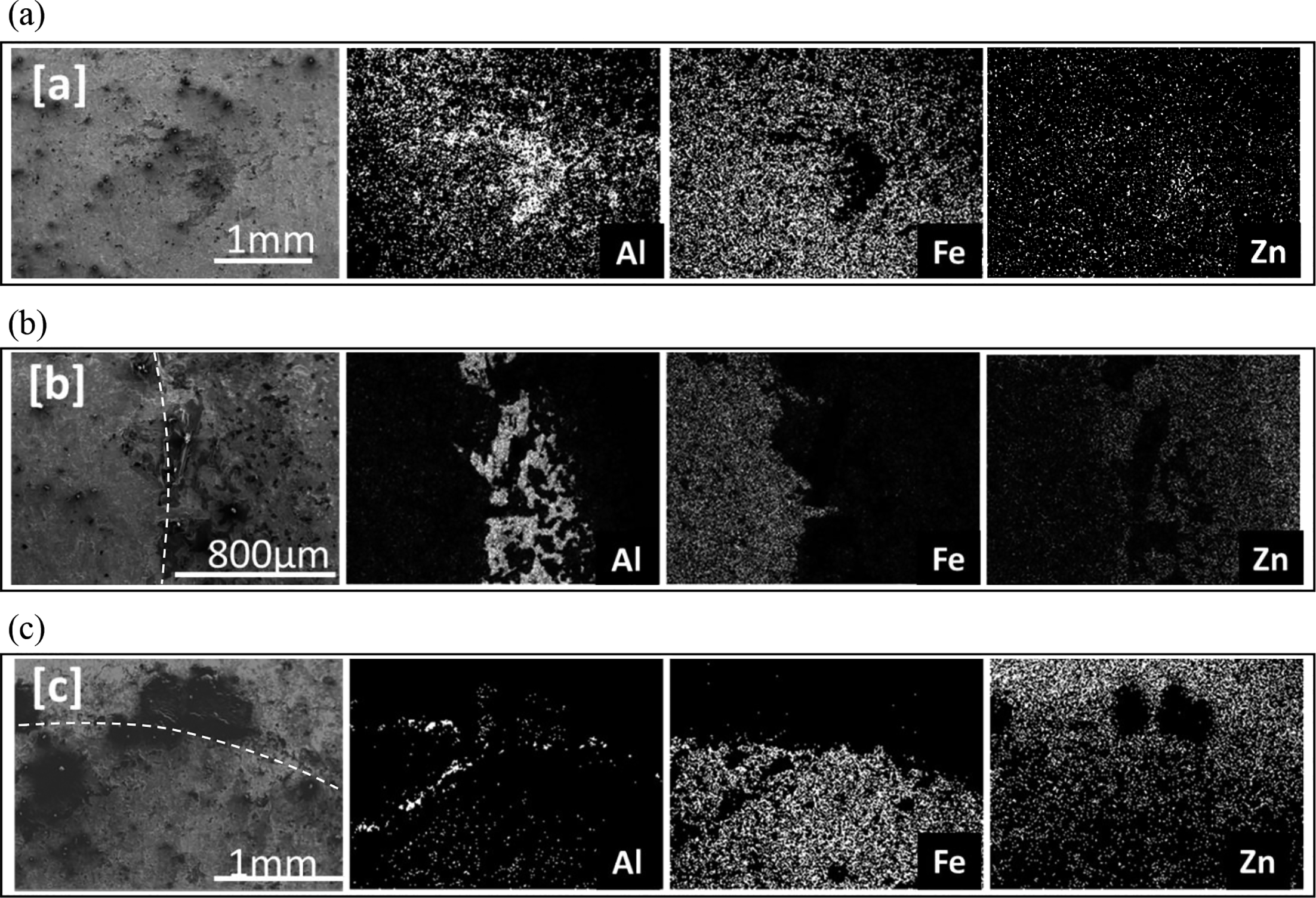
The macroscopic appearance of nugget cross-section is shown in Fig. 5a. The upper and lower sides are Al alloy and steel respectively. The interface between the upper and lower sheets is clearly seen and straight, which indicates that stirring of the material occurred only in the upper Al alloy sheet because the top of the tool did not reach steel surface. It should be noted that asymmetric grey layers are recognised in Al alloy sheet as shown by the arrows in Fig. 5a, and the magnified view of Fig. 5b. Figure 6a indicates the magnified view of the interface between upper and lower sheets near the centre of the nugget. The light grey band with the thickness around 1 μm is recognised along the interface. Energy dispersive X-ray spectroscopy line analysis was performed along the line shown in Fig. 6a, and the result was shown in Fig. 6b. Both Al and Fe are recognised across the light grey layer, which indicates that IMC layer was formed along the interface. However, Zn was not detected at the interface. Figure 7 reveals EDS maps in the areas ‘A’, ‘B’ and ‘C’ in Fig. 5a. It should be noted that the magnifications are different among those analyses. Zn is detected along the asymmetric grey layer in the area ‘A’ as shown by Fig. 7a. In the area ‘B’ (Fig. 7b), both Al and Fe are seen along IMC layer in accordance with the line analysis shown in Fig. 6. Figure 7c (area ‘C’) shows the edge of the nugget, and it indicates that Zn remains circumferentially around the nugget.
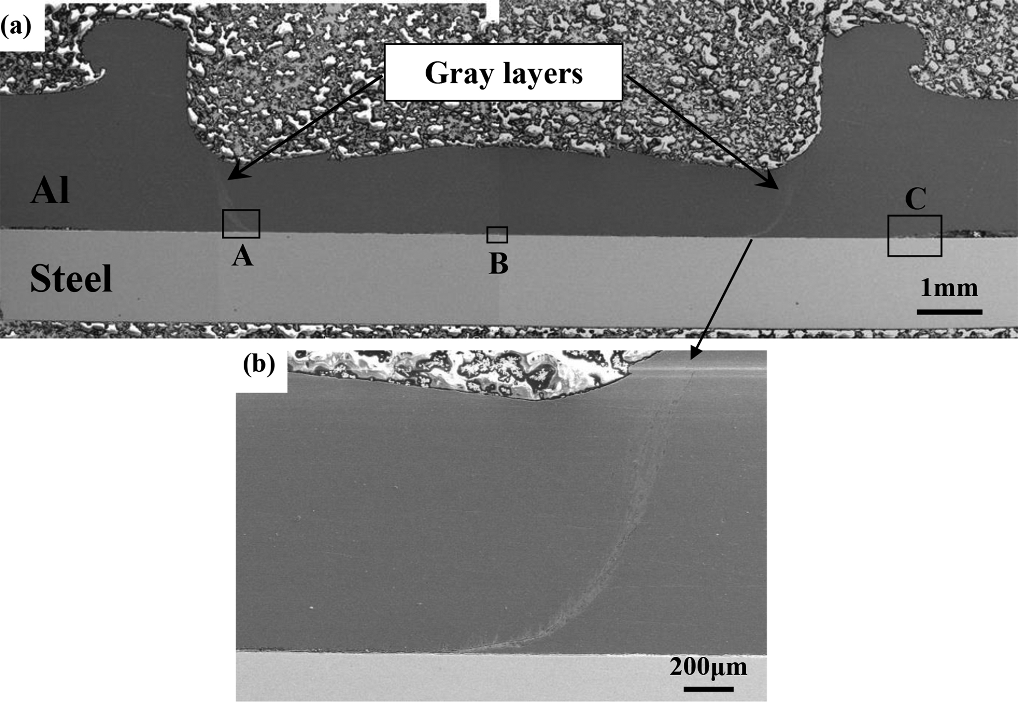
a macroscopic appearance; b magnified view of gray layer
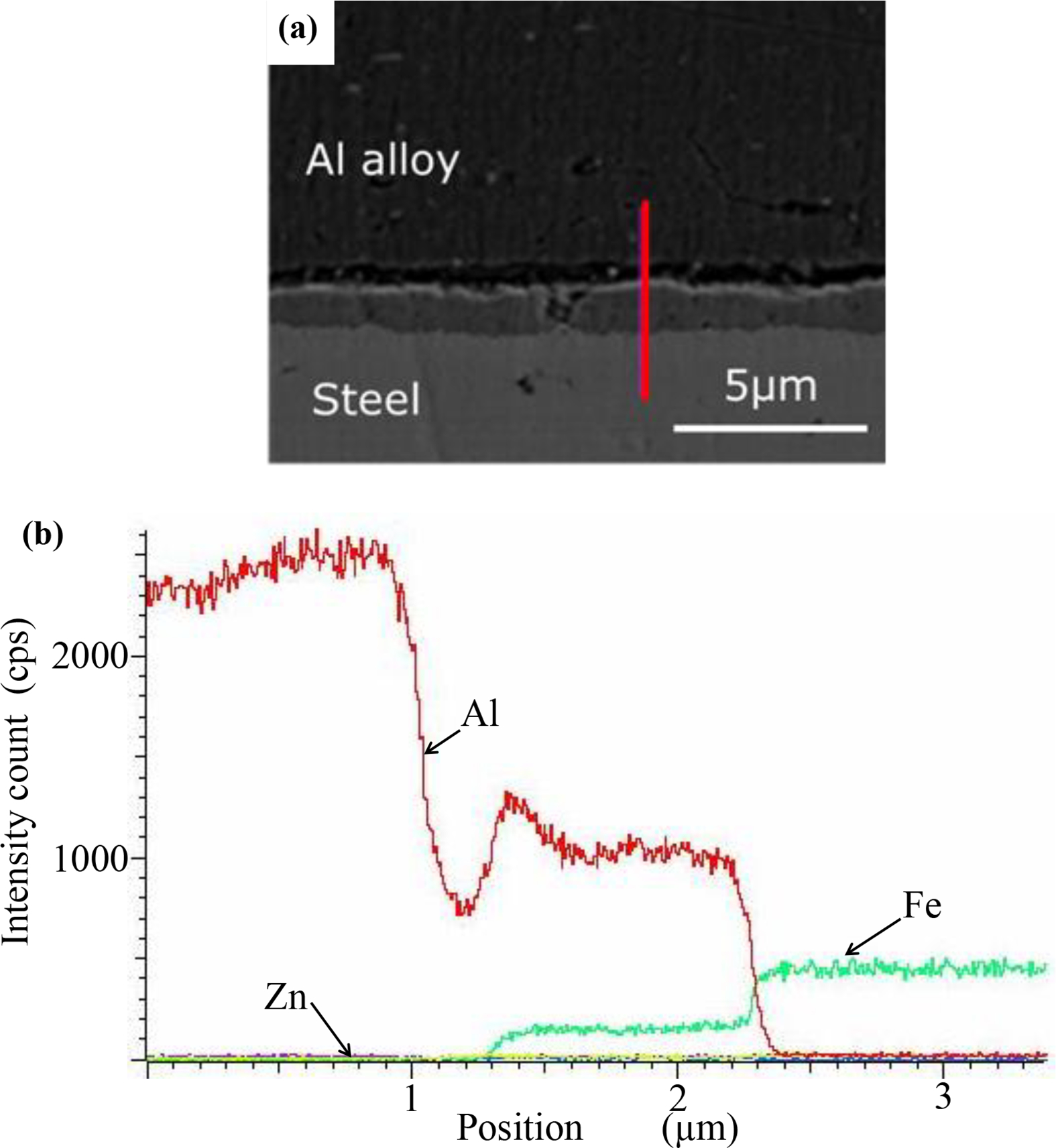
a image (SEM); b EDS analysis along red line in a
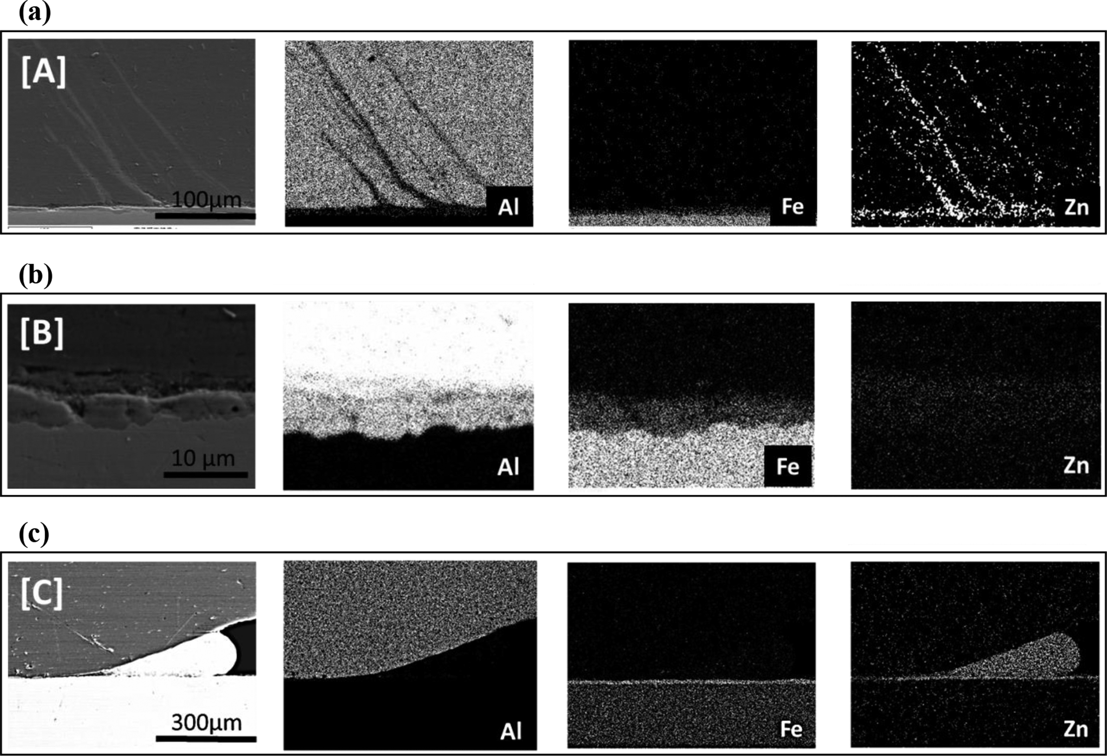
a area ‘A’; b area ‘B’; c area ‘C’
Feng et al. had measured the temperatures during FSSW between Al alloy and galvanised steel sheets, and revealed that the interface temperature reached 430 and 350°C near the centre and edge of nugget respectively. 12 It is considered that Zn coating was melted or highly softened beneath the tool because the melting point of pure Zn was 419.5°C. Gendo et al. had pointed out that Zn should not be completely melted to be removed from the steel surface. 10 Consequently, it is considered that melted or softened Zn coating was removed beneath the tool and Zn was circumferentially remained around the nugget as shown in Fig. 7c and partially moved upward as shown in Figs. 5b and 7a. At the same time, the motion of Zn from the centre to edge of the nugget during stirring process left a newly exposed steel surface. Then, IMC layer was formed between Al alloy and steel interfaces resulting in the joining of dissimilar alloys. The quantitative EDS analysis of IMC layer revealed that the atomic ratio of Al and Fe was about 3.2:1. Some papers concerning the nature of IMC layer in Al/steel dissimilar welds indicate that Fe3Al, FeAl, FeAl2, Fe2Al4 and FeAl3 could be formed near the bonding line depending on the welding procedures. 2 Based on the quantitative analysis, it is assumed that the IMC layer mainly consists of FeAl3 in the present case. In addition, Zn was hardly detected in the IMC layer (Fig. 6b), indicating that Zn was not related to the formation mechanism of IMC.
Mechanical properties
The hardness profiles are shown in Fig. 8 as a function of the distance from the centre of nugget, where the hardness was measured on the cross-section of the nugget, and horizontally along the lines ± 10 μm from the interface. The average hardness of the base metals is shown by the dotted lines. The hardness in the SZ on Al side is higher than the base metal (78 HV), while that in thermomechanically affected zone is slightly lower. The average grain size in the SZ is 10 μm, while that in the base metal is 80 μm. In addition, the base material had not been fully hardened in the as received condition, because the initial T4 treatment was natural aging. Consequently, the higher hardness in SZ could be attributed to the grain refinement, and the lower hardness in thermomechanically affected zone is due to the dissolution of fine precipitations or over aging. 16 Similarly, the hardness on steel side is higher than the base metal (120 HV) near the centre of nugget. Steel was not directly stirred by the tool, but the hardness profile on steel side was measured just below the SZ on Al side (10 μm from the interface). Accordingly, workhardening was induced near the interface by sever stirring on Al side and resulted in the slightly higher hardness of steel than base metal near the centre of nugget.
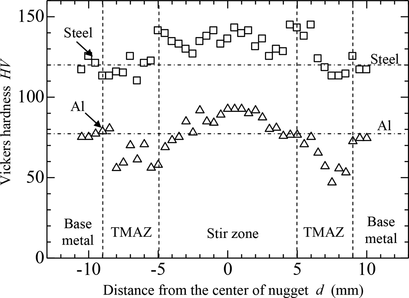
Vickers hardness profiles on cross-section of nugget
The average static tensile shear force of five samples was 3300 N as mentioned above. The macroscopic fracture surfaces under quasi-static loading are shown in Fig. 9, where Al side and steel side fracture surface is Fig. 9a and b respectively. It indicates that the interface fracture occurred between Al alloy and steel sheets. On the steel side fracture surface (Fig. 9b), EDS analyses were performed at the areas ‘a’, ‘b’ and ‘c’ in Fig. 9b. Figure 10 shows EDS analytical results, where Al was detected on almost the entire area of the steel side fracture surface. Similar EDS analyses were also conducted on the opposite Al side fracture surface, and Fe was recognised on the fracture surface. It indicates that IMC layer remains on the steel side and Al side fracture surfaces, and static fracture had occurred through IMC layer. Zn was detected around the nugget (Fig. 10b and c), while very few near the centre of nugget (Fig. 10a) in accordance with Fig. 7b and c.
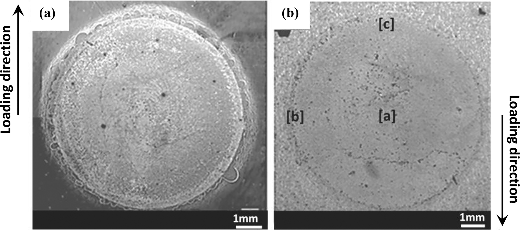
a Al side; b steel side
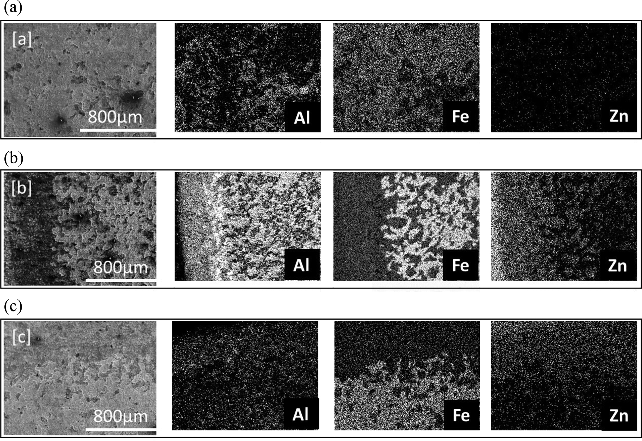
a–c areas ‘a’, ‘b’ and ‘c’ in Fig. 9b respectively
Fatigue strength
Figure 11 reveals the relationship between maximum tensile shear load Pmax and number of cycles to failure Nf. Fatigue limit of Al/galvanised steel dissimilar weld was 1250 N, which was defined as the run out load at 107 cycles. As a reference, the fatigue test results of A6061/A6061 similar and A6061/low carbon steel dissimilar welds fabricated by the same scroll grooved tool 14 are also plotted in the figure. In the case of Ref. 14, both Al alloy and steel sheets had the thickness of 2 mm, and the steel sheet was without Zn coating. The fatigue strengths of Al/Al similar and Al/steel dissimilar welds are nearly the same, 14 where the fatigue limit of Al/steel dissimilar weld was 800 N. It is clear that Al/galvanised steel dissimilar weld exhibits higher fatigue strength than Al/steel one without galvanising. However, it has been reported 14 that the tensile shear force of Al/steel dissimilar weld was 5400 N, which is higher than that of Al/galvanised steel one (3300 N). The difference of strengths between Al/steel and Al/galvanised steel dissimilar welds will be discussed in the next section. It should be noted the transition of fracture mode occurred in Al/steel dissimilar weld. 14 Namely, interface fracture between upper and lower sheets was dominant at high and medium load levels, while crack grew through the upper Al alloy sheet in the thickness direction at 1000 N as shown by the asterisk in Fig. 11. In Al/galvanised steel dissimilar welds, interface fracture was dominant through all load levels.
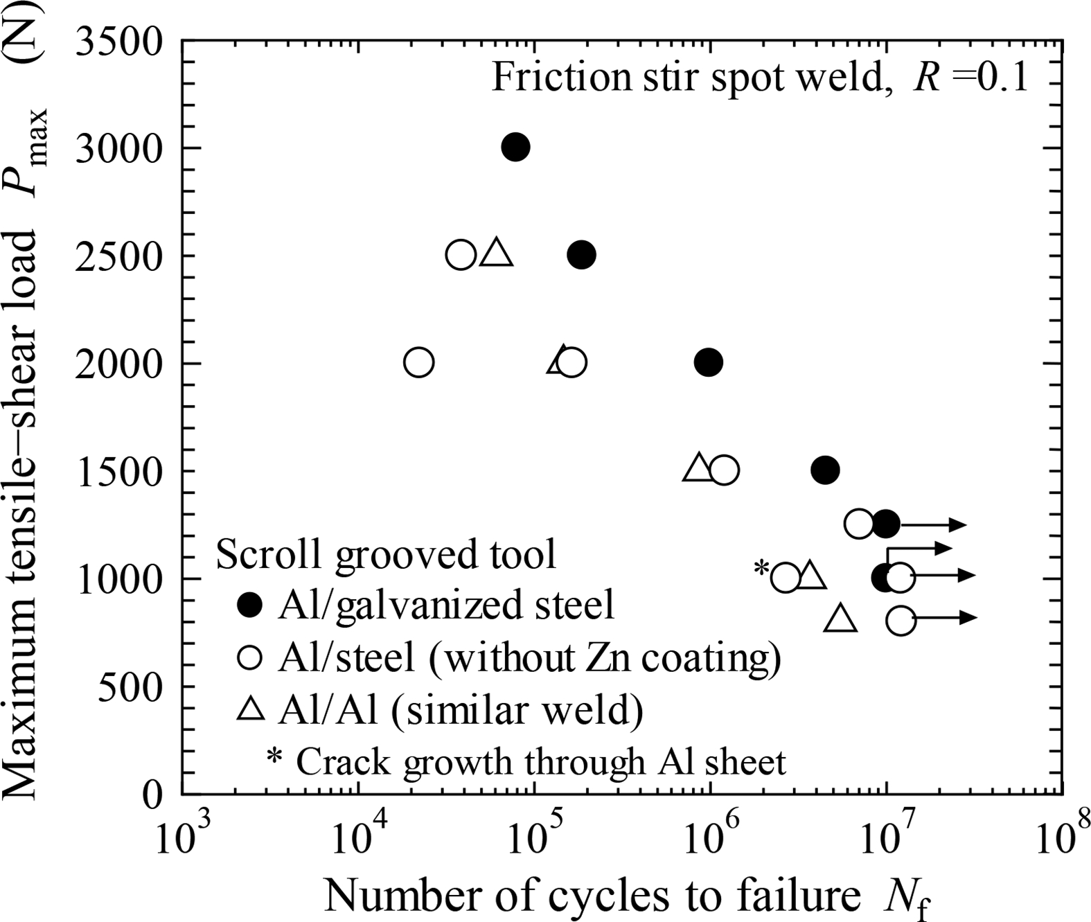
Relationship between maximum tensile shear load Pmax and number of cycles to failure Nf
Typical macroscopic appearances of fatigue fracture surfaces are shown in Fig. 12 (Pmax = 2000 N, Nf = 9.91 × 10⁵), where Al side and steel side fracture surface is shown in Fig. 12a and b respectively. The fatigue fracture occurred along the interface, and the failure mode seemed to be similar to that under static loading as shown in Fig. 9. However, a secondary crack initiated at the edge of the nugget and grew into the upper sheet as shown by the arrow in Fig. 12a. This secondary crack implies the possibility of the transition of fatigue fracture mechanism similar to Al/steel welds, 14 namely interface fracture to crack growth into Al alloy sheet. However, the transition did not occur in Al/galvanised steel welds.
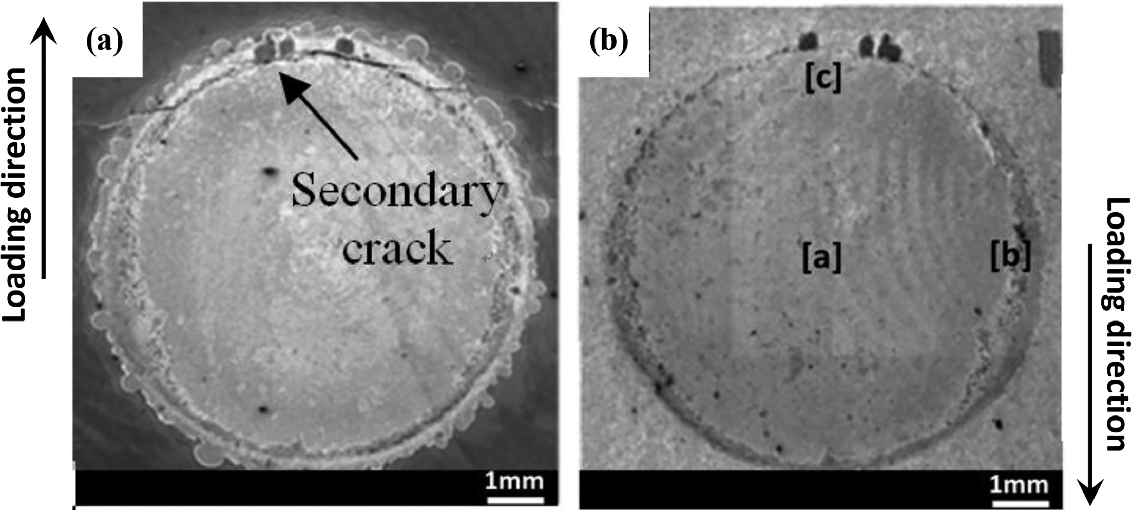
a Al side; b steel side
Subsequently, EDS plane analyses were performed at the areas ‘a’, ‘b’ and ‘c’ in Fig. 12b (steel side), and the results were shown in Fig. 13. Zn was mainly observed around the edge of the nugget (Fig. 13b and c) similar to the analyses on the static fracture surface (Fig. 10). In the area ‘a’ near the centre of the nugget, both Al and Fe are detected (Fig. 13a). The same area (near the centre of the nugget) was also analysed on the Al side fracture surface, and both Al and Fe were recognised. Accordingly, it could be concluded that the fracture occurred through IMC layer. However, in area ‘b’ (Fig. 13b), where left hand side from the dotted line is the fracture surface, and ‘c’ (Fig. 13c), where lower side from the dotted line is the fracture surface, namely near the edge of the nugget, the intensity of Al on the fracture surface side is weaker compared with Fig. 13a. In the same areas on the Al side fracture surface, both Al and Fe were detected through the similar EDS analyses. It indicates that fatigue fracture occurred along the interface between IMC layer and steel because Al was not left on the steel side. Fatigue crack growth of Al/steel dissimilar weld had been non-destructively investigated by a scanning acoustic microscope, and it was confirmed that fatigue crack initiated around the edge of the nugget and grew circumferentially towards the centre. 14 It means that the fatigue fracture should be dominant near the edge of the nugget, while the static fracture near the centre. Consequently, EDS analyses are similar between Figs. 10a and 13a because static fracture was dominant. It is considered that static fracture occurs through IMC layer (Figs. 10a and 13a), while fatigue crack grows along the interface between IMC layer and steel surface (Fig. 13b and c), indicating different microscopic fracture mechanisms under static and fatigue loadings.
a–c corresponds to area ‘a’, ‘b’ and ‘c’ in Fig. 12b respectively
Discussions
From the experimental results, it was found that the fatigue strengths of Al/galvanised steel dissimilar welds were higher than those of Al/steel ones, while the static strength was inferior in Al/galvanised steel weld. One of the reasons for the lower static strength could be attributed to the thinner plate thickness of galvanised steel (1.4 mm) than low carbon steel (2 mm). 14 The interfacial fracture occurred under static loading, namely share fracture as shown in Fig. 9. Thus, the thickness of the steel plate seems to be unrelated to the static strength. However, when the steel sheet with higher elastic modulus is thin, the rotation around the nugget easily occurs in the specimen configuration shown in Fig. 3 (lap shear specimen). 17 It is considered that the larger geometric rotation around the nugget had detrimental effect on the static strength in Al/galvanised steel weld. It should be noted that the effect of nugget rotation might be smaller under fatigue loading conditions because the applied loads were lower than the tensile shear fracture load. Furthermore, to join Al alloy sheet to galvanised steel, steel surface should be exposed by removing Zn coating for the formation of IMC layer as shown in Fig. 6. Figures 10 and 13 revealed that Zn was not fully removed from the steel side fracture surfaces, leading to the reduction in effective bonding area without Zn as schematically shown in Fig. 14. Thus, the lower effective bonding area in Al/galvanised steel weld could be the other reason for the lower tensile shear static strength.
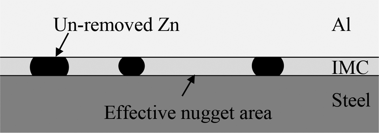
Schematic illustration of effective nugget area
Subsequently, the reason for the higher fatigue strengths of Al/galvanised steel welds is discussed. In general, fatigue life is classified into crack initiation and growth lives. Since fatigue crack initiates around the nugget in spot welds, the crack initiation is strongly dominated by the stress state around the nugget. Thus finite element method (FEM) analyses around the nugget and the effects of stress state on fracture had been investigated.18, 19 Daneshpour et al. 18 calculated stress state of spot welded coach peel specimen, and related preferred location for crack initiation to the stress distribution. Furthermore, Tanegashima et al. 20 had investigated fatigue crack shape around the spot weld nugget three-dimensionally and revealed that fatigue crack initiation life reached 60% of total fatigue life. It indicates that the crack initiation life should be important. Since fatigue crack initiates at the edge of the nugget,14, 20 the stress states around the nugget of Al/galvanised steel and Al/steel without Zn coating were evaluated by FEM. That is because the main difference is the presence of resolidified Zn layer around the nugget.
Two FEM models representing the edge of the nugget are defined as shown in Fig. 15 based on the actual geometry in Fig. 7c. In Fig. 15a, the geometry of resolidified Zn was modelled and classified as case 1. Then, dissimilar weld without resolidified Zn was also modelled for comparison as case 2 (Fig. 15b). Loads were applied at the edge of Al and steel sheets as schematically shown in Fig. 16, and von Mises stress profiles near the nugget on both sheet surfaces with and without resolidified Zn were also shown in that figure. These stress profiles are along the longitudinal cross-section of the welds. It should be noted that the stress concentration occurs at the edge of the nugget. As described in the fatigue fracture surfaces near the edge of the nugget (Fig. 13b and c), fatigue crack initiated and grew along the steel surface. Thus, we focused on the stress on the steel surface. As shown in Fig. 16, the stress on the steel surface is higher in case 2 than in case 1. It indicates that the presence of circumferentially resolidified Zn layer has resulted in the stress relaxation around the edge of the nugget. It could be concluded that this stress relaxation had resulted in the higher fatigue strengths of Al/galvanised steel welds. However, on the Al alloy side, the stress in case 2 is lower than in case 1 due to the presence of resolidified Zn. However, the crack initiated on the steel surface as mentioned above, and the stress on the steel surface should have dominated fatigue strength. It should be noted that the stress on the Al surface is higher on the left side, and this higher stress site corresponds to the secondary crack initiation site shown in Fig. 12a, indicating the validity of stress analyses.
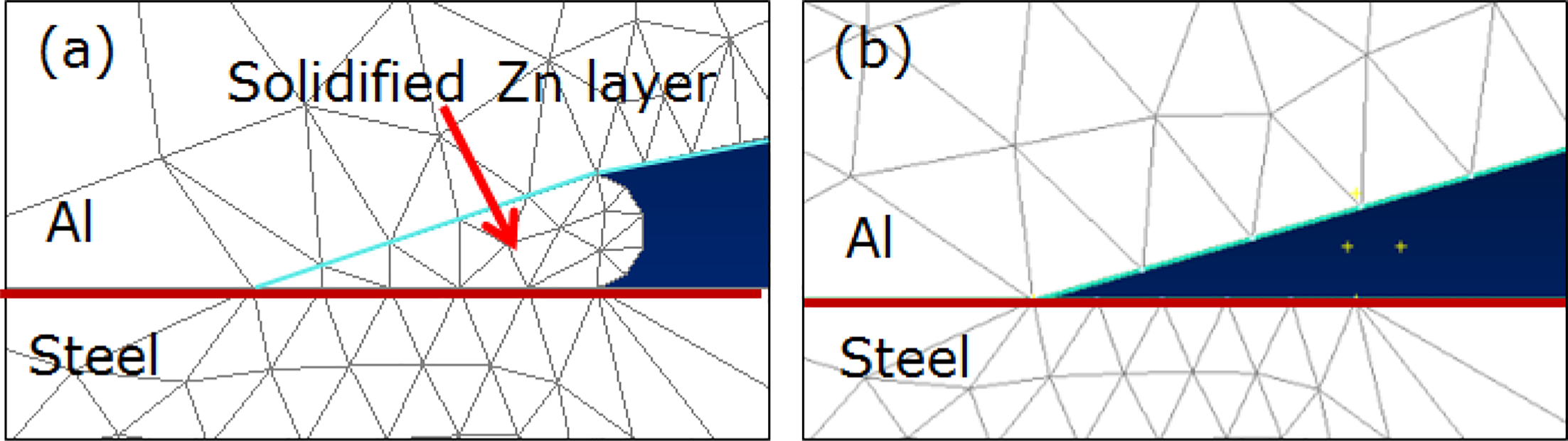
a with solidified zinc layer (case 1); b without solidified zinc layer (case 2)
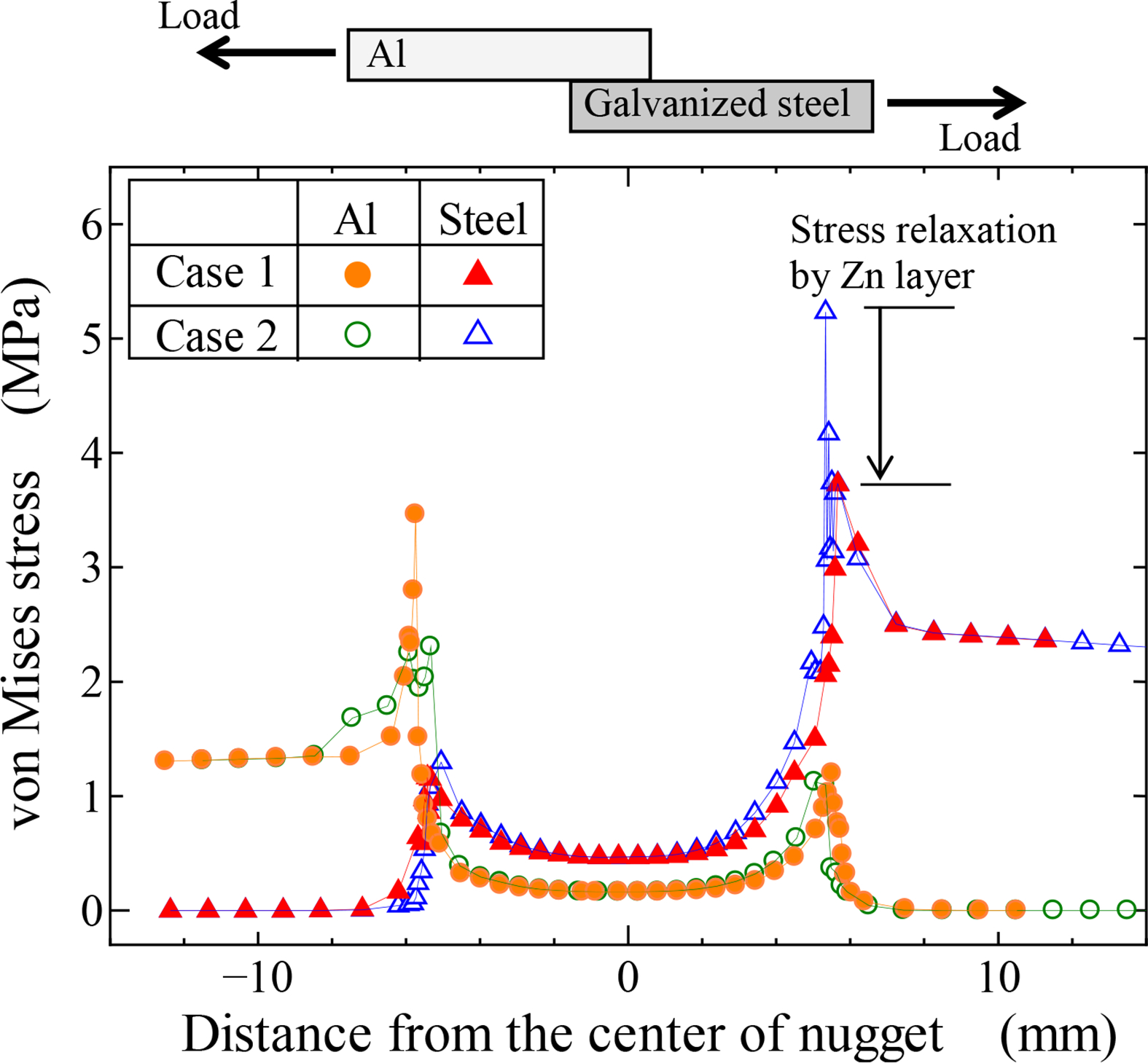
von Mises stress along interfaces of Al and steel sheets
High bonding strength between resolidified Zn and Al or steel could not be expected. However, as mentioned above, the fatigue loads were much lower than the tensile shear fracture load. In addition, generally, fatigue crack initiation mechanism is quite sensitive to the stress state around crack initiation site. For example, fatigue crack initiation is strongly affected by an inclusion in steel 21 or by a casting defect in Al alloy, 22 which are a few tens of micrometres in diameter. Consequently, it is considered that the stress relaxation induced by the resolidified Zn could be the main factor for the higher fatigue strengths in Al/galvanised steel welds.
Conclusions
Al sheet was joined to galvanised steel by FSSW using a scroll grooved tool without prove, and tensile shear fatigue behaviour of dissimilar weld was investigated. The following conclusions are drawn.
Zn coating was removed from steel surface due to melting or softening during stirring process, and Al/Fe IMC layer with the thickness of ∼1 μm was formed on the exposed steel surface without Zn coating. The formation of IMC layer resulted in the sound joining between Al and galvanised steel sheets. Removed Zn coating was circumferentially resolidified around the nugget. The tensile shear fatigue strengths of Al/galvanised steel welds were higher than those of Al/steel without galvanising, while Al/galvanised steel weld exhibited inferior tensile shear static strength. Based on the EDS analyses, fatigue crack initiated at the outer edge of the nugget and grew the interface between IMC layer and steel surface. The FEM analyses revealed that the circumferentially resolidified Zn induced stress relaxation around the nugget, and resulted in the higher fatigue strength of Al/galvanised steel weld than that of Al/steel one.
Acknowledgements
The authors wish to thank the Universiti Malaysia Perlis for their financial support. We would like to express our appreciation for the financial support from RING! RING! Project organised by Public Interest Incorporated Foundation ‘JKA’ (grant number 26-112).