
Abstract
In this work, the effects of the coating composition and the welding parameters on the heat generation and nugget formation during resistance spot welding of the hot press forming steels have been evaluated. Two types of coated steels were used, termed as Al–Si and Zn coating. Al–Si coated steel showed rapid nugget growth toward the electrode direction, which is the probable reason of the higher heat conduction from the electrode–sheet surface toward the bulk material. In Zn coated steel, heat was generated and localised at the faying interface and uniformly propagated to the steel substrate. High speed camera images showed that the presence of oxide at faying interface provides inhomogeneous current flow and violent heat generation in the Zn coated steel.
Keywords
Introduction
In recent years, automotive manufacturing companies are embraced to use high strength steels for weight reduction, high impact resistance and less CO2 emissions. Hot pressed boron steels have been developed to serve these purposes, which provide unique properties, such as no spring back effect, ultrahigh strength (ultimate tensile strength ≥ 1.5 GPa), etc. To ensure the corrosion protection issue, Al–Si based precoated hot press forming (HPF) steel was developed. Hot press forming steel is usually austenised in a furnace maintaining temperature between 900 to 930°C and hold for a period of 5–10 min; as a result, Fe diffusion occurs, and thereby, the coating transformed into several layers of intermetallic compounds; among these, the Fe–Al–Si layer existing between the coating and steel substrate has a thickness of about 5–7 μm.1–3 It has been reported that there are a total five layers; the first layer was identified to be Fe2Al5, which was followed by FeAl2 and Fe2SiAl2. Details of the coating microstructure can be found elsewhere. 4 Additionally, zinc based coating has been developed in Europe, which offers excellent scaling as well as cathodic corrosion protection. 5
In the last decades, researchers have dedicated their interest to develop microstructure, phase transformation diagrams and mechanical properties relationship of the HPF steels; limited information was obtained regarding heat treatment, coating process, formability and phase transformation.1, 4, 6, 8, 9 Apart from the microstructural analysis, proper joinability and weldability of the components must be ensured in order to commercialise the steel sheets. The joining of the press hardened steel by means of mechanical clinching is difficult due to the higher base metal strength; therefore, a short laser pulse is applied to heat up the sheets locally before or at the same time while clinching. 10 Resistance spot welding (RSW) is one of the fundamental joining process for automotive components, it being said that every automotive contains about 5000–8000 spot welds. The vital issue associated with the RSW of HPF steels is the composition and properties of the existing surface coating and oxides, which degrades electrode life and enhances surface and interface expulsion.4, 9, 11 Therefore, it is a matter of concern to remove the melted coating from the faying interface before nugget growth. Therefore, prepulse condition is sometimes considered to be an effective way to get the desired weld properties. 11 Hwang et al. 12 proposed to use a pulse current waveform to reduce the expulsion to weld Al–Si coated HPF. Jong et al. 13 evaluated the microstructure and mechanical properties of boron containing ultrahigh strength steel. Resistance spot weldability of dissimilar combination of 22MnB5 and GADP780 was investigated and reported by Choi et al. 14 Although surface coating of HPF steels solved the surface oxidation and decarburisation problem, the existence of the high surface coating introduces a high contact resistance, therefore degrading the spot weldability.4, 7, 15 In order to get the desired weld quality, a sandblasting or a dry ice cleaning process had been used to remove the coating before weld.5, 7, 11 Therefore, it has been granted that the coating properties are the main spot welding issue, which needs to be understood properly to obtain a high reliable weld properties.
In the present work, the spot welding characteristics of Al–Si and Zn coated HPF steels have been investigated by observing the nugget formation and heat generation. The nugget formation was monitored using a high speed video camera, as well as by cross-sectioning the nugget. The coating layer melting sequences, electrode degradation, elements distribution on the electrode tips and the effect of coating on expulsion behaviour have been evaluated.
Materials and methods
Materials
Two different coated HPF steels (thickness, 1.0 and 1.50 mm) were used in this investigation, which are termed as Al–Si coated HPF and Phs-ultraform Z140 (in this study, from here and onwards, Al–Si coated HPF and Phs-ultraform Z140 will be referred as Al–Si HPF and Zn HPF respectively). The chemical compositions and coating properties of both of the steels are shown in Table 1. It can be noted here that all materials used in this investigation were in hot stamped condition. The Al–Si HPF was austenised in a furnace to 900°C for 5 min and quenched through a metallic flat dies with a contact pressure of ∼40 MPa for 20 s; the temperature of the dies were about 40–50°C, as measured with a pyrometer. Zn HPF was austenised by the following similar procedure as of the Al–Si HPF. In non-hardened condition, coating thicknesses were about 9–13 μm, which were transformed to 15–30 μm as hardened conditions. Cross-sectional views and coating layer composition of both Al–Si HPF and Zn HPF are shown in Fig. 1.
Nominal chemical composition and coating properties of used hot pressed steels

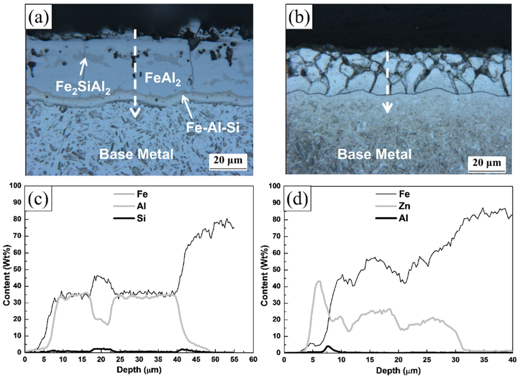
Optical micrographs and change of Fe, Al, Si and Zn concentrations in thickness direction of samples a Al–Si HPF and b Zn HPF; all of materials considered in present study were in hot stamped condition
Methods
The ISO 18728-212 16 was employed to evaluate the weldability, and detailed welding schedules are tabulated in Table 2. The welds were performed on a pedestal type medium frequency dc inverter spot welder with Cu–Cr dome radius type electrode (ISO 5821:2009) 17 under a constant water cooling rate of 6 L min− 1. Before weld, the Zn HPF steel undergoes a dry ice cleaning process to remove the oxide layer from the surface of the sheets, which lowered the contact resistance. 4 Dynamic resistance data between the copper electrodes were obtained from the machine readout software (Rexroth, Bosch Group, BOS6000 version: 1.35.2). For metallographic evaluation, samples were mounted and polished by the following standard metallographic procedure; the polished samples were etched with 4% nital (4%HNO3 on 96% ethanol) to reveal the microstructure. Stereo- and optical microscopes were used to perform microstructure observation. Furthermore, an electron probe microanalyser was used to get elements distribution information on the electrode tips as well as the faying surface of the welded coupons.
Resistance spot welding conditions used in experiments (ISO 18278-2) 16
A high speed camera was used to monitor the nugget growth; the monitoring system includes a processor, camera with different lenses, power supply, lighting sources, etc. Half cross-sectioned Cu–Cr alloy made 8.0 mm electrodes (dome radius type) were used to capture the nugget formation sequences. The electrode force (2.25 kN) and weld current (3.0 kA) were reduced to half of that of the original values (4.5 kN and 6.0 kA) as suggested elsewhere.18, 19 A 1.50 mm thickness of Al–Si HPF and Zn HPF steels was used to observe the nugget growth in a high speed camera; the front faces of the sheets were polished with 600 grade silicon carbide papers before the experiment. The sheets were placed between the two half sectioned electrodes, and the electrodes were brought into contact of the sheets with a predefined electrode force; afterward, a weld current was supplied to make the weld. To magnify and visualise the liquid nugget properly, a high speed camera was equipped with series of lenses: a combination of Nikon 200 mm, 1:1.4 D 50 mm, ultraviolet lens and an end filter. The images were captured at a rate of 2000 fps and shutter time of 1/6400.
Results and discussion
Effect of weld current
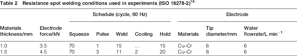
Owing to rich chemistry, high stiffness, high strength and complex microstructure, advanced high strength steels (including HPF steels) usually provide a narrow weld process window in contrast to mild and low carbon steels.20, 21 Figure 2 indicates the proportional relationship between the weld current and nugget diameter, i.e. nugget diameter increased with weld current; similar results were obtained elsewhere.9, 21, 22 An appropriate weld current was determined according to 4t1/2 condition (where t is the sheet thickness). 16 The graph also illustrates the effect of coating and the sheet thickness on the nugget size; a larger nugget was observed in the Al–Si HPF compared to the Zn HPF steel, regardless of the sheet thicknesses. Contrariwise, the sheet thicknesses greatly influences the expulsion (i.e. ejection of the metal from the faying interface, star symbols in Fig. 2) condition of the Al–Si HPF steel. It was noticeable that no weldable current range (current range between the nugget diameter equal to 4t1/2 to expulsion) was obtained in thinner gauge Al–Si coated steel. Before expulsion, Zn HPF provided a larger nugget diameter (1.0 mm sheets) compared to the Al–Si HPF, which is attributed to the effect of surface condition, as Zn HPF steel surfaces were dry ice cleaned. It can be noted here that thinner gauge sheets showed earlier expulsion compared to thicker gauge sheets. Electrode tip diameter is one of the influencing factors, which is inversely proportional to the heat input. As a smaller electrode tip (6.0 mm) was used to weld 1.0 mm gauge sheets, therefore, the contact diameter at the electrode/sheet (E/S) interface would be smaller compared to the larger electrode as used for thicker gauge sheets. As a result, the current density (ratio of the applied current to the contact area) will be higher; therefore, a high current density offered earlier expulsion, as expected. Throughout the study, a larger nugget diameter was obtained in the Al–Si HPF compared to the Zn HPF steel, and the nugget size differences were more pronounced when thicker gauge and higher weld current (above 6.0 kA) were used. The bulk resistance of the sheets is related to its thickness, as thicker gauge sheet has a higher bulk resistance compared to the thinner one. High bulk resistivity of the thicker gauge sheet allowed more heat to be generated; therefore, the nugget size would be larger at the same welding condition as depicted in Fig. 2. While heat was generated at the sheet/sheet interface, the thicker gauge sheet can sustain at a high heat; on the other hand, thinner sheets have less ability to withstand generated heat as the unmelted area around the molten nugget reduced; therefore, early expulsion could be expected.
Nugget diameters as function of weld currents
Weld nugget formation and growth
The presence of coating layer on the sheet surfaces can have adverse effects on the nugget formation. Generally, for welding of coated steels, a higher weld current, a longer weld time and a higher weld force are recommended by several researchers.23, 24 Unlike hot dipped galvanised or a hot dipped galvannealed, the coating layer on the HPF steel offers an additional resistance at the faying surface (F/S, the contact interface between the sheets), as well as at the E/S interface. The additional resistance influences the nugget formation and heat generation as can be seen in Fig. 3.

a Al–Si HPF (1.0 mm); b Zn HPF (1.0 mm); c Al–Si HPF (1.5 mm); d Zn HPF (1.5 mm)
Two important factors should be considered to explain the heat generation and nugget formation phenomenon; these are surface coating and sheet thickness. It can be observed in Fig. 3 that heat was generated at F/S interface as well as in the E/S interfaces in both of the steel types. In contrast to the Zn HPF, more heat was being accumulated at the E/S interface compared to the F/S interface in Al–Si HPF, as can be compared by the contrast of the zones affected by the heat (Fig. 3a and c, at 1 cycle). It is evident that the current passing path (current passing width) was narrower in the case of the Zn HPF; therefore, it is expected that the nugget would form earlier due to the higher current density. The earlier nugget formation was observed in the Zn HPF at weld cycles of 2 (Fig.3b) and 4 (Fig. 3d). Although the earlier nugget formation was identified in the Zn HPF, the rapid nugget growth was observed in the Al–Si HPF (at 3 cycles, Fig. 3a). Figure 2 also depicts same phenomenon with respect to sheet thickness; a slower nugget growth was observed in Zn HPF. Initially, a large amount of heat was concentrated at the E/S interface in Al–Si HPF, which acted as a thermal barrier to prevent heat from being dissipated through the water cooled electrode and allowed larger nugget to be formed.
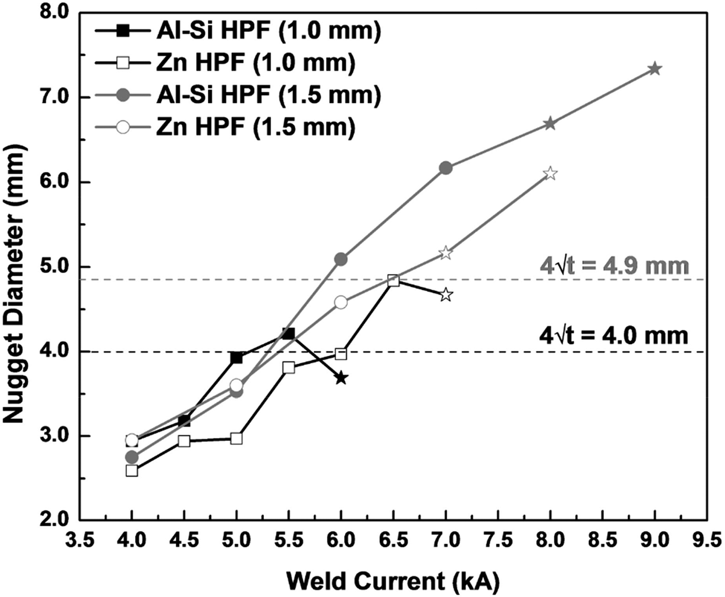
Dynamic resistance (the change in resistance during welding, measured between the electrodes) 25 shown in Fig. 4 was measured between two electrodes during welding of two different steels. The graph indicates higher initial contact resistance 26 and dynamic resistance in the Al–Si HPF, for a specific weld time. The higher contact resistance at the beginning of the weld is believed to be the effect of existing surface oxides in the Al–Si coated sample. It has been reported that the Fe–Al intermetallic phases existing on the Al–Si coating is electrically conductive; therefore, the coating is considered to be compatible to the RSW process. 4 It should be noted here that higher dynamic resistance during welding allows to generate more heat, which eventually enlarges the nugget diameter as corroborated with Figs. 2 3 and 5. Although the other factors such as coating thickness, surface roughness and resistance of the base metal influences the contact resistance during RSW, it was found that these factors have insignificant effect in the hot stamped material, as the resistance of the sheets is about half of the contact resistance between the electrode and sheet. It should be reported that the surface oxides play an important role for increasing the contact resistance; the higher the oxide layer, the larger the contact resistance. 4 Therefore, sometime, it is recommended to optimise the heating cycle of the hot stamping process to minimise the formation of the surface oxides; a slow heating cycle produces thinner oxide layer compared to the fast heating cycle. However, the surface oxides have an adverse effect on spot weldability; therefore, the hot stamped sheets are always followed by either dry ice cleaning or shot blasting process to reduce the contact resistance within acceptable range.
Comparison of dynamic resistance of Al–Si coated HPF and Zn coated HPF at welding current of 6.0 kA
a Al–Si HPF; b Zn HPF
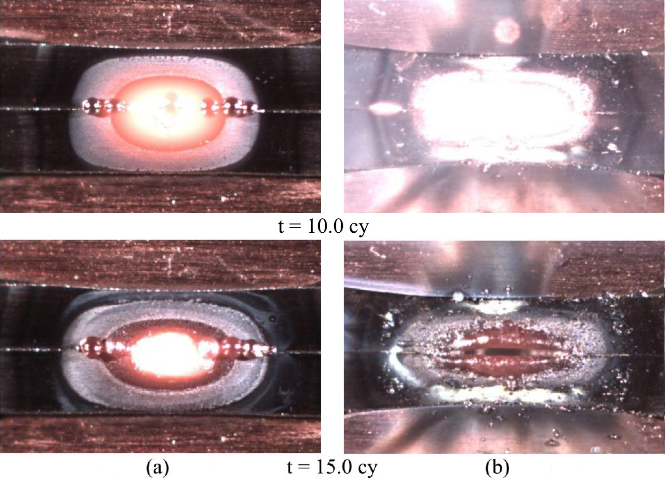
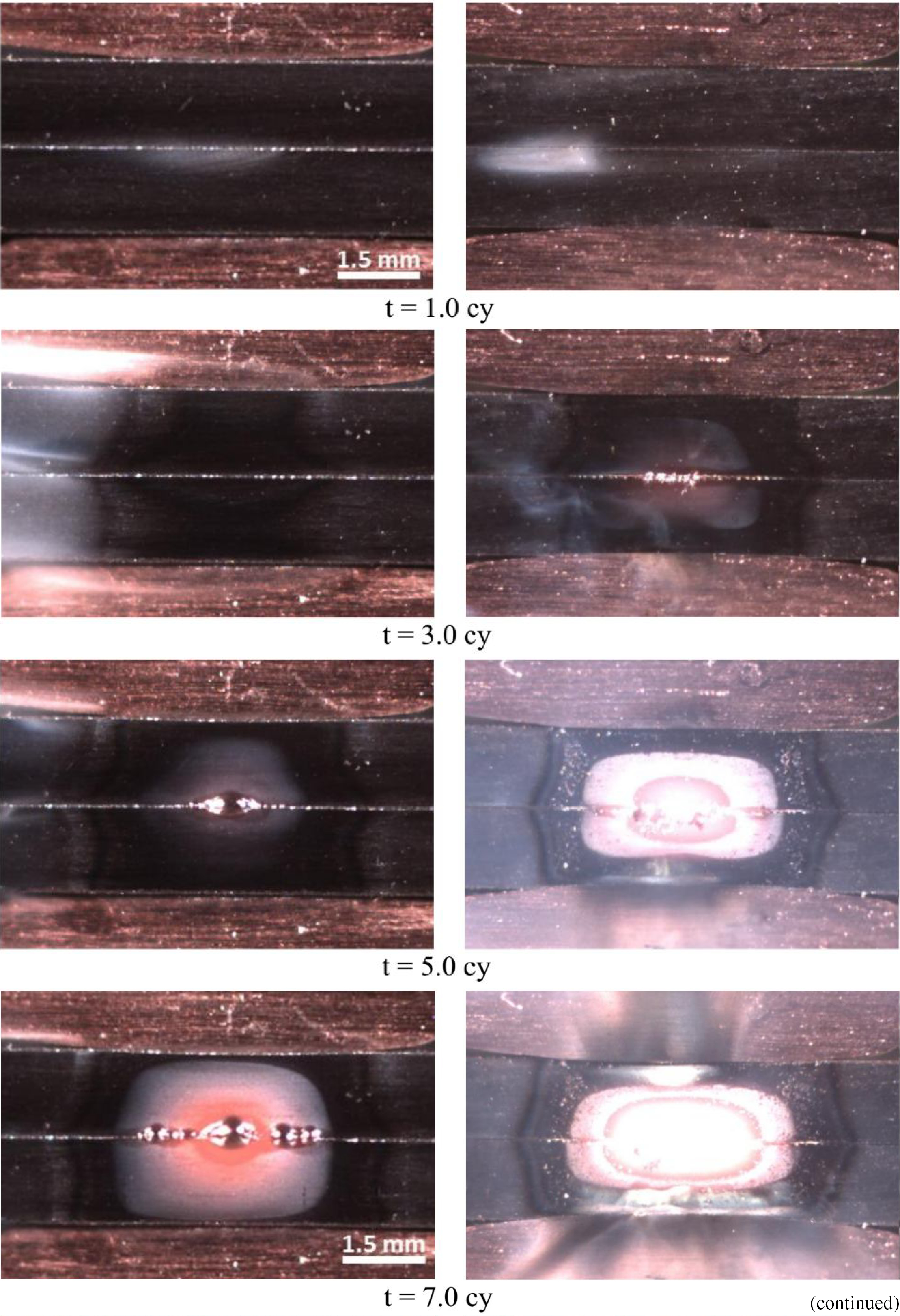
A high speed camera was assisted to visualise the generated heat and the nugget formation mechanism; the captured images are shown in Fig. 5. The coating melting and nugget formation were compared with respect to the welding cycle. At the relatively low welding time (1 cycle), at the start of the weld current, fume generation was observed at F/S, which was due to the presence of impurity and coating layer on the sheets' surface. There were no significant differences; both samples show similar behaviour. At 3 cycles, it was clearly visible that the bulk materials were affected by the weld current and heat propagated from the faying interface to the outward direction. Although bulk materials were heated up, the coating melting in the Al–Si HPF was not detected significantly; conversely, the Zn coating was melted at F/S and simultaneously heat spread outwardly. This implies that the Zn HPF provided additional resistance at F/S and helps to accumulate more heat compared to the Al–Si HPF. At 5 cycles, Al–Si coating melted and liquid formed; afterwards, the molten coating was squeezed out at the F/S as can be visualised in Fig. 5a. Conversely, the earlier nugget formation was found in the Zn HPF (Fig. 5b), at the same weld time, at 5 cycles. This observation (Fig. 5) well agreed with Fig. 3d, where the early nugget formation was also detected in the Zn HPF at 4 cycles. With the further progress of the weld cycle, the controlled nugget formation and uniform coating melting were examined in the Al–Si HPF. In contrast to the Al–Si HPF, inhomogeneous current flow and violent heat generation were detected in the Zn HPF. Non-uniformity of the coating layer and the violent heat generation mainly occurred due to the presence of the oxide on the sheets' surface.4, 27 At the end of the weld, at 15 cycles (end of the applied weld current), a bigger nugget can be found in the Al–Si HPF, which could be the fact of the stable and uniform heat generation/propagation. This phenomenon well agreed with the experimental data presented in Fig. 2, where Al–Si HPF provides a larger nugget diameter. On the other hand, the nugget formation phenomenon is completely different in the Zn HPF, where unstable heat generation can be detected, which was the major reason for getting earlier expulsion as shown in Fig. 2. In addition, a lack of molten liquid in the fusion zone (FZ) was observed in this case (Fig. 5b, at 15 cycles), 27 which suggested that the expulsion may occur in the full weld schedule. Dirty sheet faces and the coating adhesion onto the electrodes were visualised in Fig. 5 (15 cycles); conversely, the clean electrode tip can be identified in the Al–Si HPF.
Effects of coating on heat generation
As previously described, in addition to the F/S interface, the presence of surface coating influences the heat generation at the E/S interface. The combination of these generated heat plays an important role on the final nugget size and shape. As the heat generation pattern was different for both materials, therefore, it is quite important to take into account the thermal distribution across the weldments. Based on the experimental observation, the predicted temperature distributions across the sheets during welding are presented in Fig. 6. Points 1 and 7 represent the temperature of the electrodes inside the cooling water circulating system, points 2 and 6 are the E/S interface temperature, points 3 and 5 are the bulk materials temperature and point 4 is the F/S interface temperature. In Al–Si HPF, it was observed that higher heat was being accumulated at the E/S interface due to the presence of oxides; therefore, the temperature distributions between points 2 and 3, and 5 and 6 were higher compared to the counterpart. This is reasonable as the Al–Si intermetallic phases that exist between the steel substrate and coating layer are electrically less conductive; 26 therefore, Al–Si coated HPF are generally considered to be compatible with RSW process. 4 Another study 9 reported that Al–Si HPF steel provided good spot weldability due to the high melting point of the Fe–Al alloy phase on the surface. The existence of higher heat at the E/S interface allows heat to be soaked into the bulk material and eventually facilitates nugget growth toward the electrode direction. According to the temperature distribution presented in Fig. 6, it can be asserted that the higher heat build-up in the E/S (in Al–Si HPF) will enlarge the electrode tips. At the same time, the higher temperature will allow more coating to be penetrated onto the electrode tip; these issues have been discussed in the section on ‘Effects of electrode contact area on heat generation’.
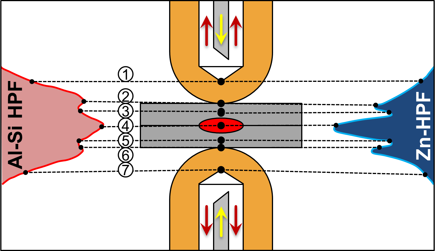
Schematic representation of temperature distribution during resistance spot welding of Al–Si HPF and Zn HPF
Figure 7 shows the coating melting sequences at the F/S interface with respect to the weld current. The welds were performed with varying weld currents from 6.0 to 10.0 kA while keeping other parameters constant (welding time, t = 1 cycle). The melting temperature of the Al–Si coating layer is ∼600°C; 9 therefore, during welding, the coating layer melted quickly and squeezed out from the interface as can be seen in Fig. 7a. The molten coating pushed out intensely to the periphery of the interface, which implies that melting occurred uniformly. Therefore, a high volume of the molten metal can be accumulated and ejected, which made a trace on the sheet surface as can be visualised in Fig. 7a (at 8.0 and 10.0 kA). A close observation showed that in the Al–Si coated HPF, melting initiated at various spots (Fig.7a; at 8.0 kA) rather than at the centre of the F/S; as the weld current increased, the number of spot increased; finally, all spots combined each other. Conversely, in the Zn HPF, heat was concentrated at the centre of the F/S, and molten coating was pushed out slowly towards the periphery of the localised heated area (Fig. 7b).
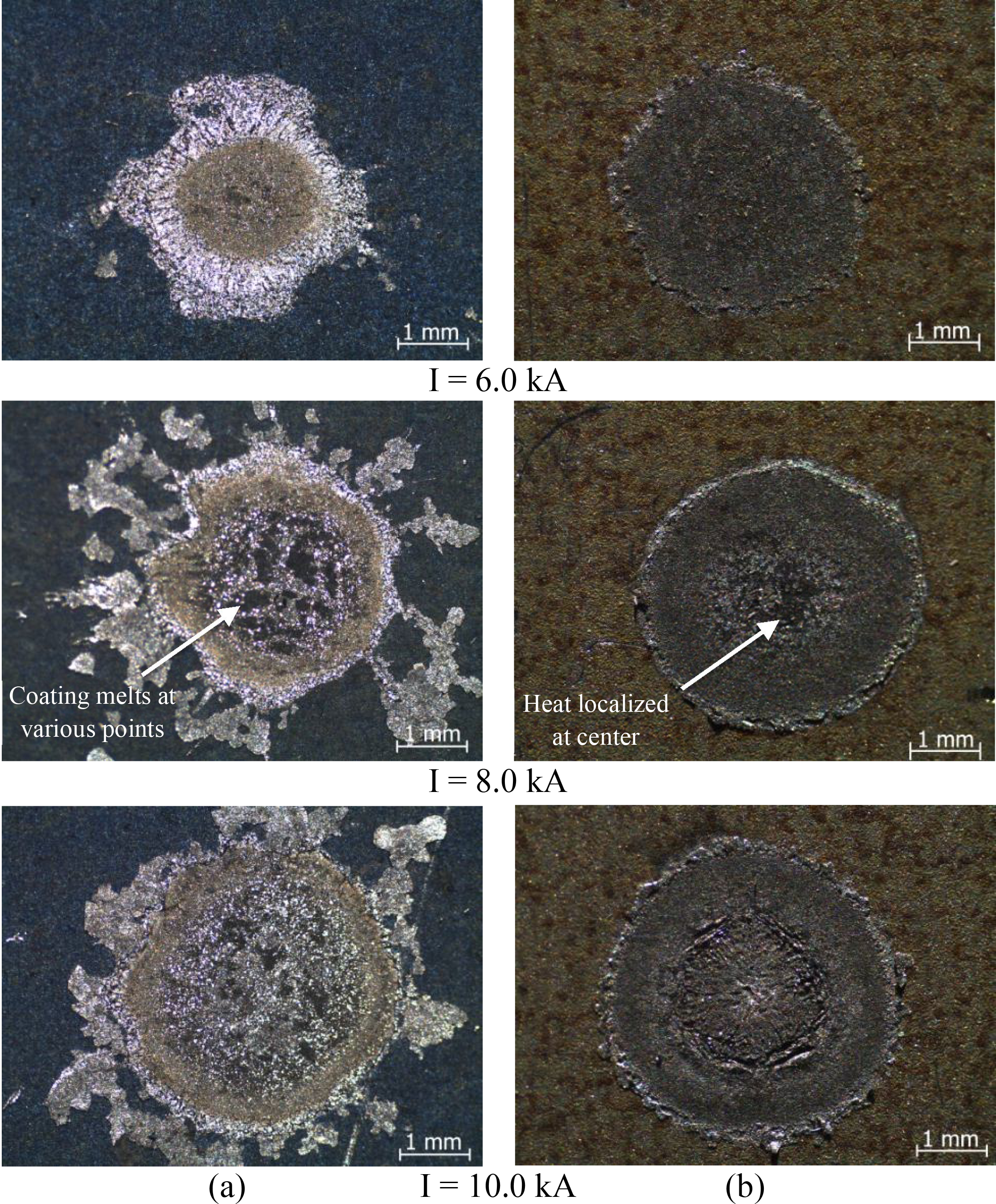
a Al–Si HPF; b Zn HPF
To investigate the element composition distributions at F/S, the samples were welded with a higher weld current (10.0 kA) and a lower weld time (1 cycle), so that complete nugget formation can be avoided. Afterward, element distributions at faying interface were observed using electron probe microanalysis as presented in Fig. 8. The results illustrate a less aluminium concentration circle at the centre of the F/S of the Al–Si coated sample (Fig. 8a). Conversely, iron was exposed at the centre of the F/S, which is a good indication of the removal of the Al–Si layer from the weld centre; in addition, lean oxygen (removal of oxides) concentration annular zone was formed, which offered a stable nugget formation. Another noticeable feature was that silicon was uniformly distributed throughout the periphery of the annular zone. Contrariwise, even though nugget was formed at the centre of the F/S, still a non-uniform zinc distribution can be found in Zn coated sample (Fig. 8b). Rich concentration of oxygen was observed at the periphery of the welded zone, which must be removed before nugget formation; otherwise, it may create a barrier to heat generation and nugget formation. Presence of oxides at the interface suggests inhomogeneous current flow; 28 therefore, an unstable heat generation and propagation can be expected as shown in Fig. 5b.

a Al–Si HPF; b Zn HPF
The coating removal/melting process were further analysed by observing the interface microstructure of the cross-sectioned samples as presented in Fig. 9. Distinguishable coating removal features were detected; coatings were removed from the centre to the F/S and formed uniform intermetallic coating layers (Fe–Al–Si) throughout the F/S interface. In Al–Si HPF, a uniform continuous melted intermetallic layer of ∼8 ± 3 μm (zones ‘b’ and ‘c’ in Fig. 9a) was observed throughout the F/S interface, and the molten coating was pushed from the interface towards the two ends (corona bond area) as indicated by zones ‘a’ and ‘d’ (Fig. 9a). At the initial stage of welding process, the Al–Si coating layer melted and removed easily due to its low melting point 9 and accumulated into the edge of the electrode contact area. The Fe–Al–Si intermetallic phase is electrically conductive; 4 therefore, a uniform coating of this inhibition layer eventually helped to maintain uniform electrical current path.
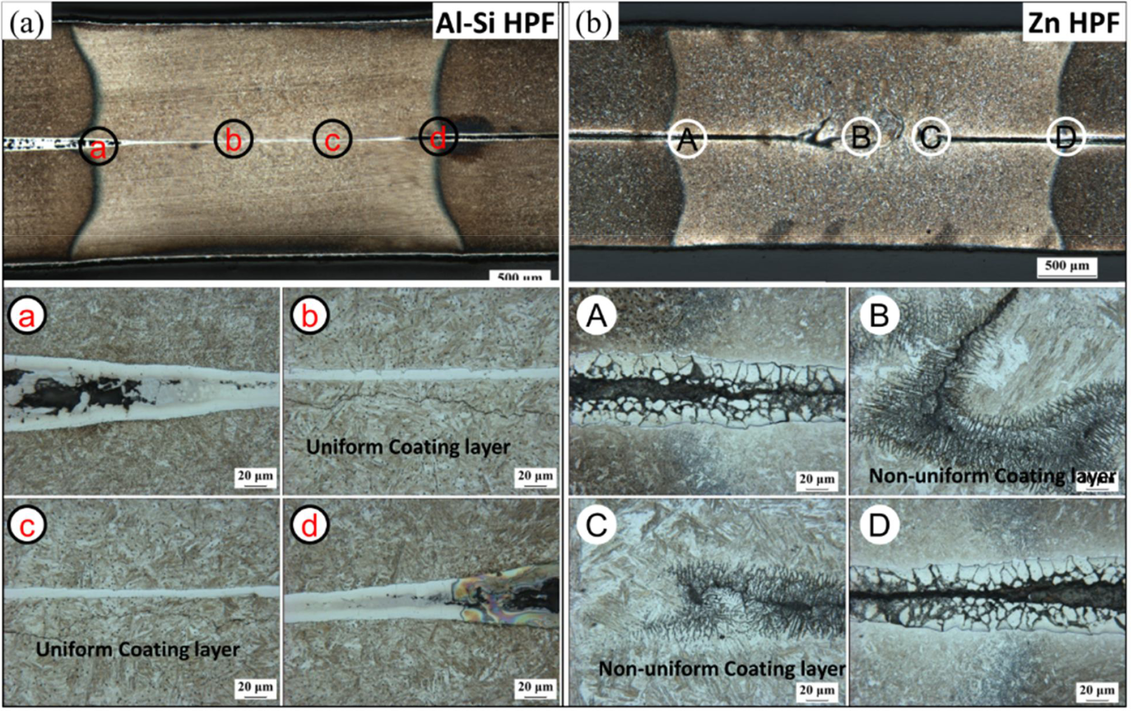
a Al–Si HPF; b Zn HPF
Conversely, in the Zn HPF, the F/S coating layer was not removed uniformly, as can be seen in Fig. 9b. Although nugget was formed in this case, a non-uniformly melted coating can be examined at F/S, as can be seen from zones B and C in Fig. 9b. Most importantly, the Zn–Fe intermetallic layer was not squeezed out as a liquid form, as it was in Al–Si HPF. A high electrical resistivity of the coating layer did not permit sufficient current (as current always passes through the least resistance path) to melt the coating uniformly throughout the F/S rather than to localise heat at the weld centre. Another feature was that the coating layer was not much affected by the electric current at the heat affected zone (HAZ) area (zones A and D in Fig. 9b).
Effects of electrode contact area on heat generation
Electrode indentation onto the surface of the sheets is another important feature that indicates the degree of deformation in the E/S interface under a predefined electrode force. As higher heat was being concentrated at the E/S interface in the Al–Si HPF (Fig. 3a and c), therefore, a higher degree of plastic deformation can be expected. The average penetration/indentation of the electrodes into the sheets was measured to be ∼220 ± 12 μm and 170 ± 15 μm in the Al–Si HPF and Zn HPF (at weld current of 6.0 kA, 1.5 mm sheet) respectively. As a result, more surfaces were brought into contact to the electrode tip, which eventually enlarged the electrode tip surface area as shown in Fig. 10 (contact diameter, 4.15 mm compared to 3.95 mm).
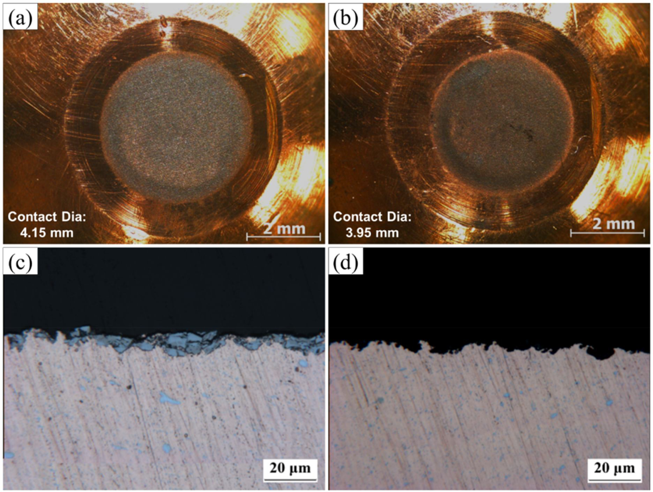
Electrode tips diameter and cross-sectional views for a and c Al–Si HPF (1.0 mm) b and d Zn HPF (1.0 mm) after 20 welds at 3.0 kA weld current
Figure 10 illustrates the electrode contact diameter and the coating penetration into the electrode faces. The experiments were carried out on 1.0 mm thickness steel sheets with a weld current and time of 3.0 kA and 1 cycle respectively. After 20 welds, the electrode contact diameters were measured on a stereomicroscope, and the contact diameters were found to be 4.15 and 3.95 mm in the Al–Si HPF and Zn HPF respectively. It was obvious that a larger electrode contact face would reduce the current density, 29 hence allowing a wide current passing width. Therefore, it will require more time to form nugget initially as detected in Fig. 3. After breakdown of the surface coating, a wider current transient area helps to expand the nugget in all directions as examined metallographically by cross-sectioning the welded part (Fig. 3a for 3 and 4 cycles), and it was further confirmed by examining the nugget growth and heat generation using a high speed video camera, as presented in Fig. 5.
Comparing the effective contact diameter between F/S and E/S among the two different samples, it can be found that the E/S contact areas (Fig. 10) were larger compared to the F/S interface (Fig. 7) in the Al–Si HPF. In addition, this statement can be verified by visualising the heat affected area in the E/S interface (Fig. 3, 1 cycle). In Fig. 1b, a lot of surface cracks were visible in the Zn HPF, and the cracks were extended from the coating surface to the coating/steel substrate interface. These surface cracks might help to concentrate heat in a localised place (weld centre) by quick breakdown. Figure 2 illustrates that, to obtain the same weld size, the Zn HPF requires a higher weld current in identical welding condition. Lesser heat at E/S cannot provide sufficient thermal barrier to help nugget growth in the electrode direction.
Figure 11 indicates the element map of the electrode tip surface for both steels. As it can be seen in Fig. 11a, aluminium, oxygen and silicon were adhered into the electrode tip uniformly. However, aluminium and oxygen showed higher concentration at the centre of the electrode tip. Figure 11b illustrates similar element map in Zn HPF, and it represents a different phenomenon as compared to the Al–Si HPF. In this case, Zn strongly picked up from the sheets onto the centre of the electrode tip, and oxygen, iron and aluminium accumulated at the annular zone around the periphery of the tip. It can be visualised that, although zinc was picked up at the electrode face, it had not formed brass (Zn–Cu) alloy composition, as copper was totally absent where zinc was in rich concentration.

a Al–Si HPF; b Zn HPF
Microstructural observation of weld
Microstructure has changed from as received condition to the FZ depending on the thermal gradient experienced during welding. Five distinct zones can be found in the post-welded weldment, which were categorised as BM, subcritical HAZ (SCHAZ), intercritical HAZ (ICHAZ), upper critical HAZ (UCHAZ) and FZ.30–33 Microstructures obtained in this investigation are presented in Fig. 12; zones in Al–Si HPF are denoted a–e and that in Zn HPF, A–E. The distinguishable features of microstructure were not observed between the used two types of steels, as the microstructure of the as received materials were similar and identical welding conditions were applied. The BM consists of typical lath martensite for both of the materials; however, the prior γ grains were larger in Al–Si HPF, as can be compared from zones ‘a’ and ‘A’ in Fig. 12. The transition zone was formed between BM and HAZ, which referred to the SCHAZ, and it is clearly visible as a black shade in the half section of the weld nugget. In the SCHAZ, microstructure experienced temperature close to the Ac1 temperature line, and the BM martensite structure undergone tempering process or softening (zones b and B).34, 36 During tempering, a virgin martensite microstructure was destroyed, and it was transformed into ferrite and cementite. 34 The tempered martensite usually provides lower mechanical properties compared to the BM; it was reported that the reduction of hardness in this zone has detrimental effect on joint performance.13, 35 The zone next to the SCHAZ is called ICHAZ (zones ‘c’ and ‘C’), where temperature reached between the temperature of Ac1 and Ac3 line, and austenite phase is formed along the prior austenite grain boundary; austenite phase is transformed into new formed martensite and/or bainite 21 upon cooling to room temperature. The zone beside the ICHAZ is the UCHAZ (zones ‘d’ and ‘D’), where temperature is well above the Ac3 temperature line; therefore, complete austenisation occurred. Full austenised microstructure was retransformed into martensite structure due to the high cooling rate involved in the RSW process. However, microstructures are coarser than that of the as received materials (zone ‘a’ and ‘A’), and the final microstructure in the FZ was 100% martensite; directional solidification and typical lath type martensite were observed in this zone (zones e and E).30–33

Microstructural change from base metal to weld metal for a Al–Si HPF, base metal, b SCHAZ, c ICHAZ, d UCHAZ and e FZ and A Zn HPF, base metal, B SCHAZ, C ICHAZ, D UCHAZ and E FZ

Conclusions
In this investigation, the effect of different coating types on nugget formation and heat generation during RSW of hot pressed forming steels is reported. On the basis of experimental results and discussion, the major conclusions can be drawn here.
Coating types of the sheets play an important role in heat generation and nugget formation in RSW of the HPF steels. Al–Si coating helps to grow nugget more uniformly compared to the Zn coating; therefore, nugget diameter was higher in the former case. Although early nugget formed in Zn HPF, the nugget growth rate was rapid in the Al–Si HPF, at the initial stage of welding. In the Al–Si HPF, both faying interface and the bulk resistance are responsible for nugget formation and growth toward the electrode direction. Higher heat was concentrated at E/S interface, which provides larger electrode contact diameter as well as larger nugget sizes for Al–Si HPF. Unlike Zn HPF, for Al–Si HPF, heat generated several points in F/S, and finally, these points merged and formed a larger nugget. Existence of oxide at F/S was the main hindrance to obtain homogeneous current flow and results in violent heat generation in Zn HPF, in contrast to Al–Si HPF, where controlled heat generation was observed.