
Abstract
Currently, the use of advanced high strength steels (AHSSs) is the most cost effective means of reducing vehicle body weight and maintaining structural integrity at the same time. However, AHSSs present a big challenge to the traditional resistance spot welding (RSW) widely applied in automotive industries because the rapid heating and cooling procedures during RSW produce hardened weld microstructures, which lower the ductility and fatigue properties of welded joints and raise the probability of interfacial failure under external loads. Changing process parameters or post-weld heat treatment may reduce the weld brittleness, but those traditional quality control methods also increase energy consumption and prolong cycle time. In recent years, a magnetically assisted RSW (MA-RSW) method was proposed, in which an externally applied magnetic field would interact with the conduction current to produce a Lorentz force that would affect weld nugget formation. This paper is a review of an experimental MA-RSW platform, the mode of the external magnetic field and the mechanism that controls nugget shape, weld microstructures and joint performance. The advantages of the MA-RSW method in improving the weldability of AHSSs are given, a recent application of the MA-RSW process to light metals is described and the outlook for the MA-RSW process is presented.
Keywords
Introduction
In order to greatly reduce a vehicle body's weight and at the same time meet strict occupant safety requirements, advanced high strength steels (AHSSs), which have a high strength/weight ratio and low cost compared with light metals and composites, have been introduced into structural component fabrication to replace the widely used mild steels. 1 However, because AHSSs contain large amounts of carbon and other alloying elements, the local heat input associated with resistance spot welding (RSW) can greatly increase the risk of cracks, element segregation and interfacial failure,2, 3 which reduce the mechanical performance of the welded structure, especially in terms of energy absorption capacity and fatigue life. Post-weld tempering has been used in production to diminish the hardening rate of the weld 4 and thus reduce the risk, but it adds to cycle time and energy consumption. Therefore, with the implementation of AHSSs, the automotive industry has sought alternatives to traditional RSW.
Since the 1960s, it has been known that a magnetic field applied externally to a weld pool interacts with the electric current and generates Lorenz force, which causes non-contact electromagnetic stirring (EMS). The EMS influences heat transfer and fluid flow during the heating stage and breaks dendrites during the cooling stage. In gas tungsten arc welds, the application of an external magnetic field during welding has been found to produce a fine equiaxed grain structure in aluminium alloys and stainless steels.5-7 In 2014, Yang et al. found that an externally applied magnetic field can significantly improve the weld bead quality at high welding speed and thus could enable high speed welding at low cost. 8 However, mild steels, which are dominant in vehicle body structures, have excellent weldability, so EMS has not been introduced to RSW in the automobile industry.
In 1993, Popov first investigated the effect of a radially oriented magnetic field on the RSW of 3.50 mm thick stainless steel and found that the radial magnetic field could eliminate porosities in the fusion zone and improve weld fatigue life. 9 In 2006, Watanabe et al. applied a radial magnetic field of up to 2 T during spot welding of stainless steels and found that EMS could increase the nugget size and thus the weld strength. 10 Since 1996, Li, Wei and their partners have also studied the effect of an induced magnetic field on the RSW process and found that the induced magnetic field could significantly change the flow of molten metal in the weld nugget and thus change the temperature distribution and nugget geometry.11–19 In 2009, Li et al. proposed to install a pair of axisymmetric external magnetic field sources on an RSW gun to realise magnetically assisted RSW (MA-RSW).20, 21 They found that the axisymmetric magnetic field could effectively improve the weldability of AHSSs.22–25 In 2014, Li et al. and Yao et al. applied the same idea to the welding of aluminium and magnesium and found that the MA-RSW process works well in improving the weldability of the light metals, which are generally difficult to weld with the traditional RSW process.26, 27 Although study has been extensive and progress has been made in recent years on magnetic assisted welding, the work in RSW is still very limited.
In this paper, the development and advances in MA-RSW are reviewed in light of the challenges that arise when RSW is used to weld AHSSs. The MA-RSW experimental set-up, the role of the external magnetic field and its effects on weld geometry, microstructure and performance will be reviewed to assess the ability of the MA-RSW process to improve the weldability of AHSSs. The recent application of the MA-RSW process to light metals is reviewed, too. The outlook for the MA-RSW process is also discussed.
Magnetically assisted RSW excitation system design
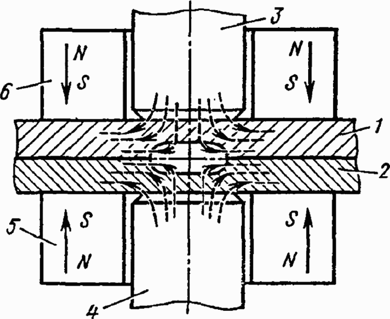
During the RSW process, when the welding current flows through a workpiece, a magnetic field normal to the symmetric plane of the electrodes is induced (Fig. 1). Based on the electromagnetic theories, the electric current density and the induced magnetic field will interact with each other to produce a Lorentz force in the symmetric plane, and the induced magnetic force will drive the molten metal in the nugget to flow in the symmetric plane. 22
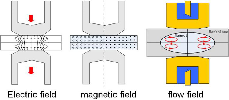
Electromagnetic fields and possible flow pattern in traditional resistance spot welding22
To enhance the flow in the molten nugget, an external magnetic field should produce a magnetic force field that is orthogonal with the induced magnetic force field so that there is no interference between them. 22 Thus, as shown in Fig. 2a, a magnetic force field that is perpendicular to the symmetric plane, with one side in and the other side out, should be selected so that there is no any interference between the induced magnetic force field and the external magnetic force field. This kind of arrangement requires an axisymmetric magnetic field, shown in Fig. 2b, which can only be produced by a pair of cylindrical magnets or excitation coils, as shown in Fig. 2c. A single magnet or excitation coil would also work well if welds that are non-symmetrical with respect to the faying surface are acceptable.
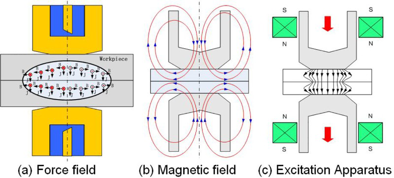
a force field; b magnetic field; c excitation apparatus
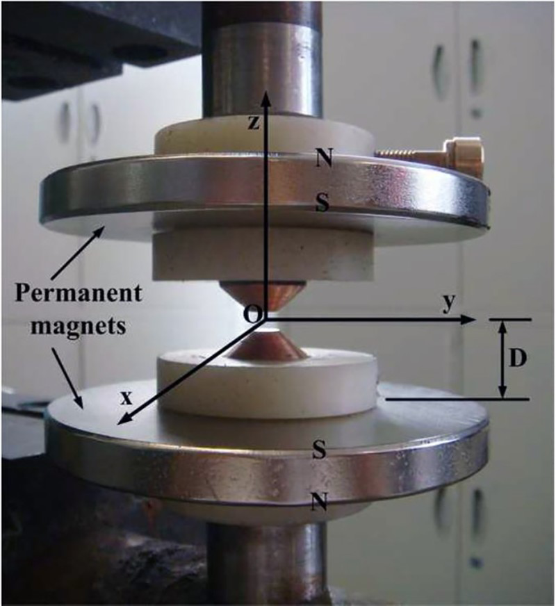
Li et al. and Shen et al.22–25 used a pair of ring shaped NdFeB permanent magnets as the external magnetic sources to produce an axisymmetric magnetic field (Fig. 3). The two magnets were installed symmetrically along the electrodes with their north poles (marked ‘N’ in Fig. 3) against each other. The distance between the two magnets was greater than the total thickness of the sheets so that there was a gap between the magnets and the adjacent sheets. The magnets were 20 mm high; their inner and outer diameters were 20 and 40 mm respectively. The remnant magnetism (Br) of the permanent magnet was 1.22 to 1.25 T, the maximum magnetic energy product (BH) was 287–310 kJ m− 3 and its intrinsic coercive field (HcB) was ∼907 kA m− 1. An FANUC robotics R2000-Ib210f system with six degrees of freedom, integrated with a Medar 5000s medium frequency direct current welding controller and an Obara C type servo gun was used as a basic platform for the MA-RSW experimental investigations. Li et al. and Yao et al. used the same design on their medium frequency direct current welder, but the magnets were larger in diameter and thinner,26, 27 as shown in the photograph on the right in Fig. 4.
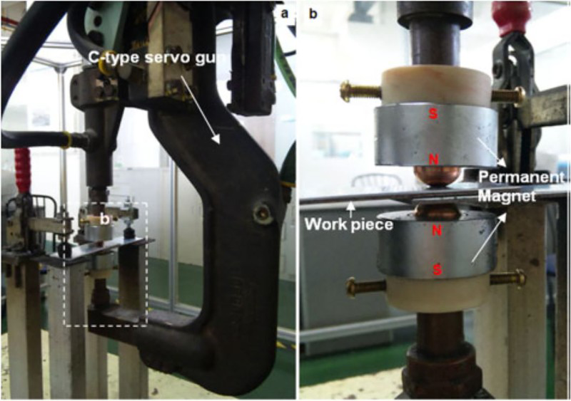
Magnetically assisted resistance spot welding experimental apparatus used by Li et al.26
Popov 9 used a pair of cylindrical permanent magnets on an ac welder. As shown in Fig. 5, the two magnets were directly attached to the sheet surfaces to eliminate magnetic leakage. Watanabe et al. 10 indicated that they tested two magnetic fields on an ac welder. As shown in Fig. 6, the field is perpendicular to the welding direction; the other is parallel to the welding direction. Watanabe et al. did not present any further information about the external magnetic field source.
Magnetically assisted resistance spot welding experimental apparatus used by Popov9
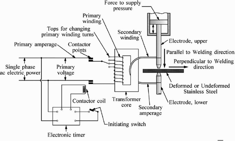
Magnetically assisted resistance spot welding experimental apparatus used by Watanabe et al.10
Liquid nugget formation mechanism in MA-RSW
In theory, there are two kinds of orthogonal magnetic force fields in the MA-RSW process. One lies in the symmetric plane and produces an in-plane fluid flow. The other is perpendicular to the symmetric plane and thus produces an out of plane flow in a circumferential direction. Obviously, the two types of fluid flow would interact with each other and cause a complicated flow pattern in the transient nugget. Because of the invisibility of the weld nugget formation, it is very difficult to directly observe the fluid flow and heat transfer behaviours in the nugget formation. Cunningham and Begeman 28 and Alcini 29 conducted indirect experimental tests in the last century; however, numerical methods have been the main means to understanding the fluid flow and temperature evolution in the RSW process. Because of the significant increase in complexity caused by the introduction of an external magnetic field, all the current studies of the mechanism of weld nugget formation only consider the effect of the induced magnetic field inside the nugget.
Numerical study on nugget formation
Numerical modelling methods could avoid the limitations of the experimental means and can be used to flexibly and effectively analyse on the multiphysics behaviours in RSW.30-34 The experimental studies by Alcini revealed that the induced EMS in RSW could produce a uniform liquid nugget. However, because of the complexity and severe non-linearity of the multiphysics coupling in RSW, it was assumed for many RSW numerical models that there is flow of molten metal in the weld nugget and that a large temperature gradient exists throughout the RSW process. Since 1990, some researchers have used the finite difference (FD) method and the finite element method to investigate the fluid flow behaviours in the nugget.
Finite difference modelling and simulation
Wei et al. 11 pioneered the modelling of flow and heat transfer behaviours in the liquid weld nugget using a two-dimensional (2D) FD model early in 1996. The unsteady transport phenomena during RSW for different values of the parameter governing current, dimensionless electric contact resistance, face radius and cone angle of the electrode, workpiece thickness, magnetic Prandtl number and solid/liquid electrical conductivity ratio were presented in detail for the first time. He found that two cells in the first quadrant of workpieces occur for the truncated cone electrode. The right and left cells are in the counterclockwise and clockwise directions respectively, as shown in Fig. 7a. The only cell induced by the flat face electrode is in the counterclockwise direction (Fig. 7b). The calculated maximum velocity in the molten nugget can be as high as 0.3 m s− 1.
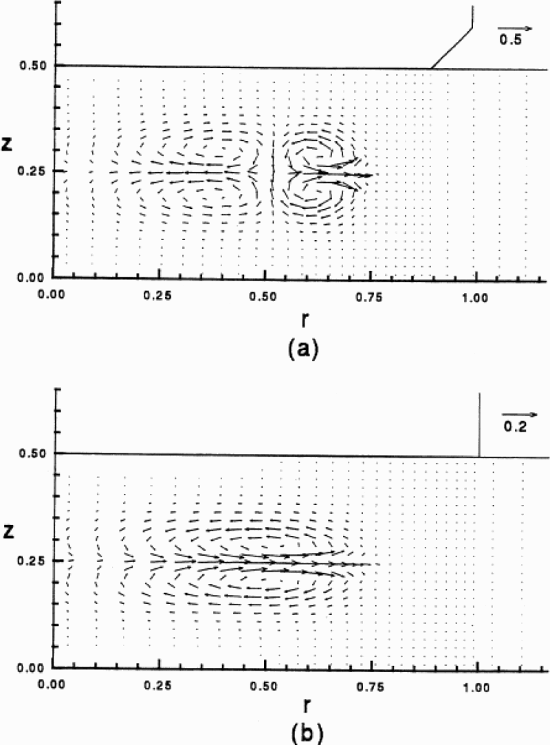
a truncated electrode; b flat electrode
Since 2010, Professor Wei has made significant contributions to the understanding of RSW nugget formation mechanism by undertaking a more systematic study of the transport behaviours in RSW under an induced magnetic field. He has considered the effect of electric welding type, 17 magnetic property effect, 18 phase change, 19 electrode contact condition, 35 electrode geometry,36, 37 electrical contact resistance 38 and workpiece properties. 39
In 2000, Khan et al. and Khan and Broach40, 41 built a three-dimensional (3D) FD model to study the natural convection inside the weld nugget caused by density and thermal gradients. He found that the maximum fluid flow caused by gravity is only 0.01 mm s− 1 and indicated that a model including the Lorentz force should be developed to study the enhanced flow inside the weld nugget.
Finite element modelling and simulation
To simplify the problems in the MA-RSW process, Li et al.12-16 assumed that molten metal in a closed nugget was a Newtonian, incompressible and viscous fluid, the effect of gravity was ignored and the magnetic field was assumed to be quasi-stable. Based on these assumptions, Li et al. gave detailed Magnetohydrodynamics (MHD) equations consisting of the continuity equation, the momentum equation, the energy equation and Maxwell equations, and taking into account the macroelectromagnetic characteristics of media in electromagnetic field. For numerical stability calculations, a modified effective viscosity model was used to model the mass transport in the mushy zone with no need to manually locate the liquidus and solidus temperature in iterations. With this method, a high viscosity was assigned to the solid phase to make sure that the solid region would not move under the magnetic force. Meanwhile, real viscosity values were assigned to the liquid phase to make sure that the molten metal could flow normally.
Because the induced magnetic force produces a flow in the symmetric planes, the electric, thermal and fluid flow fields are all axisymmetric with regard to the axisymmetric axis of the electrodes. Thus, they can be described using an axisymmetric model. The induced magnetic field in RSW is physically normal to the symmetric plane as shown in Fig. 1. Therefore, the magnetic field cannot be modelled with an axisymmetric model. In view of the above symmetry features of MA-RSW, Li et al. used a one-half 2D axisymmetric model for electrothermal analysis, a one-fourth 2D axisymmetric model for fluid dynamics analysis and a one-fourth 3D wedge shaped model for magnetic analysis, as shown in Fig. 8.
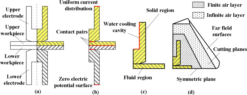
a schematic view of RSW process; b one-half 2D electric model; c one-fourth 2D flow model; d one-fourth 3D magnetic model
As shown in Fig. 5b, the welding current was assumed to flow uniformly through the upper surface of the top electrode, and the lower surface of the bottom electrode was defined as the reference zero potential surface. Because the induced magnetic field is perpendicular to the symmetric planes, the magnetic vector potential Aθ equals 0 on the two symmetry cutting planes in the circumferential direction. On the external surface of the far field air layer, the magnetic field attenuates to zero (i.e. Ax = Aθ = Ay = 0), as shown in Fig. 5d. For fluid flow analysis based on a modified effective viscosity method, the whole sheet was assumed to be a fluid, and the real liquid/solid interface was automatically located through calculated temperatures, as shown in Fig. 5c. Because the duration of the RSW process is very short, heat loss by radiation was ignored. Natural convection was assumed for heat exchanges between workpieces and electrodes and the surrounding air. Because the flow velocity of cooling water driven by a pump is very high, the wall temperature of the cooling cavity was assumed to be equal to the water temperature.
The entire multiphysics analysis was conducted with an incremental method. In each time step, the 2D electrothermal analysis was performed first to output current density and time integrated Joule heat, and then, the 3D magnetic analysis was carried out with the current density from the electrothermal analysis as input to calculate the time averaged magnetic force field. The fluid dynamics analysis was carried out with the Joule heat and the magnetic force field as inputs. ANSYS/multiphysics was used to conduct the multiphysics and multidimensional analyses. The material models are listed in Refs. 12–14.
Induced magnetic force field in weld nugget
As shown in Fig. 1, the induced magnetic force in MA-RSW is axisymmetric, and the magnetic force for the upper half domain of the one-half axisymmetric model is symmetrical with the lower half. 18 Therefore, only the magnetic force analysis results for the top right quadrant of the workpiece are plotted (Fig. 9). The magnetic force field points to the leftmost symmetrical axis as a whole, although its acting direction is not entirely consistent from the edge to the centre (Fig. 9). This might be the reason that Cunningham and Begeman 28 and Alnici 29 defined a flow hypothesis shown in Fig. 11. Within the weld nugget, the magnetic force diminishes from the brim of the nugget to the symmetrical axis in the width direction. In the thickness direction, the magnetic force along the path shown in Fig. 6 increases quickly and produces a large magnetic force gradient in the nugget. As the nugget grows, more magnetic force will be applied to it.
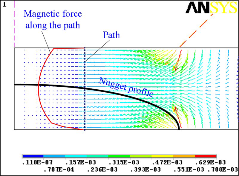
Magnetic force at first time step; unit is N m− 3 (Ref. 15)
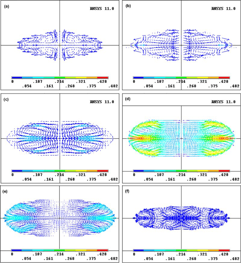
a 0.2465 s; b 0.2515 s; c 0.262 s; d 0.350 s; e 0.364 s; f 0.432 s
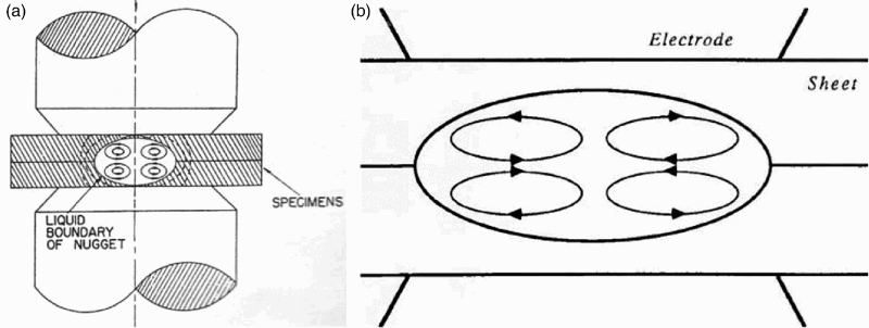
Molten metal flow pattern in resistance spot welding by a Cunningham and Begeman28 and b Alcini29
Flow field evolution by induced magnetic field
During RSW, whether the molten metal exists or not, as long as there is current flow in the nugget, the magnetic force field exists inside the nugget. Thus, once the molten metal appears, EMS will take effect and drive it to flow.
Li et al. started to investigate the flow of molten metal in weld nugget since 2005 and found that, at initial time, the molten metal flows toward the nugget centre along the faying surface and then flows out along the thickness direction to form a loop in each quadrant as shown in Fig. 10a. This is identical to the hypotheses of Cunningham and Begeman 28 and Alcini 29 (shown in Fig. 11). When the nugget gets bigger, however, the flow pattern is reversed and develops more flow cells, as shown in Fig. 10b. With continuous growth of the nugget, the flow pattern in the nugget is completely reversed and remains until the end of the welding phase, as shown in Fig. 10c and d. Moreover, because the nugget is much wider than it is thick and because the liquid metal keeps flowing out of the nugget along the faying surface, the rotation centre in each quadrant gradually moves away from the nugget centre, as shown in Fig. 10a–d.
The change of flow pattern in the midst of nugget formation can be explained with the non-uniform magnetic force distribution shown in Fig. 6. The liquid metal flows into the nugget centre and then flows out along the axisymmetric axis when the nugget is small because the melting initiates at the faying surface and the magnetic force consistently points to the nugget centre. With the growth of the nugget, a larger magnetic force acts on it. Moreover, the magnetic force field over the faying surface deviates gradually toward the thickness direction, which conflicts with and tends to inhibit and reverse the existing flow pattern and thus produces more flow cells in each quadrant of the nugget. As the nugget grows, its area of resistivity increases, which causes the current density field to shift a little outward and to produce a larger deviation in the acting direction of the magnetic force field. Under the action of these factors, a counterclockwise flow pattern forms that is completely different from those hypothesised by Cunningham and Alcini (see Fig. 10d ).
When the welding process enters into a holding phase, the magnetic force disappears, but inertia causes the flow to continue in the flown field. However, the viscosity of the molten metal falls quickly because of fast heat dissipation into the cooling water in the thickness direction. Therefore, the flow field slows down dramatically. More rotation cells are formed because the nugget is still large in the width direction, and strong mass transport mainly occurs near the nugget edge. This flow pattern maintains until the holding phase is finished, as shown in Figs. 10e and f.
The molten metal makes a centrifugal motion in the circumferential direction under the action of the external magnetic field, as shown in Fig. 2a. In theory, the centrifugal motion would produce a high pressure gradient at the edge of the nugget and would cause the molten metal there to move toward the thickness direction. That kind of flow would be consistent with the flow caused by the induced magnetic force and thus would enhance the in-plane flow further and would improve the EMS effect in the nugget.
Effect of fluid flow on heat transfer in weld nugget
The flow of the molten metal affects the heat transfer behaviour in the nugget. Li et al.14, 15 found that the traditional model cannot consider the fluid flow; thus, the calculated temperature gradient in the nugget consists of a series of concentric ellipses and is especially larger in the thickness direction because of the forced water cooling (Fig. 12a). However, for the model that considers the induced magnetic field, the strong flow in the nugget substantially disturbs the regular thermal conduction pattern and mixes the hot and cold metal through non-contact EMS, which greatly reduces the temperature gradient and maximum temperature in the nugget (Fig. 12b).
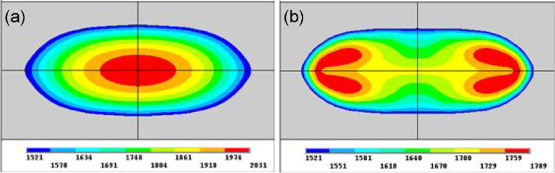
Calculated temperature field in the nugget with a traditional electrothermal model and b MHD model; unit is degrees celsius13,14
The difference in the final temperature field of the two models originates from different transient temperature evolution throughout the welding process. As shown in Fig. 13, Li et al. 16 found no difference between the two models before melting occurs because the magnetic force cannot move the solid metals. However, for the case that does not consider EMS, the temperatures rise sharply and linearly after the phase transformation stage until the welding current is switched off (Fig. 13b). The nugget centre (P1) reached 2118°C, which is the highest in the five locations. That temperature is very different from Alcini's measurement, 29 which is shown in Fig. 14. However, for the model that considers EMS, for all the five locations shown in Fig. 13a, the temperature rise lasts only for a little while and then is maintained at a constant value until the welding phase is completed. Moreover, the stagnation temperature on the faying surface increases with the distance from the nugget centre. P4 is within the rotation centre, and the effect of the fluid flow on it is relatively weak. Thus, its temperature increases a little until 1806°C, and it becomes the highest of the five locations. The temperature evolution agrees well with Alcini's measurement, given the EMS effect.
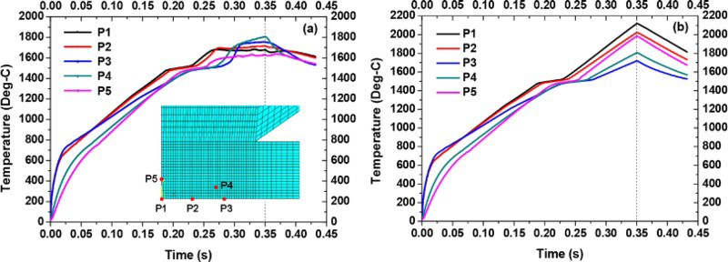
a with induced electromagnetic stirring (EMS) considered; b without EMS being considered
Weld temperatures as function of time29
By comparing the two models, it can be observed that the cooling rate in the holding stage is greatly reduced under the action of the induced magnetic field. However, this is only the effect of the induced magnetic field. The flow in the nugget is enhanced, and the temperature field should be more homogeneous when the external magnetic field is applied, and thus, the reduction in the cooling rate will be further improved. As a result, the MA-RSW process has the potential to reduce weld hardening in AHSS spot welds.
Experimental observation on nugget formation
In 1965, Cunningham and Begeman, at The University of Texas at Austin, 28 photographed a projection welding process on one-half of a weld (Fig. 15). High speed photographs (up to 8000 frames/s) were taken with a Fairchild high speed camera during welding. From the photographs, it is possible to observe all aspects of the weld, such as the character and magnitude of the EMS in the molten weld metal and the temperature distribution through and around the weld. However, due to external lighting effects and progressive changes in the oxide colouring, no accurate temperature determination could be made. The authors thought that the entire molten nugget was of a nearly uniform temperature. The temperature varied with time; the variation was caused by violent EMS. They found that the motions on the two sides of the nugget were in opposite directions; estimates of the stirring velocities reached 0.5 to ∼1 fps at the peak of current pulses. The motion in the nugget interior was later revealed to be higher, but it was impossible to measure the velocities at that point.
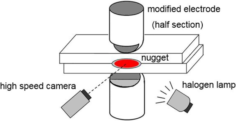
High speed photography set-up for observing spot weld nugget formation in 0.062 in thick SAE 1008 (Cunningham and Begeman)28 (process parameters: 5800 A current and 170 lb force)
Based on the initial motion that they found, Cunningham and Begeman made an analysis of the ideal fluid motion in the nugget. They thought that the relative directions of current and magnetic fields result in a force directed toward the central axis and perpendicular to current paths, while the magnetic force field decreased above and below the interface because the current diverged. Thus, they concluded that the maximum force causes liquid to be pushed along the interface toward the axis, where it tends to flow either up or down and then out along the outer boundary of the nugget, as shown in Fig. 16a.
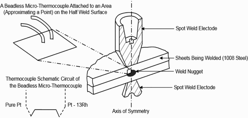
Beadless microthermocouple instrumentation of half weld29
In 2003, Cho and Rhee, of Hanyang University in Korea, 42 used the same digital high speed photography method to examine the nugget formation mechanism in RSW and its relation to the process parameters (i.e. the same half section truncated dome type electrode and illumination system, images acquired at 1000 frames/s and a resolution of 256 × 240 pixels). The results were compared to the changes in dynamic resistance. Heat generation occurring in the primary stages of welding was observed as the shape of the darkening phenomenon on the front face of the welded zone. However, the authors did not present the temperature or the fluid flow within the nugget in the paper.
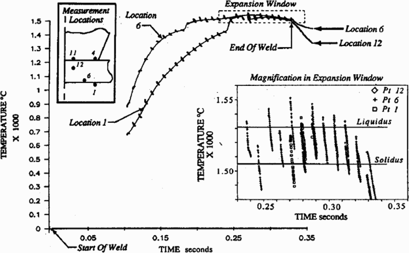
In 1990, Alcini 29 measured the transient temperature during RSW with a beadless microthermocouple sensor, which was made by joining very fine thermocouple wires (0.025 mm diameter) ultrasonically or percussively to the surface of interest (see Fig. 16). The beadless microthermocouple sensor was attached to the sectioned surface of a spot weld. Two 1.5 mm thick 1008 steel sheets were welded together by class II copper A pointed nose electrodes with a face diameter of 6.35 mm. The ac welder was set to 10 000 peak amps and 1.3 kN force. The materials were welded in a ‘half weld’ condition. (A half weld is spot weld sectioned along the line of symmetry.) The welded sheets and electrodes were both sectioned. The sectioned surface was sealed with a refractory cement to retain the liquid nugget, eliminate heat radiation loss and control deformation of the sheets.
Alcini found that the temperature in the weld was essentially uniform and did not climb up at the high temperature stage, as shown in Fig. 14. 29 A uniform temperature is novel to the present theories about the amount of convection taking place in the liquid nugget. If no stirring of the liquid nugget were taking place, the gradient of temperature in the liquid should be greater than that in the solid. Alcini explained that the magnetic forces on the current conducting liquid establish a flow pattern in the molten nugget and that the magnetic field is generated by the large time varying welding current. Given the direction of current flow and the geometry of a conventional weld in ac resistance welding, Alcini described a hypothetical liquid nugget flow pattern (Fig. 8b) that was the same as that described by Cunningham and Begeman.
The above experimental measurements of liquid nuggets in RSW indicated that a violent convection took place that resulted in a uniform liquid nugget. It was believed that an external magnetic field would further enhance the convection in the nugget and thus would further homogenise the temperature in the liquid nugget. However, because of the circumferential centrifugal flow in the nugget, the high speed photography method cannot be used to observe the liquid nugget formation.
Weld characteristics and performance of MA-RSWs
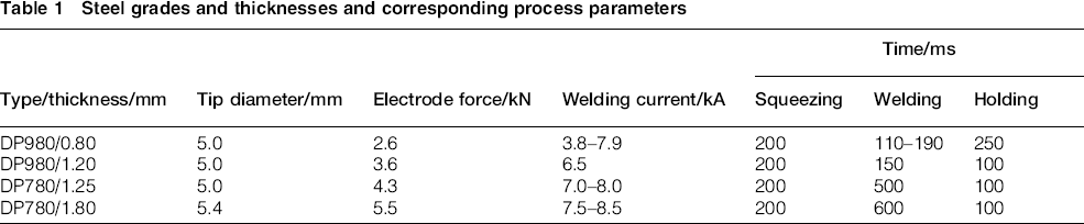
To validate the effect of MA-RSW in improving weldability of AHSSs, Li et al. and Shen et al. studied two thicknesses of the most popular high strength steels (DP780 and DP980).22–25 The process parameters used for each steel grade and thickness are listed in Table 1. To get the best effect, two different kinds of magnetic orientation were compared. One used a single permanent magnet, and the other used two symmetrical permanent magnets.
Steel grades and thicknesses and corresponding process parameters
Effect of external EMS mode on nugget shape, grain size and microstructure
Figure 17 shows the microstructure of the welds made with 0.8 mm thick DP980 sheets. 22 Compared with the traditional welds, the nugget diameters obtained under a single magnet and a pair of permanent magnets were increased by 9.7 and 11.6% respectively. In addition, the two types of MA-RSW nuggets were dog bone shaped (i.e. the edges were thicker than the middles) (Fig. 17b and c), in contrast with the ellipsoidal nugget of the traditional weld (Fig. 17a).
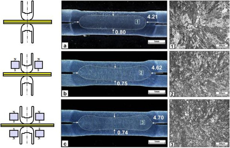
a traditional weld; b MA-RSW using single permanent magnet; c MA-RSW using pair of permanent magnets
The differences in nugget shape can be explained by the effect of the Lorentz force on the flow mode of the molten metal. In the MA-RSW process, the molten metal will flow both radially in symmetric plane because of the induced magnetic field and circumferentially because of the external magnetic field. As a result of the centrifugal flow, more heat will be brought from the centre of the nugget to its edge, and thus, the thickness of the nugget is decreased in the middle portion but the width of the nugget is increased. The stirring effect near the edge of the faying surface is much stronger than that at the centre of the nugget, so a large pressure gradient forms around the edge along the width direction. Because the molten metal is constrained by the surrounding unmelted solid metal, it moves upward and downward, and thus, the nugget will thicken around the edge area and result in the dog bone shape shown in Fig. 17c. However, the nugget under a single permanent magnet is not symmetrical along the faying surface because of the weak magnetic field on the bottom sheet. Such nugget offset is usually not preferred when welding two sheets with equal thickness. However, it might be a way to improve the nugget offset in welding stacks of multiple sheets of different thicknesses.
Differences in MA modes not only change the nugget shape but also affect the microstructures within the nugget. As shown in Fig. 17, the macrosolidification directions in the two MA-RSW nuggets are both less obvious compared with that of the traditional weld. Moreover, under a pair of permanent magnets, the oriented growth of the dendrites is less directional, and the faying surface is less visible. Therefore, compared with the MA-RSW under a single magnet, the weld under a pair of magnets exhibits better quality in terms of nugget symmetry, nugget diameter and nugget microstructures.
The tests conducted using a pair of permanent magnets is reviewed in the following sections.
Effect of EMS on weld static performance and failure mode
Shen et al. 24 conducted quasi-static strength tests on the traditional RSW and on MA-RSW welds of 1.25 mm thick DP780 at 7.8 kA welding current under tensile shear and cross-tension loads. A KQL-WDW100 electronic universal testing machine was used to evaluate the quasi-static properties of the welds.
The typical load–displacement curves under tensile shear testing are presented in Fig. 18. Failure modes of the two types of welds were both button pullout fracture. The MA-RSW welds performed better than the traditional welds in terms of failure load and displacement at the failure. The tensile shear force of the MA-RSW weld was 17.7 kN, ∼12.0% higher than that of the traditional welds. The corresponding total displacement at the failure point of the EMS-RSW welds was 3.93 mm, ∼15.9% longer than that of the traditional welds. Results of the cross-tension testing were consistent with those of the tensile shear testing, as shown in Fig. 18. Failure modes of the two types of welds were both button pullout fracture. The cross-tension force and the corresponding total displacement at failure of the MA-RSW welds were respectively 27.4% higher and 8.7% longer than those of the traditional welds. The results suggest that the MA-RSW method could improve weld strength and enhance weld ductility, which could be explained exactly by the wider weld nugget and the refined grains in the MA-RSW process.
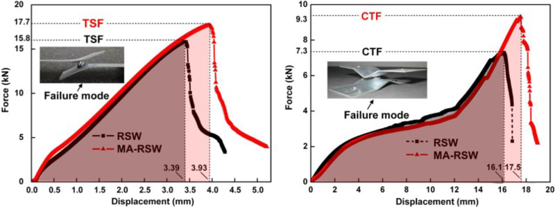
Typical tensile shear/cross-tension load versus displacement curves for welds of traditional RSW and MA-RSW of 1.25 mm DP780 at 7.8 kA welding current24
Li et al. carried out further experiments with 0.8 mm thick DP980 to examine the effect of MA-RSW on weld strength and failure mode. 22 Table 2 shows that the tensile shear strength of the MA welds was stronger and that the displacement at fracture was longer than those of the traditional RSW welds. The improvement of weld strength and ductility became less obvious with the increase in welding current. With less heat input under relatively low welding current, the small weld that formed had a high risk of interfacial fracture under tensile shear loads. Thus, the increase in nugget diameter and the refinement of microstructures would lead to the relatively obvious improvement of weld strength and ductility. In contrast, with more heat input under relatively high welding current, a big weld was formed, and it had a high probability of button pullout fracture. In that circumstance, failure loads and elongations depended on weld quality and on the property of the base metal. Thus, the improvement of weld mechanical performance due to nugget diameter increased, and the refinement in the microstructures was less obvious.
Comparison of mechanical performance of traditional welds and magnetically assisted welds along with variation of welding current (welding time, 150 ms; WD, 3 mm) 22
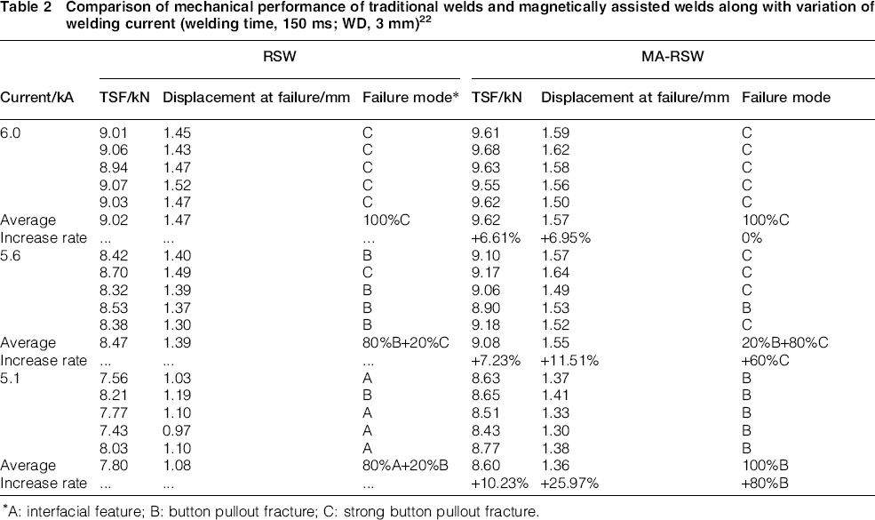
A: interfacial feature; B: button pullout fracture; C: strong button pullout fracture.
Effect of external EMS on macrostructures and microstructures of fracture surfaces
Li et al. used weld fractographs of 1.8 mm thick DP780 sheets at 7.5 kA and 8.0 kA for both RSW and MA-RSW to further reveal the effect of EMS on weld performance. 23 As shown in Fig. 19, for welds made with traditional RSW, an extensive shrinkage cavity was found in the weld at 7.5 kA, and small shrinkage cavities were found for 8.0 kA welds. However, in the welds made with MA-RSW, the sizes of the shrinkage cavities were much smaller than those in the normal welds. The dendritic structures shown in Fig. 20 further indicate that the cavities resulted from solidification shrinkages.
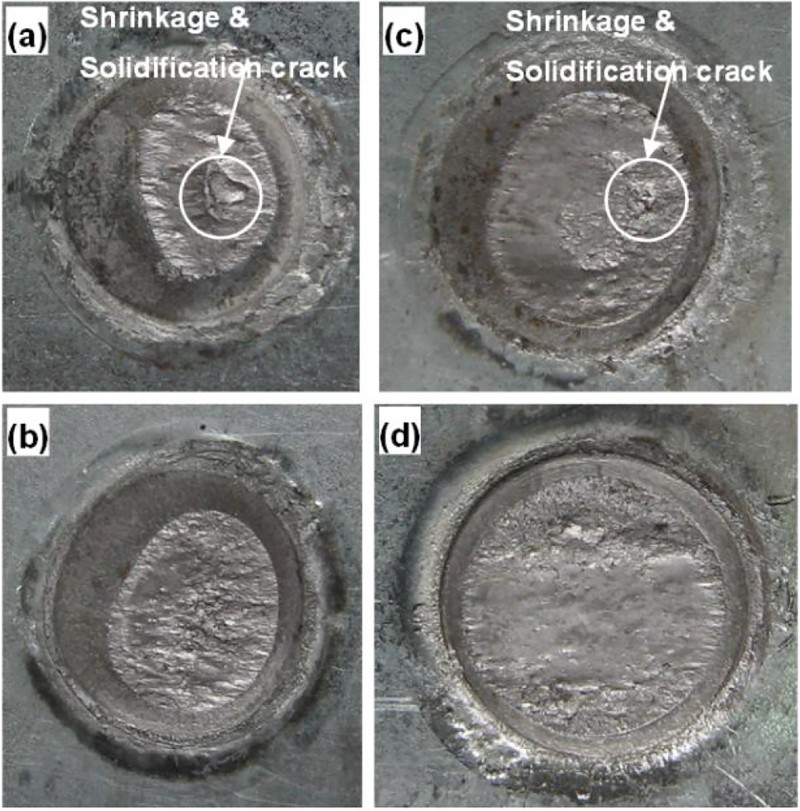
a 7.5 kA with RSW; b 7.5 kA with MA-RSW; c 8.0 kA with RSW; d 8.0 kA with MA-RSW
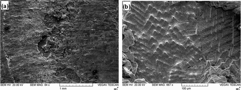
a small shrinkage cavities; b dendrite structures in cavity
As relatively higher tensile shear strength increase was obtained at 8.0 kA with MA-RSW, the tensile shear test fracture surfaces at 8.0 kA were further investigated with higher magnification at the plastic shear zone of the fracture faces. For the conventional weld, as shown in Fig. 21a, both small dimples and large quasi-cleavage fracture were found in the microfractograph. However, for the weld made with MA-RSW, as shown in Fig. 21b, only dimples were found in the fracture. Moreover, the dimples were significantly stretched, which indicates that large plastic deformation occurred before fracture.
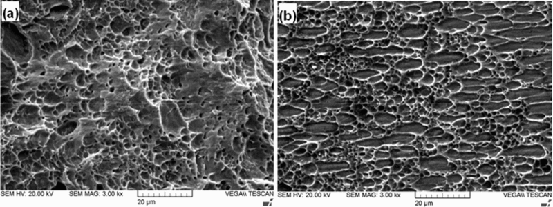
a without RSW; b with MA-RSW (welding current: 8.0 kA)23
Effect of external EMS on fatigue performance
Shen et al. carried out fatigue life testing on 1.25 mm thick DP780 steel using a SHIMADZU electrohydraulic servo fatigue testing machine in tension–tension mode with a load ratio R of 0.1 and a frequency of 25 Hz. 24 The welding current was 7.8 kA. The results of the fatigue life testing are plotted in Fig. 22 as curves in terms of the maximum load versus the number of cycles to failure.
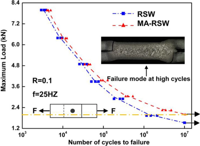
Fatigue testing results for welds of traditional RSW and MA-RSW of 1.25 mm DP780 at 7.8 kA welding current24
The fatigue life of the two types of welds gradually extends with the decrease in the maximum load; thus, the overall trends for the two curves are similar. Nevertheless, the fatigue lives of the MA-RSW welds are always longer than those of the traditional welds under the same maximum load, especially in high cycle conditions under relatively low loads. When the maximum load was set to 2.0 kN, the endurance limit of the EMS-RSW welds was nearly 1.1 × 10⁷, whereas it was only ∼1.4 × 10⁶ for the traditional welds. Obviously EMS notably improved the fatigue performance of RSW welds, especially in low load (high cycle) conditions. The improvement was attributed primarily to the better ductility of refined grains and the increased nugget diameter from the external magnetic field.
Comparison of weld lobes of traditional RSW and MA-RSW
To further investigate the practicality of the MA-RSW process, Li et al. compared the traditional RSW process and the MA-RSW process with 0.8 mm thick DP980 using a weld lobe diagram. 22 Results are shown in Fig. 23. The left boundary of the weld lobe diagram was determined by the minimum nugget diameter, which was ∼3.6 mm. The right boundary of the weld lobe diagram was determined by the threshold value of the welding current (beyond that, expulsion would occur). Because of the effect of the external magnetic field, the right boundary of the weld lobe diagram of the MA-RSW process moved left by nearly 400 A. Owing to the strong fluid flow driven by the circumferential magnetic force, a large quantity of high temperature molten metal would rush to the edge of the growing nugget, which would surely increase the nugget size at low current and short welding time, and induce expulsion at high welding current and long welding time. Owing to the increase in nugget diameter, the left boundary of the weld lobe diagram of the MA-RSW process also moved leftward by ∼400 A. Thus, the overall width of the weld lobe diagram remained almost unchanged. These results indicate that, under proper welding parameters, the MA-RSW process could be an alternative way to guarantee weld quality and at the same time reduce energy consumption.
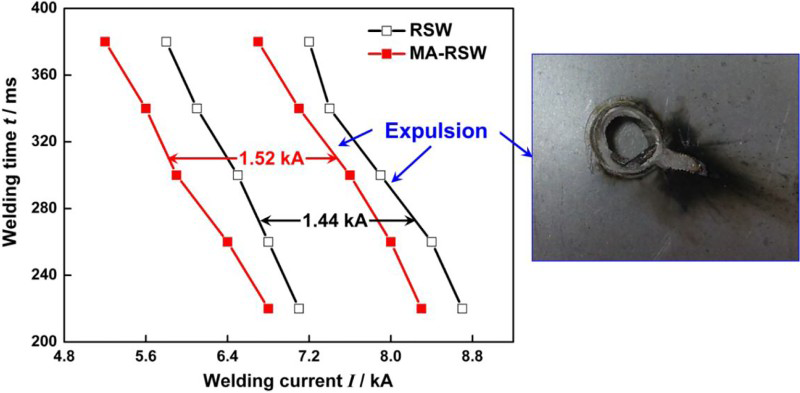
Comparison of weld lobe diagrams for traditional RSW process and MA-RSW process (WD = 3 mm)22
Conclusions
In this paper, the experimental set-up and mechanism of the MA-RSW process and its effectiveness in improving weldability of AHSS are reviewed. The following conclusions can be drawn.
An axisymmetric external magnetic field is the optimal mode for the MA-RSW process. This design produces two kinds of orthogonal magnetic force fields in the MA-RSW process. The induced magnetic force lies in the symmetric plane of the electrode and produces an in-plane symmetric flow in four symmetric quadrants. The external magnetic force is perpendicular to the symmetric plane and produces an out of plane centrifugal flow in the circumferential direction. Under the action of the induced magnetic force field, the flow pattern of the molten metal in a weld nugget changes with time for the non-uniform magnetic force field. Initially, the molten metal flows into the centre of the nugget along the faying surface, but the flow reverses as the size of the nugget increases. This kind of flow causes a relatively homogeneous temperature field in the nugget and a stagnation stage in temperature evolution. Our experimental results indicate that Cunningham and Alcini's hypothesis on flow pattern is incomplete. However, the flow caused by the external magnetic field, which intricately couples with the flow caused by induced magnetic field, needs further study. Magnetically assisted resistance spot welds were generally dog bone shaped (i.e. the nugget edges were thicker than the middle). In addition, with the increase in the external magnetic field intensity, the nugget became even wider and thinner. A single sided MA-RSW process also enlarges the weld nugget, but it produces a non-symmetrical dog bone shaped nugget. Compared with the traditional welds, all the magnetically assisted welds exhibit higher tensile shear strength, stronger energy absorption capacity and a higher probability of button pullout fracture. Such improvement of mechanical performance is more obvious for welds under relatively low welding current. The MA-RSW process affects the weld microstructures. The grain alignment in the weld fusion zone under the external magnetic field is less directional along with the refined crystal grains. Sizes of shrinkage cavities are much smaller. In addition, more stretched dimples are found in the fracture surfaces of welds made under the external magnetic field. A weld lobe diagram of RSW DP980 steel reveals the effect of the external magnetic field by shifting leftward for nearly 400 A, while the width remains almost unchanged. This suggests that the MA-RSW process could be an alternative method to ensure weld quality while reducing energy consumption.
Outlook for future
The MA-RSW process has been demonstrated to be able to improve the resistance spot weldability of AHSSs by increasing nugget size using the enhanced flow of the molten metal in the heating stage and homogenising and refining microstructures using the inertia flow of the molten metal in the cooling stage. However, further studies are needed before this technology can be widely implemented in industry.
Flow mechanism under an external magnetic field: the fluid flow and heat transfer under an induced magnetic field have been well studied; however, the circumferential flow and its interaction with the in-plane flow are still unclear. The coupled fluid flow will surely affect the flow pattern and will enhance the flow in the molten nugget. The enhanced flow will produce a more significant effect on both heating and cooling stages and on the final weld quality. However, for an out of plane flow, a 3D fluid dynamics model is needed. Moreover, the interaction between the in-plane flow and the out of plane flow is complicated and thus poses a challenge to convergence of the calculation. Evaluation of the dog bone shaped weld nugget: the external magnetic field produces a wider and thinner dog bone shaped nugget. A larger nugget is good for performance. However, the reduction in penetration is not. The manner in which the change in shape affects the weld quality and how to control the balance between nugget size and penetration should be studied further in terms of static strength and fatigue property. Development of an excitation coil based magnetic field source: in the current study, permanent magnets were used to produce the external magnetic field. The advantages of permanent magnets are their high magnetic energy density and the possibility of reducing their size. On the other hand, permanent magnets are brittle and easily affected by high temperature, and the user does not have the flexibility to change the magnetic field strength based on specific requirements. Thus, it is necessary to develop an excitation coil based MA-RSW system. With the flexibility of a magnetically assisted system, the user could easily change the EMS intensity by adjusting the excitation current; the user could switch the EMS effect on or off as desired during the welding process and could adjust the intensity in the middle of the welding process. The size of the coils should be minimised through innovative design. Integration of the MA-RSW system with a welding gun: in the current literature, the permanent magnets were externally attached onto a welding gun. Because the diameter of the cap shank on the gun is much larger than the weld nugget, the effective radial magnetic force in the nugget area is very low compared with the maximum magnetic flux density that the magnets could produce. An integrated compact design of the MA-RSW system capable of producing a strong radial magnetic field in the nugget area is strongly needed.
Footnotes
Acknowledgements
The authors would like to acknowledge the support of the National Natural Science Foundation of China (grant nos. 51275300, 51322504 and 50821003), Program for New Century Excellent Talents in University by Ministry of Education of China (grant no. NCET-12-0361), the Program of Introducing Talents of Discipline to Universities (grant no. B06012) and the Research Project of State Key Laboratory of Mechanical System and Vibration (grant no. MSVZD201411). The research was also supported in part by the US-China CERC-CVC Program.