
Abstract
Welding for large mobile mining equipment commonly used in the oil sands mining industry represents a unique aspect of the construction and mining heavy equipment industries. Low volume, high production capacity dominates, differing from the high volume, low production typical of the on-highway cartage automotive industry. The use of robotic welders is increasing but remains predominantly avoided due to the high cost associated with fixturing and positioning of large structural components, compounded by tolerance concerns. The main issues facing weld performance are fatigue and wear. A large portion of the ultraclass large mobile mining equipment industry focuses on fast field repair techniques, dominated by shielded metal arc welding, while in shop repairs, gas metal arc welding remains the preference.
Introduction
Welding in the large mobile mining equipment (LMME) industry, specifically focusing on such off-highway operations in the Canadian Oil Sands mining region, offers unique challenges not seen for the majority of welding applications in the automotive industry. Typically, welding in the on-highway automotive industry focuses on the joining of thin gages and light alloys for extended lifetimes, whereas the off-highway LMME industry focuses on joining thick steels and highly resistant materials with the expectation of short operational lifetimes due to the rugged environment and operational conditions. LMME is extensively used in the extraction, transportation and processing of the oil sands mining industry. The equipment used in such application are expensive, and therefore, the issues associated with welding of these large pieces of equipment are uniquely relevant to this heavy faction of the much larger overall global automotive industry.
Rigid body, end-dump ultraclass heavy haulers used in the oil sands mining industry represent some of the largest examples of LMME. These heavy haulers were first introduced in the oil sands region in concert with matching 3 to 4 pass loading capacity rope shovels and hydraulic excavators to provide a redundant truck shovel mining method. This replaced the previous bucketwheel excavator or dragline bucket wheel reclaimer in concert with mobile conveyor systems that were previously used from the 1960 to the 1990 as the primary mode of bulk excavation and transportation of oil sand to the on-site extraction plants that would separate the bitumen from the sand media.
Examples of ultraclass haulers, defined by those that have rated capacities exceeding 320 ton, are the Caterpillar 797 (360 ton), 797B, 797F (400 ton), Komatsu 930 E (320 ton) and Liebherr 282 (400 ton). The estimated cost of this class of hauler has been reported in the $5–6 million range, 1 and it depends on the number of units ordered from an original equipment manufacturer (OEM) and the previous maintenance relationship between the OEM, their service provider and the operation client. An example of one of these heavy haulers is shown in Fig. 1. Although this paper focuses on the application of such haulers in the Athabasca oil sands region, these units are employed globally in other mining applications worldwide for energy resources, industrial minerals, and base and precious metals.
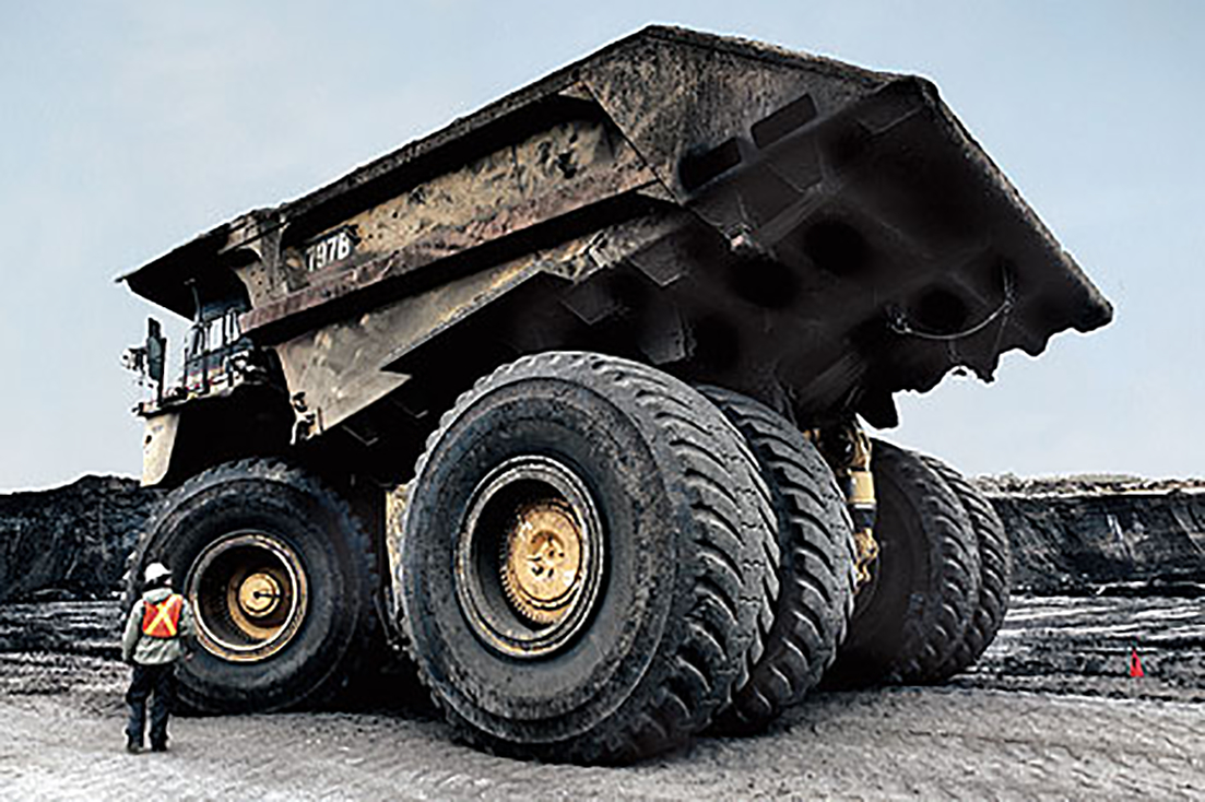
Caterpillar 797B heavy hauler in service in Athabasca oil sands 2
The electric rope shovels, such as the 4100 TS and BOSS units of Joy Global (shown in Fig. 2) or 7495HF units of Caterpillar (formerly Bucyrus) and the hydraulic excavators, such as the Komatsu PC8000, Caterpillar (formerly Terex O&K) RH400 or Hitachi EX8000, represent the tools that load ultraclass heavy haulers in four to five passes in open pit operations (in each pass, the shovel dumps its load into the waiting truck; it takes four or five shovel loads to fill the truck). Costs of hydraulic excavators range from $15 million to $20 million. In contrast, electric rope shovels range from $35 million to over $40 million. In general, ultraclass electric rope shovels outweigh ultraclass hydraulic excavators at 1 300 000 kg versus 850 000 kg, with rated shovels truck dipper capacities of 44 m3 versus excavator bucket capacities of 34 m3.
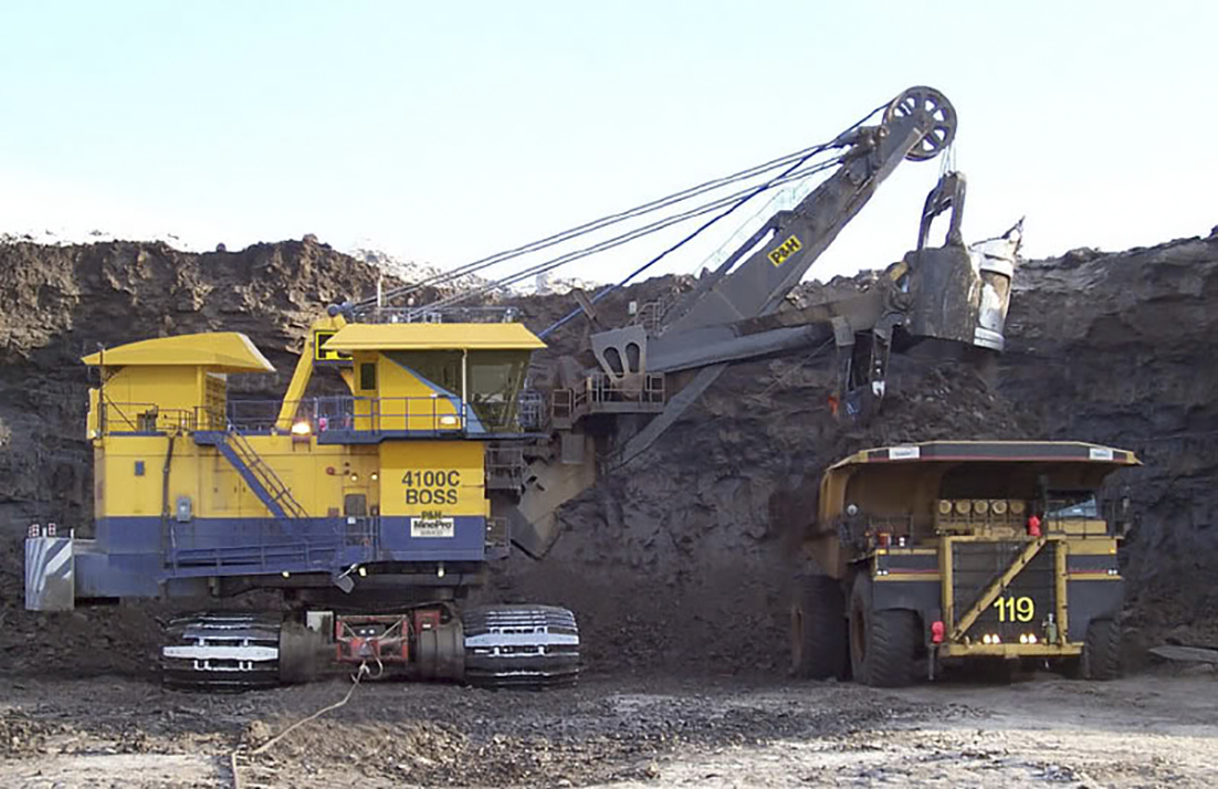
Joy Global 4100C BOSS electric rope shovel loading a Caterpillar 797 heavy hauler 3
In the major support equipment category for ultraclass equipment, Caterpillar D11 and Komatsu 475 bulldozers are frequently used for waste dump management, tailings structures and mine road construction, the latter being of prime importance ensuring the integrity of heavy hauler performance in transporting ore from loading device to processing plant. Resilient modulus engineering design techniques represent the most recent road design strategy, commensurate with the unload–reload activity of heavy hauler traffic, which is rated for a life cycle capacity of 5–10 million metric ton of material movement. A Caterpillar D11-R bulldozer highlighting the wear resistant overlay plate covering the blade is shown in Fig. 3. Such bulldozers are key tools for oil sands operations due to their versatility and ease of mobility from one functioning area to another. This leads not only to high abrasive wear of the blade, particularly at the leading cutting edge (shown at the blade/ground contact in Fig. 3), but also for the undercarriage and track/ground contacts. The subangular nature of the oil sand, its 80% and above quartz content, and the presence of appreciable garnet and other heavy minerals create a highly abrasive media for the carbon manganese steel base such that chrome and tungsten carbide overlays are employed for protection.
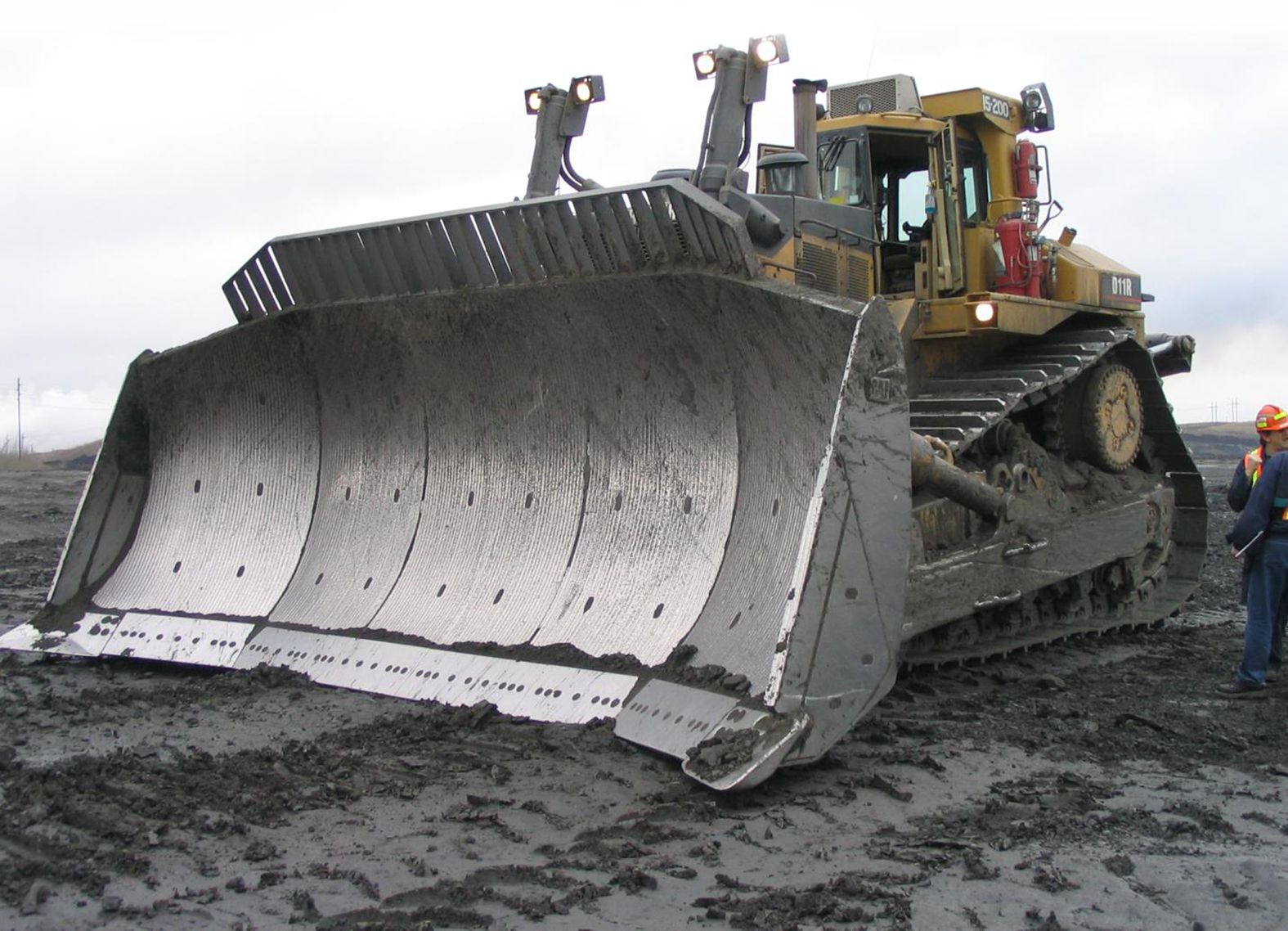
Caterpillar D11 heavy dozer in service 4
The focus in this paper is to identify and discuss the issues associated with the welding of these types of equipment not only at the manufacturing stage but also as maintenance and repair conditions are encountered. General materials concerns are initially discussed, followed by a focus on the two principal damage issues associated with LMME in the oil sands: fatigue and wear. 5 The authors conducted in depth interviews with people directly involved in the manufacturing and maintenance of LMME focusing on the oil sands mining industry. One of the main challenges in synthesising welding knowledge associated with LMME is that many manufacturing issues are proprietary and repairs that are made are typically conducted in a hurry, with minimal records retained despite the best efforts of OEMs to provide weld repair protocols within the auspice of the warranties set for given components and equipment models. In many cases, end users have established protocols based on years of experience with minimal documentation. In many cases, only verbal confirmation takes place with OEMs before proceeding with repair and replacement activities. As with the telling of stories, procedures handed down by word of mouth from one generation of weld maintenance technologists to the next, the criteria and reasoning associated with practices and procedure are often lost, but the application is retained with the notion that repairs ‘have always been done this way’.
Materials concerns
Materials selection is a major issue in the manufacturing of heavy equipment such as ultraclass trucks for oil sands and other bulk surface mining application. One of the main design criteria for the materials used for heavy equipment is reducing the weight of the various components. 6 This is paradoxical given that the overall gross vehicle weight of a full 400 ton hauler is 510 000 kg1 (360 ton payload plus 150 ton truck). To achieve the lowest weight, designers attempt to employ as little material as possible, without sacrificing either structural integrity, impact resistance, fatigue life or durability. As heavy haulers have progressed from 50 ton payload through 100 ton, 220 ton, 240 ton, 320 ton, to the ultraclass category, the achievement of higher payload has been partially achieved using more advanced structural designs and use of materials permitting a significant reduction in tare weight (empty vehicle weight). The expectation in operational structural performance for the ultraclass units at 360 ton payloads and above (a jump of 50% in payload from the previous size class at 240 ton) is the largest relative increment ever attempted in performance expectation for heavy hauler designs. The challenge of the nominal increase in load is compounded by the fact that during operation, heavy haulers are expected to withstand up a to 2.5g factor during loading.
Quenched and tempered (QT) steels are used during the manufacturing of heavy haulers to maximise the strength to weight ratio. Generally, QT steels can have issues as a result of welding, particularly in the heat affected zone (HAZ) with loss of strength and properties. The HAZ in QT steels is particularly susceptible to hydrogen induced cracking issues, which are caused by several factors including excess diffusible hydrogen in the weld pool, tensile stresses and brittle microstructure. 7 The risk of delayed hydrogen cracking increases as the hardness of the microstructure increases, 8 which is a major concern for manufacturers using high hardness QT steels. Table 1 shows a summary of the compositions of several frequently used QT steels and basic mild steel; the latter makes up the majority of the steel used in the LMME industry.
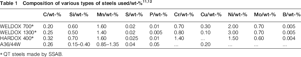
QT steels made by SSAB.
The weldability of the QT steels is highly dependent on the heat input of the process as well as the consumable selection. Another key issue of welding QT steels is that consumable choice must match the strength of the QT base material. This is generally achieved using a high degree of alloying, which increases the carbon equivalent of the weld metal 9 and therefore increases the hardenability. Similarly, processes such as flux cored arc welding (FCAW) must be employed with careful consumable selection, as FCAW has been linked to delayed hydrogen cracking in QT steels. 10 Previous work by Magudeeswaran et al. found that low hydrogen ferritic FCAW consumables can be detrimental to delayed hydrogen cracking resistance. 10
HAZ softening is frequently present in QT steels 13 ; this phenomenon is linked to the heat input during welding and severely weakens the joint integrity.13–15 Heat input must be carefully balanced to avoid HAZ weakness or lack of fusion. A heat input that is too low may result in lack of fusion, but conversely, if the heat input is too high, the HAZ will grow in size and the risk of detrimental microstructure increases. 16 This balance is represented graphically in Fig. 4.
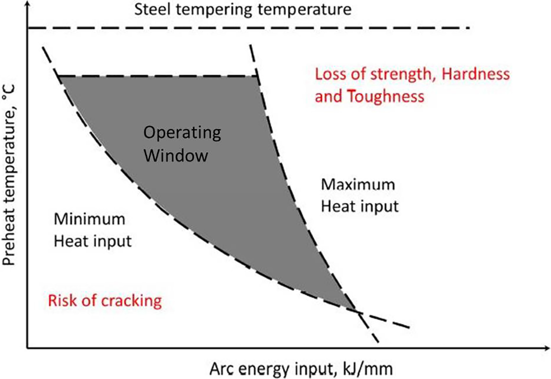
Heat input and preheat effect on material properties (modified from Australian Welding Research Association 17 )
Aside from QT steels, many components are manufactured from structural carbon steel. There are several issues that exist for the welding of these steels, but the main issues focused on in this paper are the welding of thick plate and placing welds in cold environment service. The plate thickness employed in the LMME industries typically range from 10 to 80 mm; this high thickness necessitates the use of multipass welding. Multipass welding involves many different techniques used to reduce the overall heat input and the amount of distortion present. Maintaining the interpass temperature during multipass welding is important for avoiding microstructural issues within the HAZ and previous passes following the completion of the weld. In a shop environment, it is generally possible to maintain a consistent temperature. In the cold climates of the oil sands in Canada, it is difficult to achieve a consistent interpass temperature. Generally, resistively heated blankets are placed over the welds to maintain the heat between passes, but it is often insufficient to avoid microstructural issues due to both the climate and the inevitable cooling that occurs between the heat blanket removal and the action of applying the next welding pass.
Owing to the amount of weld metal deposited in multipass welding, distortion effects are large and problematic for the LMME industry. General techniques such as minimising weld material and weld passes are not as effective because of the scale and the necessity for mechanically sound weld design. Focus is therefore placed on patterning welds, preheating and postweld heat treating to help minimise distortion effects. 18 Clamping and other techniques are difficult and expensive to utilise. The application of high productivity, low heat input processes such as laser hybrid welding cannot effectively be applied to large scale equipment as the required fit up is extremely difficult, given the sizes and forces at play.
The use of low hydrogen welding consumables has, in recent years, greatly increased for welding of thick high strength steels. Cold cracking following welding can occur in all steels and is evidenced by the appearance of cracks in the weld and HAZ either immediately after welding or anywhere from a few minutes to several hours afterwards. Two main solutions are typically used to avoiding delayed hydrogen cracking in LMME, the first of which is preheating to avoid the rapid cooling, which leads to the formation of martensite and aids in hydrogen removal. The other option is employing low hydrogen consumables, which is vital in cases where preheating is not possible. 19 For LMME applications, a consumable is designated as ‘low hydrogen’ when its results in < 16 mL of hydrogen per 100 g of weld metal. 19
Aside from steel thickness, welding equipment and consumables for LMME in Canada must be prepared for use in cold climates to deal with the increased risk of brittle fracture. 20 The main concern is the toughness of the weldment following welding due to the brittle microstructure that is prone to forming within the HAZ. Generally, all welding procedures used in the manufacturing of LMME to be used in cold climates have Charpy impact toughness or crack tip opening displacement requirements tested between − 40 and − 60°C. 21 The minimum temperature recorded for the oil sands area in Canada is of the order of − 50°C, highlighting the need for low temperature testing. 22 The most common techniques for producing high impact toughness at low temperatures for welds are heat input control and consumable chemistry. 23
Fatigue
Fatigue is encountered frequently by LMME used in the oil sands due to the near continuous operation schedule of the industry. The high frequency of use, in combination with the high stresses that the equipment is subjected to, results in many fatigue related failures and repairs. The mitigation of fatigue is difficult during operation, and therefore, much of the effort is made during the design and manufacturing stages.
Welds can serve as particularly fatigue prone zones, as the material surrounding the welds and the welds themselves are often brittle and cannot resist cyclic loading well. In general, some of the welds that are the most susceptible to fatigue failure are the long seam welds at the core of the structures. Many companies weld solid steel castings around long welds to protect the welds and provide improved fatigue resistance. This can be seen in Fig. 5. The use of castings is somewhat misled however, as the structure becomes stiffer and less able to handle cyclic loading. The use of torsion tubes in place of the steel castings would likely be more beneficial, as they would allow for the deformation to be absorbed by the torsion tubes.
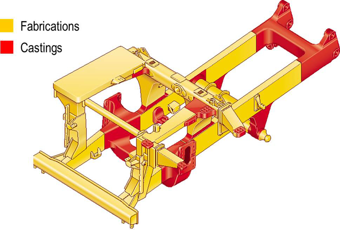
Heavy hauler truck frame with castings
On the frame of the heavy haulers, there are certain high stress points that are more susceptible to fatigue failures. Figure 6 illustrates one such truck frame where the areas of high stress are around the welds adjacent to pins and bushings, where sharper structural curvatures approaching the form of a corner are often encountered. Because of their size, hauler parts are shipped separately and must be reassembled by welding on site. Often, parts are shipped long distances crossing different climates and are not always given proper handling. This means that upon reassembly in the oil sands, warping and deformation that occurred during transit causes significant difficulties. Many of the pins and bushings are welded into place to keep the various structural components in position, but due to the tolerance issues created during loading, shipping and unloading, these welds are often under high residual stress and therefore vulnerable to fatigue failure. If any structural protrusion receives a sharp loading event, even in the action of being lifted and then placed onto an assembly preparation surface, where the protrusion made the initial impact contact with the surface, it is likely to receive loads higher than intended during operation. Lifting crews are typically unaware of the significant decrease in fatigue life as a consequence of seemingly minor events during assembly.
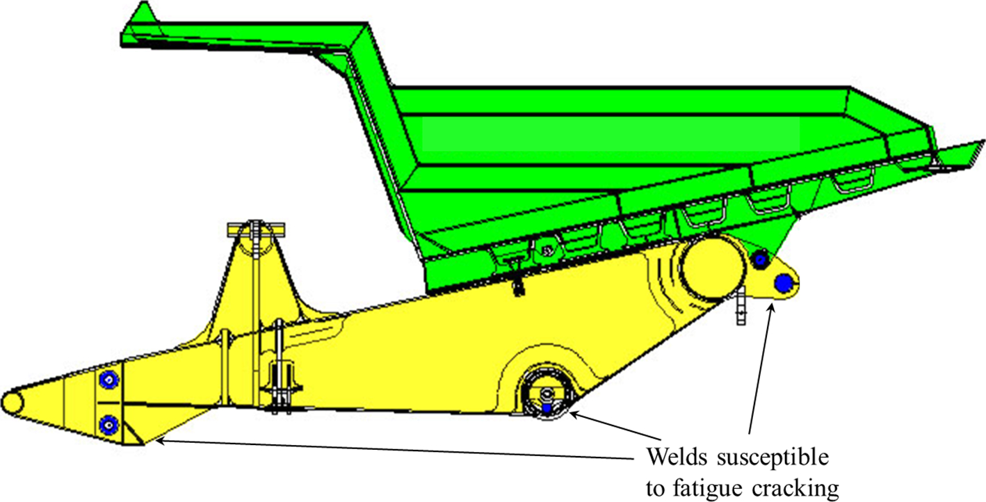
Side view of a heavy hauler truck frame (yellow) with mounted truck body (green) highlighting areas susceptible to fatigue; length of this component is of order of metres
Similarly to heavy haulers, ultraclass electric rope shovels, representing the larger of the shovel loading units, also suffer heavily from fatigue issues in several areas. Within the carbody, as the core of an undercarriage for an electric rope shovels, there are often cracks along the main seam welds indicated in Fig. 7. These cracks actually develop around the periphery of the carbody, where maximum displacement and strain occurs during operation of the structure, and spread quickly to other key seam weldments.
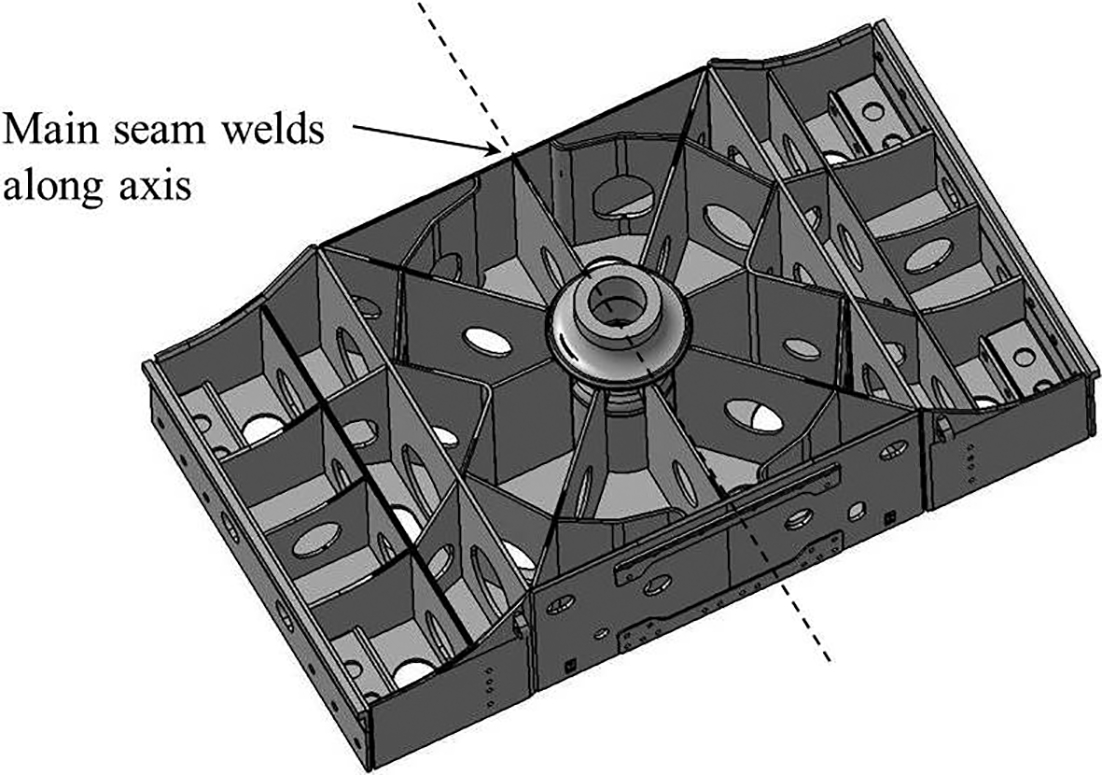
Electric rope shovel carbody structure with main seam welds indicated 6
The other major issues of fatigue in welds on electric rope shovels occur in the boom leading towards the sheave wheels (the rollers at the end of the boom that direct the wire hoist ropes). Owing to operation at high stresses, the welds on these booms often begin to fail near the boom foot and spread upwards towards the sheaves. To keep these rope shovels in service and avoid excessive downtime, common field repairs involve welding additional steel fish plates over and around the crack areas. The intention of these reinforcements is to help strengthen the welds; however, these reinforcements result in stiffening of the boom welds, making them more susceptible to fatigue crack growth. It is common to find field maintenance groups chasing cracks up the boom one fish plate at a time until the sheave wheels are encountered, thus creating a boom assembly and held together essentially with fish plates.
Steps that are taken to account for fatigue around welded components include careful procedural and material selection, as well as consideration of specialty consumables aimed at mitigating welding induced stresses. Lower transformation temperature (LTT) consumables are a specialty group of welding consumables designed to reduce the distortion and residual stress associated with welding to increase the fatigue strength of weld joints.24–28 LTT consumables accomplish the reduction of undesirable weld stresses by inducing a martensitic transformation towards the end of the cooling cycle, thus creating favourable compression residual stresses near the weld toe. 29 This carefully targeted martensitic transformation is accomplished with the right choice of alloying elements, mainly Cr, C, Mn, Ni, Si 30 and, to a less extent, Mo in an effort to lower the martensitic start temperature. The use of LTT consumables has also been shown to have higher hardness and tensile strength than typical base materials. 31 The minimisation of distortion effects is illustrated in Fig. 8. 6
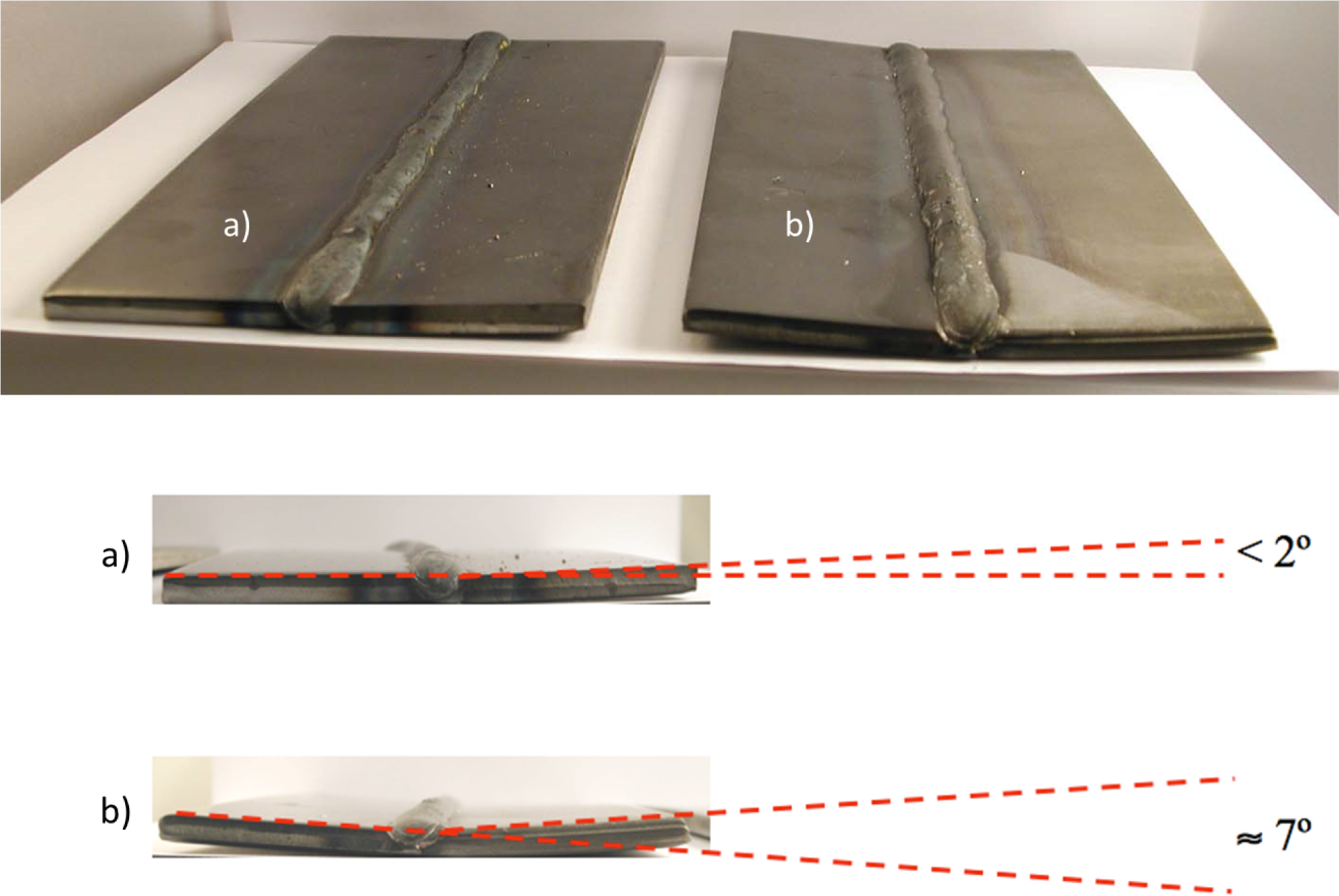
Welding coupons showing distortion following a welding using LTT consumable and b generic stainless steel consumable 6
Although LTT consumables do offer certain advantages over traditional consumables, they are not widely available or used. If they are employed, it is done sparingly at locations of high fatigue. At these targeted locations, LTT consumables are used only as a cap pass to minimise distortion effects. The main reason for their limited use is the large expense. These consumables are only employed during manufacturing and are not used during repair.
A strategy growing in relevance for mitigating the effects of fatigue on structural welds is the prediction of fatigue lifetime. Typically, in the automotive industry, fatigue failures are rare as components are rarely exposed to overload stresses above their yield strength. LMME, however, is frequently exposed to stresses beyond their yield stress. Each of these incidents lowers the total fatigue life of the structure, which leads to unpredictable premature failures. An example of a data set showing the cyclic loading as a dimensionless g level force acting at the rear suspension frame contact pins for a heavy hauler is shown in Fig. 9 and was recorded over ∼30 min of operation in a heavy hauler operating in the field. The data recorded indicate several high stress events (defined as peaks above the 1.5g datum) such that a fatigue inducing event is imparted to the main frame structure with every peak event. The use of a dimensionless loading evaluation allows for comparison to other unloaded points within the same structure. These high stress events are generally the result of carrying unbalanced payloads and operating on uneven running surfaces. Further analysis of Fig. 9 shows that either left rear or right rear suspension loading dominates. The magnitude of the peak loading and the frequency of the cyclic activity are directly related to the fatigue damage incurred by the frame and, given the fatigue properties of the structural material, give an understanding of the frequency of damage and associated crack repair.
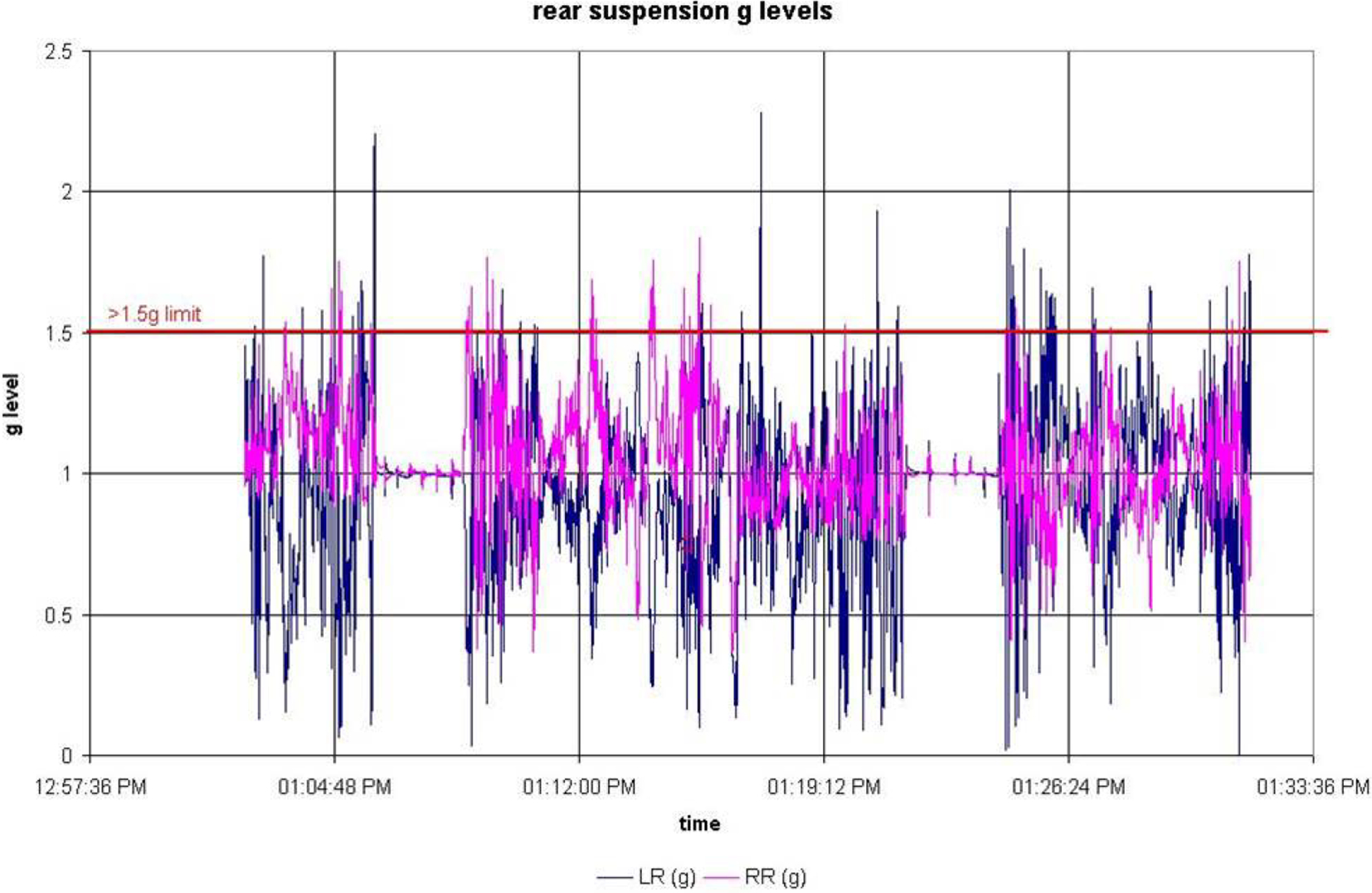
Cyclic loading on rear axle of heavy hauler truck
The manner in which the truck is loaded by an electric rope shovel is of great concern, but one that is not wholly in the control of the shovel operator as the oil sand geology tends to create clumping that manifests as uneven loading of the truck bed, creating an unbalanced load. This generates high stress events on a suspension frame contact point translated to adjacent frame welds.
Another strategy that is employed to reduce the frequency of fatigue related failures on LMME is altering the bead geometry. 32 Bead geometry is almost always altered through grinding following welding. The main reason for grinding is not only to remove surface roughness but also for the elimination of weld geometries with high stress concentrations. The higher the stress concentration at a point, the more susceptible it will be to fatigue failure. 33 Sharp variations in geometry at the toe of the weld as seen in Fig. 10a generally lead to these high stress concentrations. The most common solution is to create a concave profile for the entire bead as seen in Fig. 10b. The creation of the concave shape, however, leads to a loss of weld metal and therefore is detrimental to the mechanical properties of the weld. The best solution is to maintain a flat bead geometry with curvature at the toes of the weld, 34 which can be visualised in Fig. 10c. A large difficulty when applying these ideas to welding in the LMME industry is the inability to ensure consistency throughout the grinding of a component. Owing to the scale of the equipment, even small variations in the radius at the toe of the weld prove problematic as they are carried out over a large area.
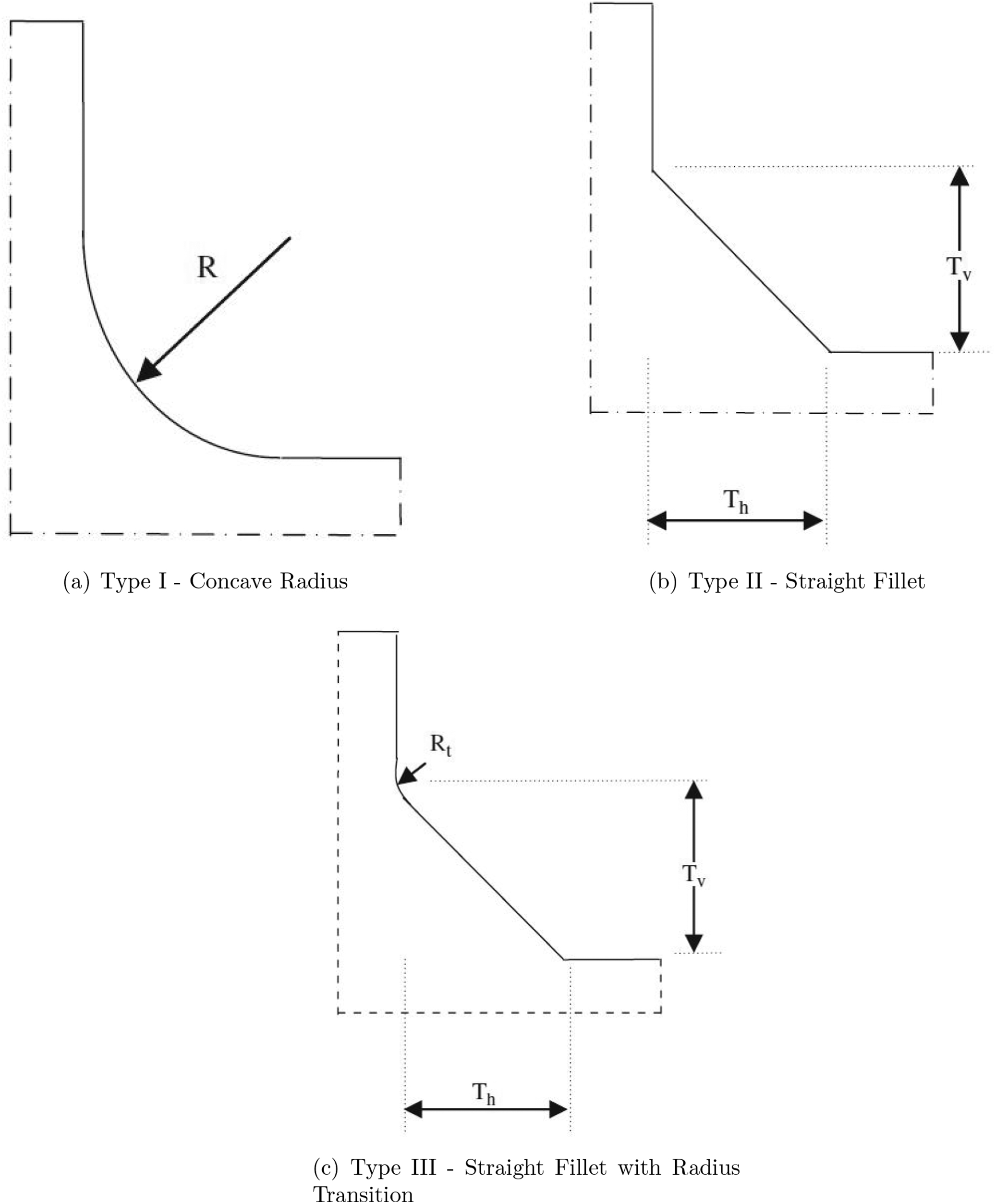
Weld geometry profile types 34
Wear
Wear is another prominent issue for heavy equipment in the oil sands. The estimated cost of wear replacement parts and labour is $40 million per year 35 for a single sample operation. Owing to the significance of the potential cost of wear, materials selection is crucial in both plate liners and overlay products.
The plate liners used are typically QT steels for their high toughness and impact properties. These liners are employed on various pieces of equipment, but the main uses are in the bodies of heavy haulers, for the internal walls of rope shovel dippers and for the active surfaces of bulldozer blades. Truck bodies not only undergo wear from the abrasive material as it flows from them during the load dump action at a crusher or dump area, but also when a dipper drops ore into a truck body, the ore load striking the body imparts a load impact to the body bed that creates a progressively increasing residual strain zone that affects the integrity of the body bed prematurely. Therefore, both wear liners and structural components of truck bodies are a frequent zone of repair and replacement. 5
For other machine components, where the wear is more directly imparted from the abrasive subangular quartz sand and heavy minerals in the oil sand, more severe measures are implemented including overlay plates, which are designed for low stress abrasion. An example of overlay plates in service are those employed for Caterpillar D11-R dozer blades, which utilise formed chrome carbide overlay (CCO) plates welded over the active blade face to provide increased wear resistance. 5 Similar CCO plates are also used as liners for heavy hauler bodies. CCO plates are targeted for use on heavy equipment where those components undergo direct contact abrasion.
Ni–WC overlays are employed in ground engaging tools such as tips and adapters that make up the teeth in shovel dippers and picks and liners that comprise crusher elements. These components experience extreme wear in the form of stress abrasion, gouging abrasion and impact wear. 36
Figure 11 shows an example of wear protection overlays in an electric rope shovel dipper. Ni–WC overlays are used on the teeth that are in direct contact with oil sand, while the inside of these buckets is coated in CCOs.
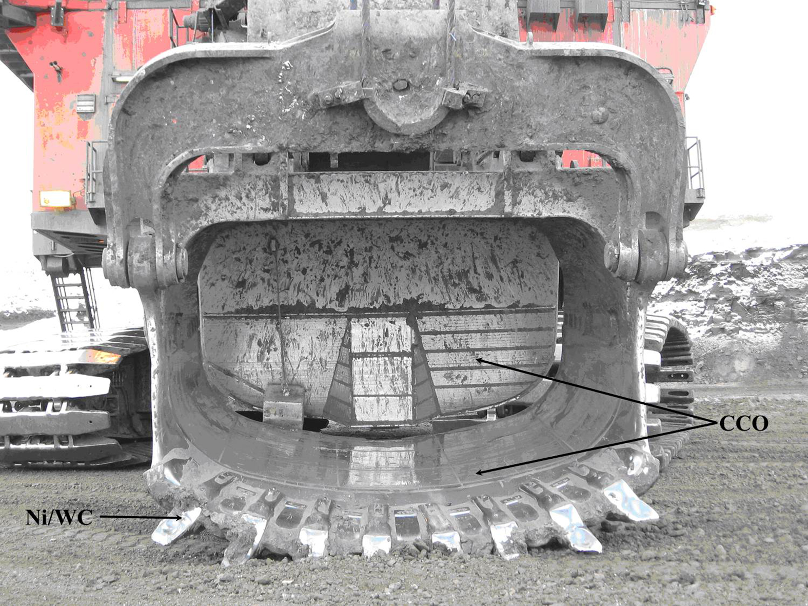
Bucket of electric rope shovel with both Ni–WC and CCO weld overlays 6
The production and application of these high wear resistance overlay products is difficult and involves careful planning. Typically, CCOs are deposited using submerged arc welding (SAW), 37 which is a high heat input process and is favourable for high productivity. Occasionally used CCOs are also deposited using MCAW. The main constituent in these overlays that provide wear resistance is primary M7 C3 chromium carbides, where M is mostly chromium. These primary carbides precipitate out during solidification and have a higher hardness than the surrounding eutectic colonies.38–41 The microstructure of CCOs is represented in Fig. 12. To obtain better wear results, the volume fraction of the primary carbides should be maximised. CCOs typically exhibit transverse cracking following solidification as a form of stress relief. 40 This phenomenon is often used as an indicator of high volume fractions of primary carbides and typically does not result in spalling or localised corrosion. A significant issue associated with the fabrication of CCOs using SAW is that the high heat input in the process leads to high levels of dilution, resulting in a reduced chromium fraction in the overlay, with the consequent decrease of primary carbide fraction in the overlay. Issues of dilution and segregation often cause a banded overlay microstructure. 35
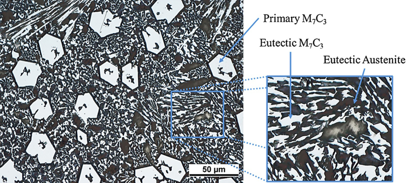
Typical CCO microstructure with hypereutectic composition 35
The other major overlay system that is employed is Ni–WC overlays. The amount of Ni–WC overlay used is less than CCOs due to their high costs but represents a much higher wear resistant system. Ni–WC overlays differ from many overlay systems in that the wear resistant features (tungsten carbides of high hardness and relatively high toughness) are not formed during solidification; instead, they are deposited into the weld pool. These overlays are typically deposited using plasma transferred arc welding or laser cladding systems for their superior heat input control. The desire for heat input control is rooted in the issues of dissolution that these carbides experience, as they are susceptible to melting. There are many different types of carbide particles that are manufactured to combat the dissolution effects such as W2C/WC eutectoid carbides coated in a WC, which is more resistant to dissolution.42–44 Spherical tungsten carbides have also been developed to combat dissolution using carefully tailored chemistry. 45 A microstructure of a Ni–WC overlay is shown in Fig. 13.
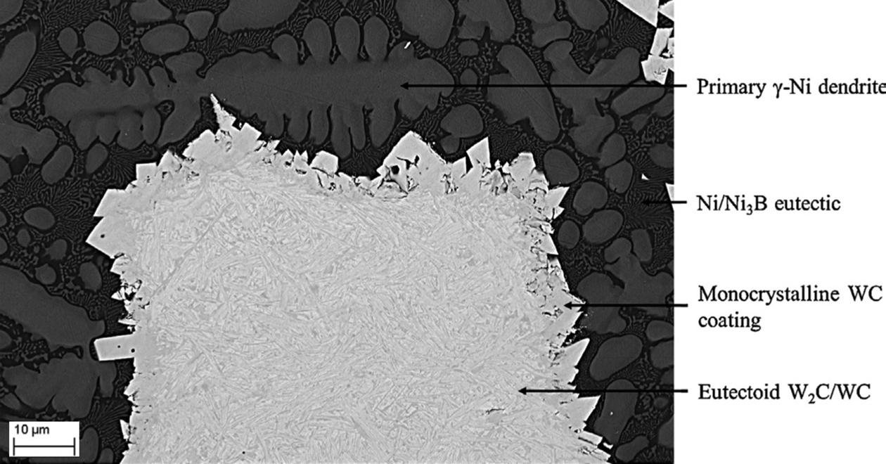
W2C/WC eutectoid carbides coated in monocrystalline carbide in nickel matrix 35
Repairs
Heavy equipment often undergo frequent repairs due to both the long periods of continuous operation and the difficult environmental operating conditions. Among these repairs, there are two main categories: critical repairs, in which a piece of equipment is unexpectedly damaged, and maintenance repairs, where rebuilding of a wear resistant surface is conducted to extend the mean time between replacement. An additional category is known as operational damage, which is anticipated and requires the replacement of a consumable component such as the wear resistant teeth on the dipper of a rope shovel as seen in Fig. 14. In general, repairs of LMME fall into the first category, where typically repairs and maintenance make up ∼30% of the total ownership cost of a piece of heavy equipment over the life of the asset.
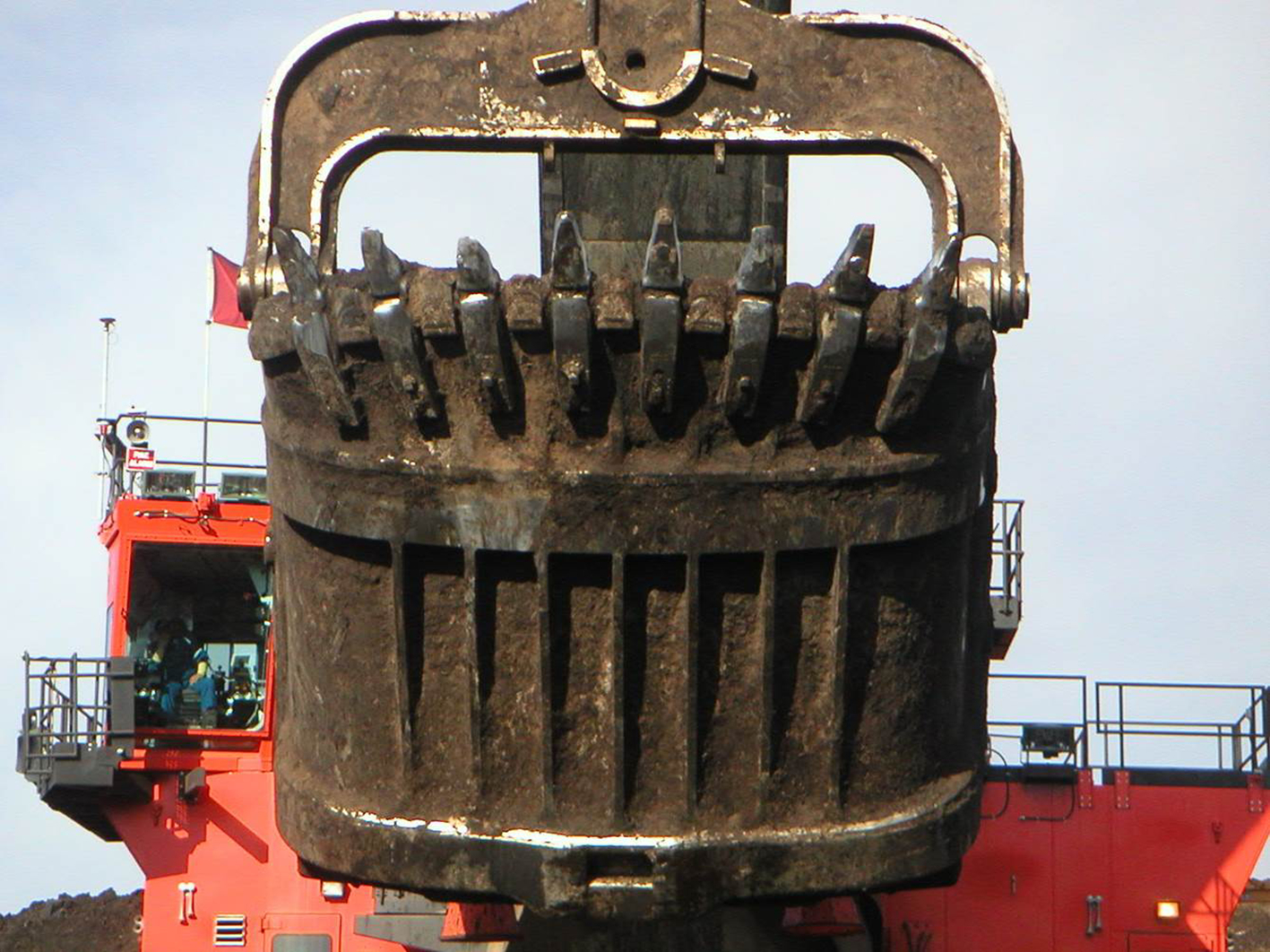
Wear on teeth of rope shovel bucket 6
Some of the main variables that come into play during repairs are the difficulty of the repair and the frequency of different repair types. These variables aid in the determination of the welding process and the consumables. For adaptability (i.e. the ability to weld out of position and in areas with tight constraints), simpler manual processes are often employed. The need for versatility in field repairs often means the use of the shielded metal arc welding (SMAW) process (‘stick’) and manual gas metal arc welding (GMAW). In the oil sands, it is difficult to convince qualified welders to adopt weld processes such as FCAW, which may have certain favourable traits. A large reason for the continued use of less efficient processes like SMAW is that the available workforce is more easily qualified to weld using it and there is no need for expensive training. The focus of repair is speed over potential quality gains; thus, alternatives such as FCAW or LTT consumables are typically overlooked. FCAW is growing more prevalent for repairs within the heavy equipment industry as a whole, but within the oil sands, it still sees infrequent use. 46
Automation systems are avoided for repairs of heavy haulers and associated LMME. Automated welding equipment is relatively costly and requires a high capital investment where fixturing and positioning is typically a 2:1 ratio for cost versus the cost of the actual automated welding device. 4 Outside cost issues, automated repair equipment is not always as adaptable as a highly trained welder. For example, in the case of heavy hauler bodies, several welders can weld simultaneously on the same structure. Automation was investigated as a possibility for repairs of these bodies, but the capital investment required was established as being too high. Safety concerns of mixing welding personnel in the proximity of the automation set-up simultaneously were also present. Robotic automation has been successfully applied to some very targeted components such as the rebuild of shovel track pads.
Throughout the estimated 10 year lifetime of heavy haulers, five truck bodies at 2 years per body will be employed. 6 Generally, OEMs produce the vast majority (80%) of truck bodies that are manufactured specifically for the hauler size class. However, after market bodies through manufacturers such as Trinity, Phillippi-Hagenbuch and Duratray are designed specifically for the mining operation as a function of broken ore material behaviour and payload carryng capability and often replace the bodies the hauler were delivered with from the OEM. Given the wide variety of uses that heavy haulers are exposed to, operational end users typically demand a specialised truck body design commensurate with their operating conditions, dominated by the geology. In many cases, the original body delivered by the OEM is not used in favour of a body that may also sport a higher payload capacity or wears out less rapidly due to the harsh operating conditions.
One of the main issues encountered when conducting repair welding for LMME is that the asset is operated in abrasive conditions that have large quantities of mud and dust. The surface of the equipment brought in for repair always requires cleaning, with water detergent washing followed by sand blasting being the commonly used technique. Sand blasting offers several benefits beyond preparing the part for welding. It is useful in identifying surface cracks in need of repair, as well as providing a degree of surface roughness, which helps any later applied finishing paint adhere to the surface, extending the lifetime of the equipment.
In general, all major weld repair on LMME involves complete gouging and grinding of the failed weld, followed by refilling of the weld joint. As previously discussed, SMAW is the most frequently used for field repairs, with AWS E7018 electrodes being the most commonly used. For more severe repairs, where the heavy haulers are removed completely from service, they are typically repaired in a shop environment. In these cases, the repairs are almost always done completely using the GMAW process. Typical Ar/CO2 gas mixtures (75–90% Ar with 10–25% CO2) are used in combination with GMAW wire consumables ranging from the lower strength AWS ER70S-6 to higher strength consumables such as AWS ER100S-G. Generally, welding in the flat position is preferred as it allows for use of thicker consumables (2.4 mm welding wire) and therefore higher deposition rates. In out of position welds, to maintain a consistent product, thinner wire (1.6 mm welding wire) is employed. A single truck body takes between 2–3 weeks to complete a repair and can cost between $145 000 and $187 000. 46
An issue encountered by LMME in the oil sands that requires repair work and is not often considered is corrosion. Although not frequent, corrosion failures do occur. An example of this is the exhaust system used on large trucks. In some cases, the exhaust is piped around underneath the truck bed to heat the bed in an attempt to prevent the contents of the truck from sticking, although this strategy has also gained claims that it does in fact exasperate the problem. A consequence of piping the exhaust under the truck body is corrosion difficult repair work.
Welding processes
The welding processes used for the welding of heavy equipment have some variation across the industry. In general, GMAW dominates as the main welding process for the manufacturing of LMME. The motivating factors for using GMAW as the primary welding process are based in cost and efficiency. SAW and FCAW are also employed in certain applications: SAW can be used on long welds in the flat position, and FCAW is used where there is concern about the weld properties.
The productivity of these processes is a paramount concern. As previously mentioned, companies using heavy haulers and associated equipment cannot afford lost production. Therefore, OEMs make great effort to enhance productivity wherever possible to ensure that the demand is met and that their product is one of the choices at the next purchase point. Unlike the majority of the on-highway automotive industry, where production lines involve continuous automation and robotic welding on many vehicles at the same time in a low mix high volume type of operation, heavy equipment production is performed to completion one vehicle at a time. Automation is employed wherever possible but is limited by cost.
Owing to the scale of the parts used in heavy haulers, automated welding processes are difficult and expensive to apply. Cranes are used to rotate and position equipment components and allow the welders and robotic welders access. Many of the components for heavy hauler trucks are too large to allow for full robotic welding, and as such, manual welding must be used. Automated welding relies heavily on the ability to appropriately position components for welding; therefore, it is used on long seam welds and easily positioned areas. In general, the positioning cost is just too high to justify an entirely automated process, such as employed in the on-highway automotive industry.
Another large reason for avoiding the use of robotic welding equipment is the issues associated with quality and consistency. Much the same as many manufacturers in the automotive industry, tolerances on components and parts are maintained strictly. The difficulty created with large components is that even very tight tolerances (for example, ± 0.01%) result in large gaps or inconsistent fit-up over the large size of the LMME. These gaps are often too big to be bridged by automated welding. With manual welding, this problem is better accounted for and in many instances avoided, but for robotic welders that rely on precise fit-up and touch sensing for welding, this type of high mix low volume welding is difficult.
Summary
Welding of LMME for the oil sands mining industry represents a unique sector of the global automotive industry. Off-highway mining and construction equipment is expensive and requires welding of thick high strength materials as opposed to the light alloys generally used for welding in the on-highway automotive industry. The main challenges facing the welding of modern LMME are HAZ softening, delayed hydrogen cracking, and embrittlement within the weldment and HAZ. These issues are generally dealt with using a combination of techniques including careful consumable selection (low hydrogen consumables), careful heat input selection to avoid both lack of fusion and rapid cooling, and pre- and postheating to avoid embrittlement. The thickness of these materials is also of concern for welding as mechanically sound joints are difficult to achieve. Multipass welding is almost always required, and therefore, techniques such as weld patterning and heat treating are used to mitigate the distortion effects that are typically tied to thick weld cross-sections.
The two main issues encountered by LMME in service are fatigue and wear. Fatigue lifetime prediction is growing in use but is difficult to apply due to the high frequency of high stress events that lower the number of cycles to failure and are difficult to predict. Specialty welding consumables such as LTT have been considered as possible solution to fatigue issues through the introduction of compressive stresses at the weld toe. LTT technology has not reached mainstream applications yet as they are not readily available and are expensive solutions. The most widely used technique for the reduction of fatigue failures for welding of LMME is grinding the weld toe to minimise stress concentrations.
The oil sands provide a highly abrasive environment, where wear issues are a large portion of the problems encountered. Generally, weld overlays products are applied to LMME. The majority of the overlays are CCOs that are applied as weld on overlay plates. Typically, equipment used for ground engagement uses Ni–WC overlays as they provide more wear resistance than the CCOs. Ni–WC overlays are far more costly than CCOs, which is why they are applied only in select applications.
Owing to the frequency and severity of the failures encountered by LMME used in the oil sands, repair considerations are important. Generally, all repair welds should be sand blasted and completely gouged before rewelding. Repairs are predominantly preformed in the field under harsh operational and environmental conditions, where cold climate concerns dominate in winter. The priority in the repair industry is a rapid turnaround time, and therefore, use of available personnel often results in the use of SMAW and GMAW, although FCAW is slowly becoming more common. Similarly, at the manufacturing stage, GMAW dominates in use by OEMs, with small applications of FCAW. Automation in welding processes is employed where possible, but dimensional inconsistencies and difficult positioning and fixturing of large components result in limited use of welding robotics. The use of automated welding machines for repair of LMME is rare.
As the future unfolds, there is likely to be an increase in the proportion of robotic welding equipment and positioners to further increase OEM manufacturing efficiency, although this will be highly dependent on the ability to produce tight tolerances for large components. Lower productivity processes such as SMAW are likely going to become less prevalent and be replaced with FCAW as the workforce receives training and acquires familiarity with the process. Increased use of FCAW should offer several advantages including increased efficiency, better mechanical properties and excellent protection of the weld. LTT consumables are likely o find a niche with OEMs if costs and availability are improved.
There are many issues associated with the welding of LMME operating in the oil sands. Many of the issues are difficult to avoid and mitigate, but the industry has a large incentive for finding solutions. The future of the LMME welding industry is intrinsically linked to the future of natural resource extraction. The oil sands and mining industries are expanding fields, and the emergence of alternative industries will play a major role in the volume of LMME required.
Acknowledgements
The authors would like to thank Blaine Stoesz, Sean Wakeham and Doug Schindel from Weldco Companies; Sheri Acheson from Syncrude; and Dr Fernando Martinez Diez from Caterpillar.