
Abstract
In this paper, the influence of friction stir welding process parameters and impact of tool geometry on the microstructural characteristics and tribological properties of AZ80A magnesium alloy are experimentally investigated. Tool with three different pin profiles at a constant tool rotational speed ω to feedrate υ ratio were employed. Additionally, detailed experimental measurements are also carried out on the hardness and wear losses of joints. The chemical compositions of fabricated joints are analysed using energy dispersive spectrometry. The taper cylindrical pin profiled tool exhibited sound joints under the 750 rev min− 1/75 mm min− 1 ratio. It is also found that the tool rotational speed plays a more significant role on the microstructural characteristics and mechanical properties of the joints, compared to feedrate.
Introduction
The increased demand for low exhaust gas emission, improved fuel economy and greater operating efficiency in the automobile applications is creating the necessity for a wider research in the area of light weight structural materials. 1 Being one of the lightest material under the metallic category, magnesium alloys in practical usage provide an extensive potential for weight saving in the automotive industries. 2 The promising characteristics of magnesium alloys such as good corrosion resistance, high damping capacity, greater specific strength, excellent stiffness along with easy castability and desirable capability for enabling the recycling process make them very attractive for aerospace and automobile sectors. Even though the wider use of Mg alloys requires feasible joining methods, there is still a lack of efficient and effective welding techniques for magnesium alloys.3, 4 Since the technology adopted for joining magnesium alloys is found to play an important role in the field of their application in structural components, additional care should be taken while selecting the joining processes such as welding for fabricating parts composed of magnesium alloys. 5
Friction stir welding (FSW), an innovative type of solid state welding technique invented and developed by The Welding Institute, can present higher potential for magnesium alloys 6 because it utilises a non-consumable rotating tool to produce frictional heat and thereby creating plastic deformation at the location of welding.7, 8 Investigations have been carried out on the FSW of magnesium alloys under various conditions and process parameters.3, 9–20 It is observed that many of the investigations have been carried out on FSW of AZ31B magnesium alloys3, 10–15 and very limited studies with AZ6116, 17 and ZK6018–20 magnesium alloys. Moreover, limited investigations have been made on the impact of tool profile and geometry during FSW of magnesium alloys. For example, Ganesa Balamurugan et al. 11 investigated the changes produced in the tribological and mechanical properties of AZ31B Mg alloy by the profile of the tool shoulder during the FSW, and the investigation revealed that material properties were determined by the strain hardening effect during the usage of tool with concave shoulder, whereas the material properties were determined by the grain size in the case of a tool with step shoulder.
Since the research works and experimental investigations focusing on joining of Mg alloys using FSW technique is very scant, a detailed experimental investigation on the effect of the tool pin profile on the microstructural characteristics and mechanical properties including tensile properties, hardness, percentage elongation, etc. is essential. As a result, this paper focuses in detail the FSW of AZ80A Mg alloys with three different tool geometry at a constant tool rotational speed ω to feedrate υ ratio of 10.
Experimental
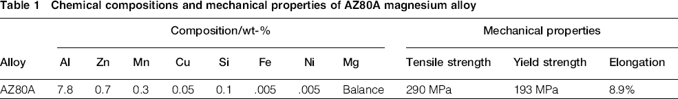
AZ80A magnesium alloy is taken as the base material in this present investigation. The required thickness of 5 mm of the AZ80A magnesium alloy was obtained by machining the rolled plates to the required dimension. The rolled plates are then cut to the required length and width (150 × 50 mm) using power hacksaw followed by the milling process. The chemical compositions and mechanical properties of the base metal, i.e. AZ80A magnesium alloy, are listed in Table 1. A square butt configuration was prepared to enable the joining of the AZ80A pieces together by means of FSW technique.
Chemical compositions and mechanical properties of AZ80A magnesium alloy
Friction stir welding machine
The FSW of AZ80A magnesium alloys using three different pin profiled high speed steel tools at a constant ω to feed υ ratio is performed using a specially designed semiautomatic FSW machine with a table size of 810 × 400 mm and a spindle speed ranging from 45 to 1500 rev min− 1 with a feed range of 0.25–500 mm min− 1. The machine is equipped with a spindle motor power of 5 kW, which provides a 3 ton mechanical linear axial force in the vertical direction. Moreover, the machine has a 510 mm travel distance along the X axis, 400 mm along the Y axis and 400 mm with respect to the Z axis.
Design of tool pin profiles
The tool geometry and design is found to play a major role in influencing the plastic flow and heat generation. The tool pin profile has a greater input on the material flow during FSW and the uniformity of the welded joint. The tool shoulder performs the function of generating most of the heat and also prevents the plasticised material from escaping the workpiece surface.20, 21 M35 grade high speed steel tools with three different types of pin profiles are used in this investigation. Different photographic views of these three different pin profiles, i.e. threaded cylindrical, straight cylindrical and taper cylindrical, are shown in Fig. 1, and their specifications and dimensions are summarised in Table 2.
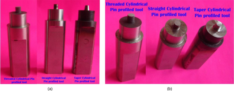
Photographic a front view and b tilted top view of three different tool pin profiles
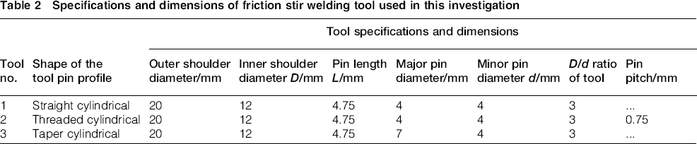
Specifications and dimensions of friction stir welding tool used in this investigation
Welding process parameters
This investigation is carried out at fixed conditions of tool rotational speed ω and feedrate υ such that ω/υ ratio is always constant, i.e., 10 in this investigation. Here, the term feedrate indicates the speed at which tool is moving. The constant ω/υ ratio was conducted in three different conditions, namely, condition I, 500 rev min− 1 to 50 mm min− 1; condition II, 750 rev min− 1 to 75 mm min− 1; and condition III, 1000 rev min− 1 to 100 mm min− 1. At the same time, other important parameter of the FSW process, namely, axial mechanical force, is maintained at a constant value of 3 kN throughout the joining process.
Analysis, results and discussion
Joint appearance and macrostructure of friction stir welded joints
The top surfaces of the majority of the welded joints were found to be free from visible defects. However, the cross-sections of some of the welded specimens are found to be present with tunnel defects in the various sections of the welded zone. These defects were observed when the welded specimens were analysed under the low magnification ( × 10) using the optical microscope. The effect of the three tool pin profiles on the macrostructure of the AZ80A weld cross-sections along the advancing side and retrieving side are clearly illustrated in Table 3. Tunnel defects are found to be present in the majority of the weld specimens fabricated using straight cylindrical pin profiled tool.
Effect of three different tool pin profiles and constant ω/υ ratio conditions on macrostructure
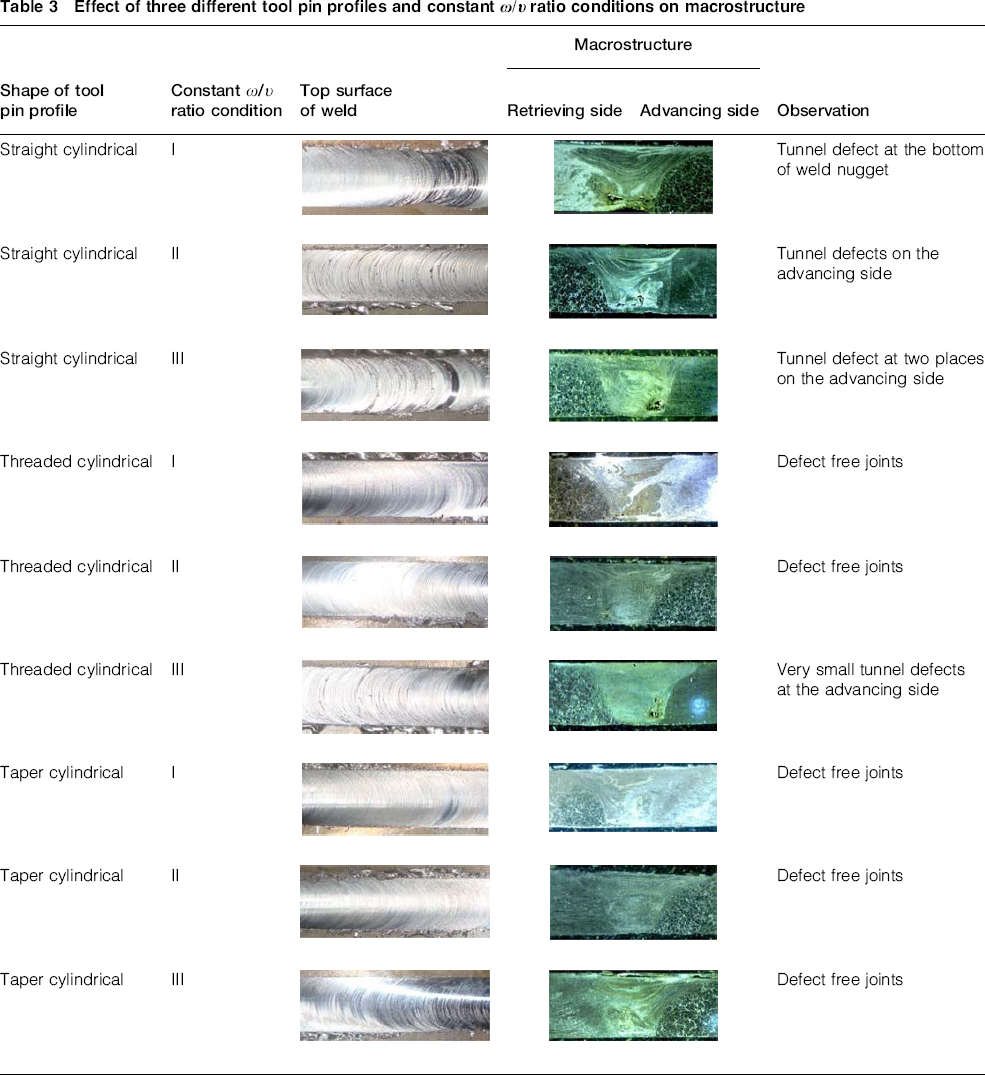
From this table, it can be observed that the joints produced using the threaded cylindrical and taper cylindrical pin profiles are free from defects, and the joints produced using the straight cylindrical tools is found to have a major defect termed as the ‘tunnel defect’, which eventually affects the mechanical properties of the joint. The tunnel defect is normally observed in FSW joints when the heat generation is insufficient and also occurs due to poor plasticisation of the metal. It is now practically evident that the tools with different pin profiles can generate variations in the plastic deformation. As a result, the straight cylindrical pin profile due to the absence of threaded structures on its surface and insufficient contact area could not create the required amount of plastic deformation due to low values of force in the downward direction. This indirectly resulted in an inadequate flow of material leading to the formation of tunnel defects in the nugget zone (NZ).
Microstructural characterisation
The optical micrograph of the base metal, i.e. AZ80A magnesium alloy, is shown in Fig. 2a, and it is found to contain basically coarse grains. Figure 2b shows the scanning electron microscopy (SEM) image of the AZ80A Mg alloy base metal used in this investigation.
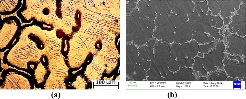
a optical micrograph; b SEMOptical and SEM images of AZ80A magnesium alloy (base metal)
The presence of coarse grains containing Al12Mg17 intermetallic compounds is observed in the SEM image. From the SEM image, it is also visible that the distribution of Al12Mg17 intermetallic compounds is not uniform in the base metal, and these intermetallic compounds are quite coarse. Apart from base metal, NZ, the thermomechanical transformation zone (TMTZ) and the heat affected zone are the three main separate regions in the macrostructure of the friction stir welded specimen.
Figure 3 elaborates in detail the microstructural graphs of the NZ obtained using the three different pin profiles and under the various ω/υ ratio conditions (conditions I–III). These micrographs clearly depict that the large size coarse grains present in the base metal have been transformed into equidistant fine sized grains in the NZ after FSW. Thus, an attempt was made to measure the size of the grains in the NZ of the fabricated joints by applying the HEYN's line intercept method. 22 Additional detailed investigation in the micrographs of the welded specimens proved that the dimension and specification of the tool pin profile plays an important role in affecting all the three different zones (NZ, TMTZ and HAZ) of the friction stir welded joints.
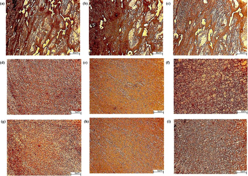
a tool 1 and condition I (no. 1-I); b no. 1-II; c no. 1-III; d no. 2-I; e no. 2–II; f no. 2-III; g no. 3-I; h no. 3-II; i no. 3-III)Microstructural graphs of NZ obtained using three different pin profiles and under various ω/υ ratio conditions
Grain size distribution
From the micrographs, it can be understood that there is an observable variation in the grain size. The coarse grains of the base metal have been transformed into fine grains at the NZ. Table 4 describes in detail the average size of the grains at the centre of the NZ obtained from majority of the fabricated joints in the abovementioned conditions. From this table, it is evident that, compared with the remaining two pin profiles, the taper cylindrical pin profile, i.e. tool 3, has produced a fine grain structure.
Average grain size at centre of NZ during all FSW conditions in this investigation
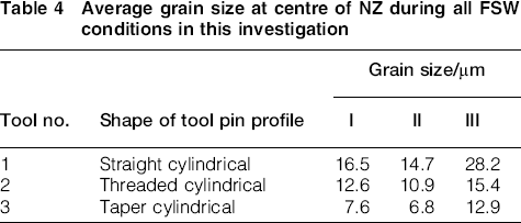
This is because the total contact surface between the AZ80A magnesium alloy specimens and the taper cylindrical pin profile is less when compared with the straight and threaded cylindrical profiles. As a result, tool 3 generates heat input and material flow at reduced levels leading to generation of the finest grain size. Thus, based on the grain size produced in the NZ using three different tool pin profiles, the ranking is listed as: grain size in FSW specimens using tool 1 (i.e. tool 1) > tool 2>tool 3.
Analysis on significance of ω and υ parameters
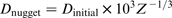
The equation establishing the relation between the temperature of the NZ and the parameters (ω and υ) during FSW process was given by Commin et al.
23
while investigating aluminium alloys
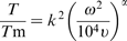
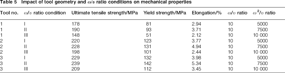
Considering the grain sizes ranging from 3 to 100 μm, an empirical model had been developed by Mukai et al.
24
The developed model is mentioned below
It is clearly visible from Fig. 3 that the microstructures are greatly influenced by the ω/υ ratios, and there will be an increase in the NZ grain size when this ratio is increased as ω2/υ. Based on this, for the different FSW conditions adopted in this investigation and by considering the size of the grains from Table 4, the NZ grain size ranking is given as: condition III>condition I>condition II. Thus, it can be understood that the tool rotational speed plays a more predominant role on the microstructural characteristics and grain size compared with the feedrate.
Tensile strength, yield strength and percentage elongation
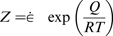
Two to three specimens obtained during FSW using three different tool pin profiles and under the various ω/υ ratio conditions are subjected to tensile testing, and the average of these results are tabulated in Table 5. From Table 5, it can be seen that largest values of tensile strength are found to be produced by taper cylindrical pin profile. Because of the fine grain structure, uniform grain distribution and defect free joints, yield strength and percentage of elongation values produced by this tool are also higher. Likewise, the use of threaded cylindrical pin profile has resulted in better values of mechanical properties when compared with straight cylindrical pin profile. Based on results obtained, specimens welded using different pin profiles are ranked for their mechanical properties as: tool 3>tool>tool 1.
Impact of tool geometry and ω/υ ratio conditions on mechanical properties
Scanning electron microscopy fractography of welded joints
Figure 4a shows the SEM image of the AZ80A Mg alloy base metal kept on the RS of the FSW process.
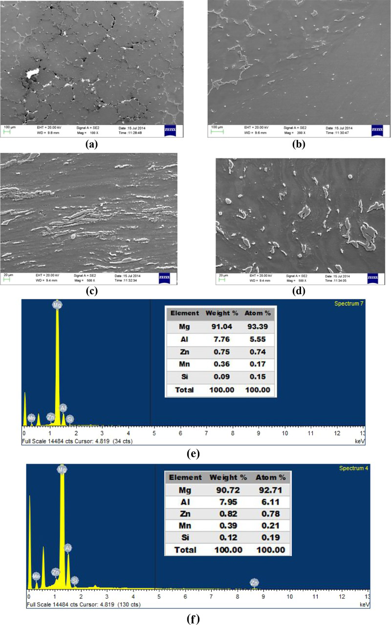
a base metal; b heat affected zone (HAZ); c nugget zone; d thermomechanical transformation zone (TMTZ); e EDS composition and quantitative results of base metal; f EDS composition and quantitative results at nugget zonePhotographic view of SEM images and EDS reports for base metal and various zones of friction stir welded specimen produced using taper cylindrical tool under condition II
The micrograph revealed the presence of the precipitated Al12Mg17 particles at the grain boundaries of the Mg solid solution, and voids are observed at the grain boundaries. Energy dispersive spectrometry (EDS) results obtained for the base metal are summarised in Fig. 4e. The joints produced using a taper cylindrical pin profiled tool under the ω/υ ratio condition II is observed through SEM, and images were obtained for the three different zones (NZ, TMTZ and HAZ) of the friction stir welded joints and are illustrated in Fig. 4b–d.
Tensile fractures occurred at the region present between the base metal and the NZ. These fractured surfaces are then observed using SEM, and the SEM images of these tensile fractured specimens at different magnifications are illustrated in Fig. 5. They illustrate the surfaces characterised by the presence of fine dimples and cleavage fracture containing regions having differently arranged serrated surfaces.
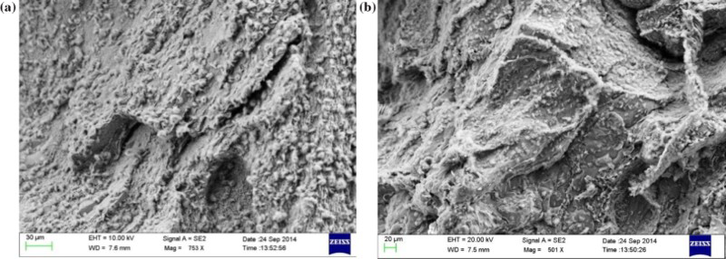
a, b different magnifications of SEM images of tensile fracture specimens produced using taper cylindrical pin profile under condition II
These results coincide with the investigations made by other researchers on friction stir welds including the work carried out by Commin et al.
23
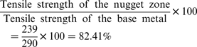
In spite of all these proved facts, 82.41% strength of the base metal can be obtained using the taper cylindrical pin profiled tool along with the ω2/υ ratio equal to the value of 7500 (no. 3-II) as shown below
Distribution of microhardness
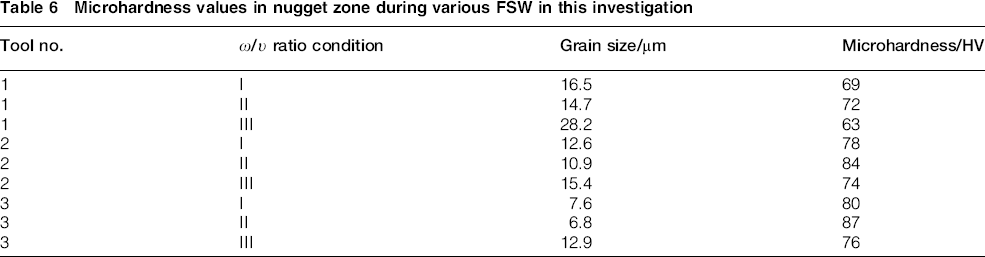
The size of the grain plays an important role in deciding hardness of a welded joint. The slip due to dislocations is restricted by the boundaries of the grain, and hence, the material containing smaller size of grains will have higher values of hardness or greater strength. The hardness values are measured across the weld region, and the values are mentioned in Table 6. From the Table 6, it is evident that the larger the grain size, the lesser the value of the hardness. Thus, when there is a decrease in the grain size, it will lead to a drastic increase in the hardness of the joints. In this way, by producing very fine grain sizes in the NZ compared with that of the base metal, higher values of hardness can be achieved in the NZ.
Microhardness values in nugget zone during various FSW in this investigation
As an example, the values of microhardness of the welded specimens fabricated using the taper cylindrical pin profile under three different conditions of ω/υ ratio are graphically demonstrated in the Fig. 6. Booth et al. 25 discussed that the waviness in the microhardness values as seen in Fig. 6 takes place due to the difference in grain size orientation in the NZ.
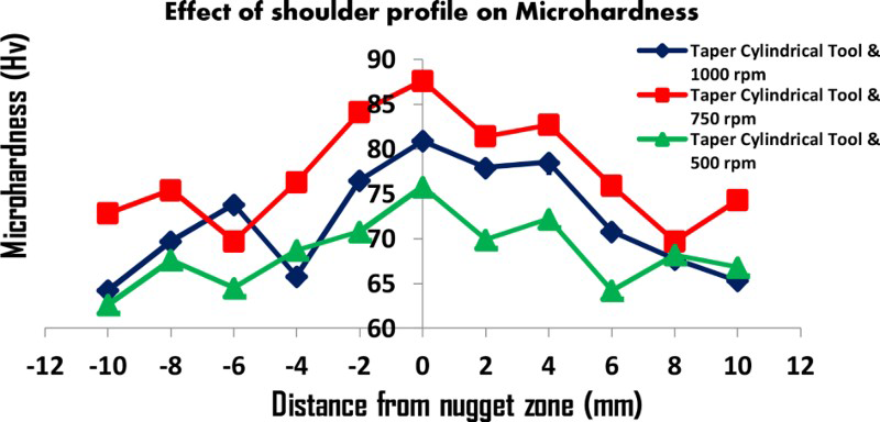
Graphical representation of microhardness values for joints fabricated using FSW under conditions 3-I, 3-II and 3-III
Losses due to wear
The interaction between the tool rotational speed and feedrate on the wear losses of the FSW AZ80A magnesium alloy during the use of three different pin profiles and various ω/υ ratio conditions are shown in Fig. 7. From Fig. 7, it can be observed that the wear losses are minimum at the highest tensile strength values. This can be justified by comparing the values of wear losses in Fig. 7 with the tensile strength values in Table 5. The minimum wear losses were found to be observed during the use of tool 3 and ω/υ ratio condition II. With this same tool pin profile and ω/υ ratio condition, we achieved the highest tensile strength value of 239 MPa. Thus, it can be understood that the minimum wear losses can be produced in the joints under the FSW conditions where highest tensile strength is achieved. It is also evident that the taper cylindrical pin profiled tool produces minimum wear losses during the ω/υ ratio condition II.
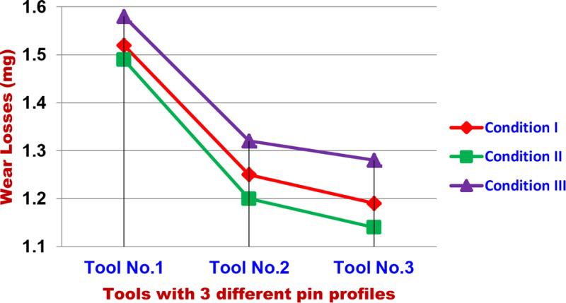
Graphical representation of wear losses (mg) during FSW of AZ80A magnesium alloy using three different pin profiles and various ω/υ ratio conditions
Conclusions
It was evident from the micrographs of the welded joints that the taper cylindrical pin profile, i.e. tool 3, produced a fine grain structure having uniform orientation. Maintaining a constant feedrate and increasing the tool rotational speed made the grains coarser in the NZ, and the grains in the NZ became finer by maintaining tool rotational speed at a constant value with simultaneous increase in the feedrate. Thus, it can be understood that the tool rotational speed plays a more predominant role on the microstructural characteristics and grain size compared with the feedrate. The joints welded using the taper cylindrical pin profiled tool at the ω/υ ratio of 750 rev min− 1 to 75 mm min− 1 under a constant 3 kN axial force value exhibited the maximum tensile strength value of 239 MPa (82.41% of the base metal) compared with other joints. It was noted that the path of the fracture is consistent with the lower hardness distribution profile, and most of the friction stir welded joints are found to undergo fracture at the advancing side where the lowest value of hardness was recorded. The minimum wear losses were experienced in the specimens fabricated using tool 3 and ω/υ ratio condition II.