
Abstract
Friction stir spot welding (FSSW), a solid state welding process, can join materials that are difficult to joint by fusion welding processes. In this study, similar FSSW of lightweight alloy sheets, such as aluminium and magnesium alloys, was performed using tools without thread. The histories of vertical plunge load applied to lapped sheets and the temperature distribution around the stirred surface of the upper positioned sheet during friction stirring were examined. Friction stir spot welding characteristics were discussed regarding the lap shear failure load and fractographic observations after tensile shear tests. A retracted tool produced the highest lap shear failure load for similar aluminium welds, while a pin tool produced the highest lap shear failure load for similar magnesium welds. The failure mode that brought a combination of shear and pullout fracture produced the highest lap shear failure load, which was closely related to the geometry of the tool that developed the enlarged fracture path.
Introduction
In the past few decades, various welding technologies were developed for use in transportation industries to satisfy the demands for improved vehicle performance and fuel economy. For instance, Miller et al. 1 and Kuleckci 2 reported that lightweight alloys (e.g. aluminium and magnesium alloys) were applied to automobile body panels as replacements for conventional steels. Lightweight alloys, Al and Mg alloys in particular, have many advantages: high strength/weight ratio, high thermal and electrical capabilities, excellent sound damping capabilities and they can be used as highly efficient energy saving materials if properly designed.3–6 However, the current welding techniques used in the automobile industry for joining lightweight alloy sheets (e.g. fusion welding techniques) often produce defects, such as cracks, oxide films and cavities, which deteriorate the mechanical property of the joint.4, 7, 8 In regard to these challenges, friction stir spot welding (FSSW), a variant of linear friction stir welding, was developed and tried in the automobile industry because of its capability to join metals below the melting temperature, eliminating potential cracking and porosities after welding.9–13 Friction stir spot welding can also produce sound welds for both similar and dissimilar joints,14–16 and Badarinarayan et al. 17 reported that the FSSW process consumed less energy than fusion welding. Although FSSW is suitable for use with lightweight alloys, the fundamental welding mechanism for various tool geometries should still be understood because of complexity in weld characteristics.
A number of researchers investigated the effects of various welding parameters on the FSSW process. Lin et al. 18 , for example, reported that the strength of FSSW welds depended on the tool rotational speed and holding time, while others tried new and innovative ways, like refill FSSW 19 and heating tool FSSW 20 , to improve the quality of the weld and increase its strength.
Tool geometry, on the other hand, such as the tool pin length, shape and surface patterns, was considered equally important to the welding parameters. Badarinarayan et al. 21 and Uematsu et al. 22 suggested that the tool geometry primarily affected FSSW behaviours. For instance, the effect of tool geometry on microstructure and lap shear strength in FSSW welded Al alloy was reportedly dependent on the tool pin length and diameter.23, 24 Similarly, it was reported that a tool with a scroll surface performed comparably to a conventional pin tool. 25 In addition, large penetration depth can be achieved in a short weld time using profiled tools. 26 Longer holding time, however, might cause a loss of strength because of the progressive hooking behaviour, which was dependent on the tool geometry. In our previous research, we examined the influences of the plunge depth and plunge speed of pin tools on characteristic features after dissimilar FSSW of bulk metallic glass to lightweight alloy.27, 28 In the same manner, the effect of tool geometry on the characteristics of dissimilar FSSW was investigated: the variation of lap shear failure load only existed at smaller tool plunge depth. 29 By selecting the appropriate welding parameters for the adopted tool geometry and material combination, one could achieve optimum weld strength of welded lightweight alloys and a complete metallurgical bonding at the lap joint interface.
In this study, non-threaded pin and pinless tools with specially profiled shoulders were used to characterise the behaviours of the FSSW process using lightweight alloys. The effect of tool geometry on the lap shear failure load, temperature distribution and fracture mode were examined.
Experimental
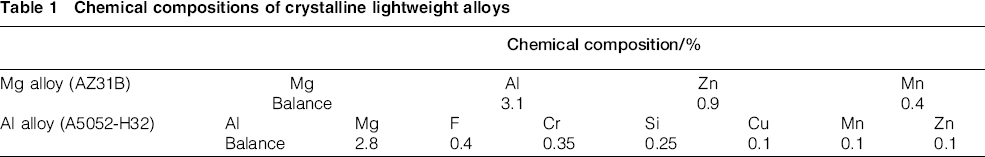
In the FSSW of lightweight alloys, 1 mm thick Al alloy (A5052-H32) and Mg alloy (AZ31B) sheets were supplied. The alloys were fabricated using an extrusion process, and their chemical compositions are shown in Table 1. Each alloy sheet was machined to a coupon shape specimen with dimensions of 100 × 15 mm, as shown in Fig. 1. The FSSW process was performed at the lap joint configuration of the workpieces. The workpieces were fixed firmly by a fixture jig, and the weld spot was located at the central region of the overlapped portion, as shown in Fig. 2.
Chemical compositions of crystalline lightweight alloys
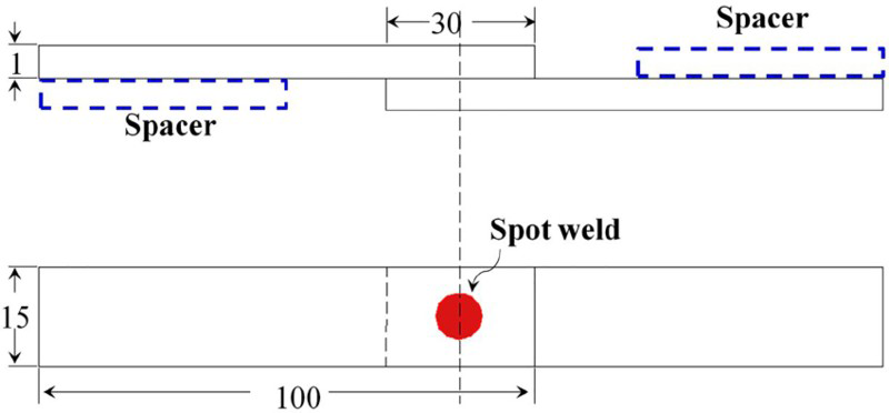
Lap joint configuration of specimen
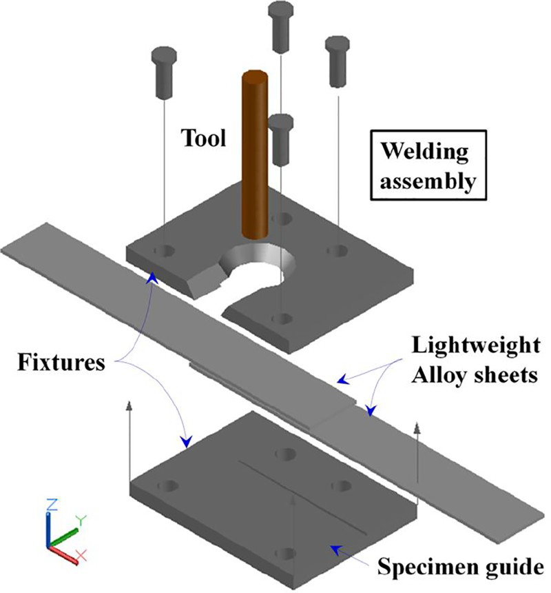
Friction stir spot welding assembly
The FSSW process was carried out in the displacement control mode using a small scale computer numerical controlled milling machine. 30 Using the computer numerical controlled machine, one can control the rotation and plunging speeds of the tool.
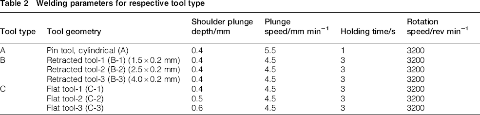
Tool geometries used were divided into three types: pin tool, retracted tool and flat (featureless) tool, as shown in Fig. 3. The pin tool with a cylindrical pin part (2.5 mm in diameter and 1.5 mm in length) was designated as tool A; the pin tool was also composed of a concave shoulder with a 3° angle of concavity. The retracted tools were composed of a 0.2 mm shorten pin, with different diameters of 1.5, 2.5 and 4.0 mm respectively, designated as tool B. The flat tool, designated as tool C, was used to investigate the behaviour of FSSW as the plunge (penetration) depth of the tool increased from 0.4 to 0.6 mm. All tools adopted in this study were made of sintered hard metal with smooth surfaces. There are several reasons why the smooth tools and not the threaded ones were chosen. First, smooth tools can produce welds with a minimum reduction of volume (thickness) at the weld spot. Second, they have a much longer tool life than threaded ones. Last, smooth tools are favourable for use in relatively small machines due to plunging and rotating capacity limitations.
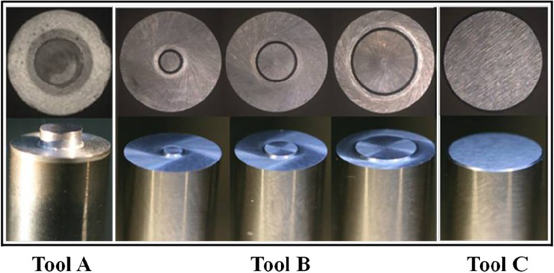
Tool shapes: 1.5 mm longpin tool (tool A), 0.2 mm long retracted tools with different diameters from 1.5 to 4.0 mm (tool B) and flat tool with featureless surface (tool C)
The welding parameters adopted with respect to each tool's geometry are shown in Table 2. The welding parameters for each tool were selected individually through preliminary testing.
Welding parameters for respective tool type
During the FSSW process, the temperature distribution, tool plunge depth and vertically applied load were recorded using devices shown in Fig. 4. The temperature distribution around the weld on the upper positioned sheet was measured using an infrared imager (measurement accuracy, ± 2°C). A laser displacement sensor (sampling rate, 50 kHz) was used to determine the plunge depth. Simultaneously, the vertically applied load to the lap structured specimens during tool plunging was measured using a load cell installed under the specimen fixture jig. Weld strength evaluation for each respective tool geometry and specimen under each test condition was performed using a universal tensile test machine (load cell capacity, 5 kN), at a displacement rate of 2 mm min− 1. Spacers were added at both ends of the lap joint (also shown in Fig. 1) during the tensile test to maintain the alignment. The lap shear failure load corresponding to the peak load on the load–displacement curve was determined. The fractographic morphologies after the tensile shear tests were observed, and the fracture modes were determined using a scanning electron microscope (SEM) and an optical microscope (OM).
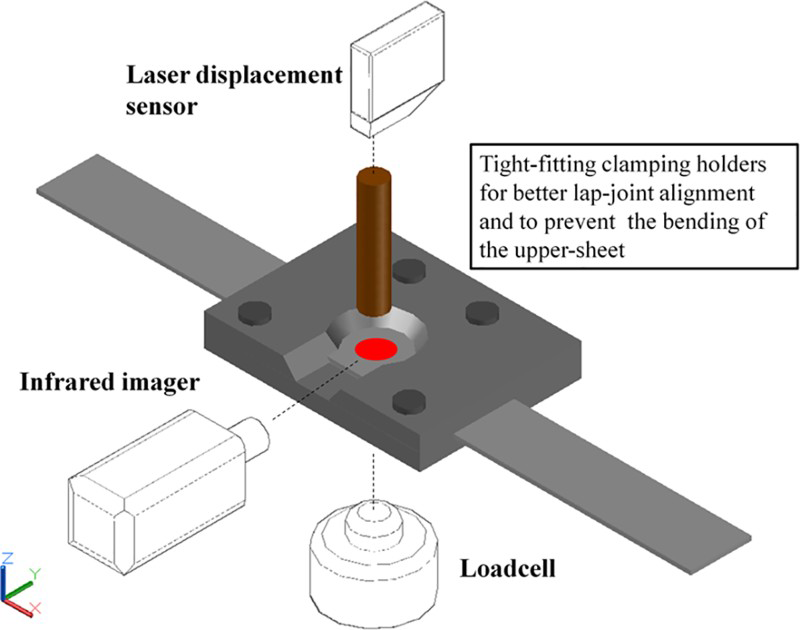
Experimental schematic for measurement of temperature distribution, plunge depth and applied load
Results and discussion
Tensile lap shear test results
Figure 5 shows the load–displacement curves obtained for similar Al and Mg welds. For similar Al welds shown in Fig. 5a, the load–displacement curves yielded different behaviours depending on the tool geometry adopted. In particular, the behaviours after the peak load were related to the fracture mode occurred at the weld spot. The majority of curves after the peak load are noticeably longer, represented by arrows. Identical behaviours were observed for similar Mg welds, shown in Fig. 5b. The load increased almost linearly; however, it failed abruptly after reaching the peak load. This finding reveals that both the peak load and the displacement at failure in similar Mg welds are lower compared to the Al welds.
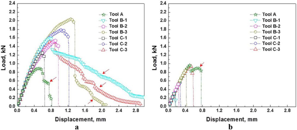
a Al alloy; b Mg alloyLoad–displacement curves obtained by tensile shear tests after similar FSSW of lightweight alloys
Figure 5 also shows the effect of increasing plunge depth on the weld behaviour for tool C. For the Al alloy sheets (Fig. 5a), the lap shear failure load increased upon increasing the tool plunge depth up to 0.5 mm (tool C-2); however, it decreased upon increasing the tool plunge depth to 0.6 mm (tool C-3). Tool C-2 produced a shear fracture at the lapped interface, while tool C-3 produced a pullout fracture, leaving an actual nugget attached on the lower positioned sheet. Cross-sectional observations of the welded part reveal that the reduced thickness of the upper positioned sheet had developed the pullout fracture rather than the complete shear fracture for tool C-3. 31 The reduced thickness under the tool, which is dependent on the tool geometry, controlled the fracture mode under the same welding condition. For the Mg alloy welds shown in Fig. 5b, the load–displacement curves showed almost similar behaviours to the Al welds; however, the generated fracture modes were completely shear fracture for all plunge depths adopted. In addition, tool C-3 produced the highest lap shear failure load.
The peak lap shear failure load results for each tool geometry are plotted in Fig. 6. For similar Al welds, some scattering in the lap shear failure load existed, as indicated by error bars in Fig. 6a. Tool A produced the lowest peak lap shear failure load, while tool B-3 produced the highest peak lap shear failure load among tool geometries adopted, represented by arrows respectively. Although the pin part of tool A penetrated into the lower positioned sheet, the lap shear failure load was relatively lower. This lower lap shear failure load might be the result of insufficient circular flow of materials at the lapped interface, discussed in the authors' study of material flow behaviours. 31 Using tool C, the lap shear failure loads obtained varied with the plunge depth. Additionally, the variance of the error bars was noticeable in the 0.4 mm plunge depth (tool C-1).
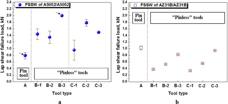
a Al alloy; b Mg alloyTensile shear test results after similar FSSW of lightweight alloys
On the other hand, for similar Mg welds, the peak lap shear failure load for respective tool type was determined and presented in Fig. 6b. Among the tools adopted, tool A produced the highest peak lap shear failure load. A pullout fracture was observed after the tensile shear test. For the retracted tool (tool B), the peak lap shear failure load increased significantly with increased pin diameter. Similarly, the peak lap shear failure load increased with increasing plunge depth, up to 0.6 mm for the flat tool (tool C-3).
Profiles of temperature distribution and vertical applied load
The results of the temperature distribution and the vertically applied load were measured simultaneously for different tool geometries and lightweight alloys during the FSSW process. Figure 7 shows the effect of tool geometry on both the maximum temperature distribution and the vertical plunge load applied with friction time.
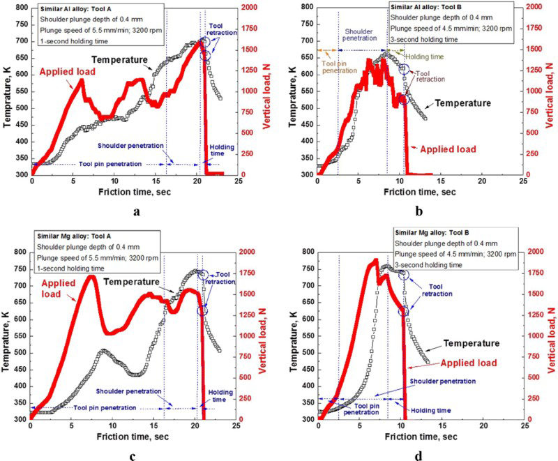
a, b Al alloy; c, d Mg alloyHistories of maximum temperature around friction stirred part and vertical load applied during similar FSSW using pin tool (tool A) and retracted tool (tool B)
For similar Al alloy welds using tool A, the temperature increased gradually and took a longer friction time to reach the peak temperature, as described in Fig. 7a. The peak of applied load was achieved during the tool shoulder penetration. For tool B, however, the temperature curves and the vertical load behaved identically during the friction time, as shown in Fig. 7b. In addition, the pressure exerted from the tool caused a sharp linear increase in vertical applied load until it became saturated during shoulder penetration stage.
Generally, higher temperature and vertical load were generated if similar Mg alloy sheets were used, as shown in Fig. 7c and d. When the pin part of tool A contacted the upper sheet during plunging, it moderates the increase in applied load before the tool shoulder penetration, as described in Fig. 7c. Owing to continuous stirring and plunging, the temperature increased gradually before the tool retraction. Tool A produced the highest lap shear failure load among the tools for similar Mg alloy welds. This curve behaviour result directly represents the importance of tool pin part in generating an appropriate temperature at the early stage of welding using Mg alloy sheets.
High temperature was obtained during the early stage of welding for similar Mg alloy welds using tool B, shown in Fig. 7d. Since Mg alloys have a relatively lower melting range than Al alloys, it is essential to always check the weld for possible liquation or cracking that might degrade the lap shear failure load due to excessive temperature. 32 The curve behaviour result was directly attributed to the mechanical properties of the material adopted. Owing to relatively low elastic modulus of Mg alloy (45 GPa) 33 as compared to Al alloy (70.3 GPa), 34 Mg alloy can absorb deformation energy during plunging elastically. In addition, these findings indicate that the variation in the vertical loads with friction time directly represents the plastic flow and stir behaviours during tool plunging.
Fractographic morphologies
To explain how the fracture mode correlates with the lap shear failure load. The fractographic morphologies after tensile shear test were observed. For tool A and Al alloy sheets, the fracture patterns were dominated by the shear fracture, shown in Fig. 8a. A distinctive weld keyhole is clearly visible at the centre portion of the upper positioned sheet and almost penetrated through the lower positioned sheet. For Mg sheets, however, the resulted fracture mode was a combination of shear and pullout fracture, as shown in Fig. 8b.
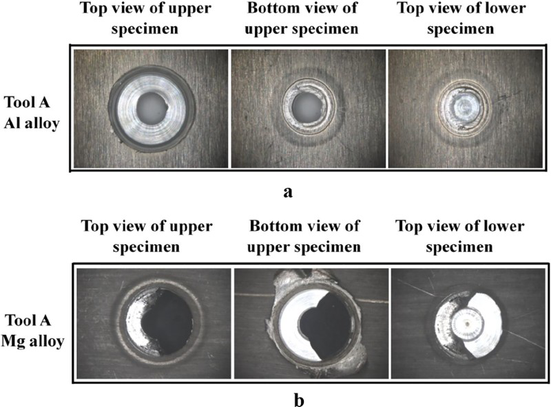
a Al alloy; b Mg alloy weldsFractographic views of similar FSSW using pin tool (tool A)
Figure 9a shows the fractographic views of similar Al alloy welds using pinless tools (tools B and C). Depending on the tool geometry, three distinctive fracture modes were observed: a shear fracture at lap joint interface (tool C-1), a combined shear and pullout fracture (tool B-3) and a complete pullout fracture (tool C-3). Their schematic cross-sectional views are described in Fig. 9b. The fracture path is indicated by a thick dotted line, and the remaining section above the original interface (indicated by the thick solid line) represents the nugget developed on the cross-section of the lapped joint.
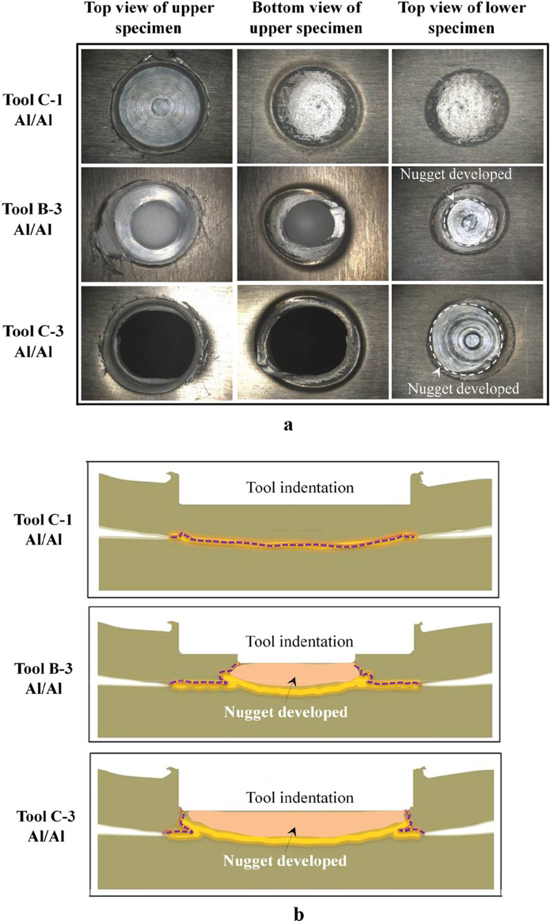
a fractographic views of similar Al alloy welds produced by pinless tools (tools B and C) and b corresponding schematic cross-sections
When tool C-1 was used, the fracture paths observed were relatively longer than with the tools B-3 and C-3; however, it was dominantly governed by the shear fracture at the original lapped interface. Furthermore, there was no actual nugget developed at the stirred spot, as described in the fracture images of faying surfaces in Fig. 9a. For tool B-3, this tool consistently produced the highest lap shear failure load and a combination of shear and pullout fracture, leaving a nugget at the stirred spot. The nugget size, which is almost the same as the diameter of the retracted pin, was developed at the centre of the spot weld. The fracture path that passed through the perimeter of the nugget and the additional bonded area surrounding the nugget produced the highest lap shear failure load.
For tool C-3, a complete pullout fracture occurred along the perimeter of the developed nugget. The nugget size for tool C-3 was larger than the nugget developed by tool B-3; however, the results of lap shear failure load for tool C-3 were lower than those of tool B-3. This result is attributed to the comparably shorter fracture path observed for tool C-3, which was represented by the thick dotted line in Fig. 9b. The observations suggested that aside from the fracture mode, the plunge depth that generated the enlarged fracture path is also important. These findings reveal that the tool geometry significantly influences the behaviour of the FSSW welds in two ways: the fracture mode and the length of fracture path.
For similar Mg alloy welds using pinless tools (tools B and C), only shear fracture at the joint interface was observed. A relatively low lap shear failure load was obtained, and no actual nuggets developed; however, traces of tool rotation effect extend to the boundary between both sheets were observed, as described by the images of lower positioned sheets in Fig. 10. In addition, as the interface welded area increases, the interface surface texture changed from course to fine, as can be seen in the magnified views of Fig. 10.
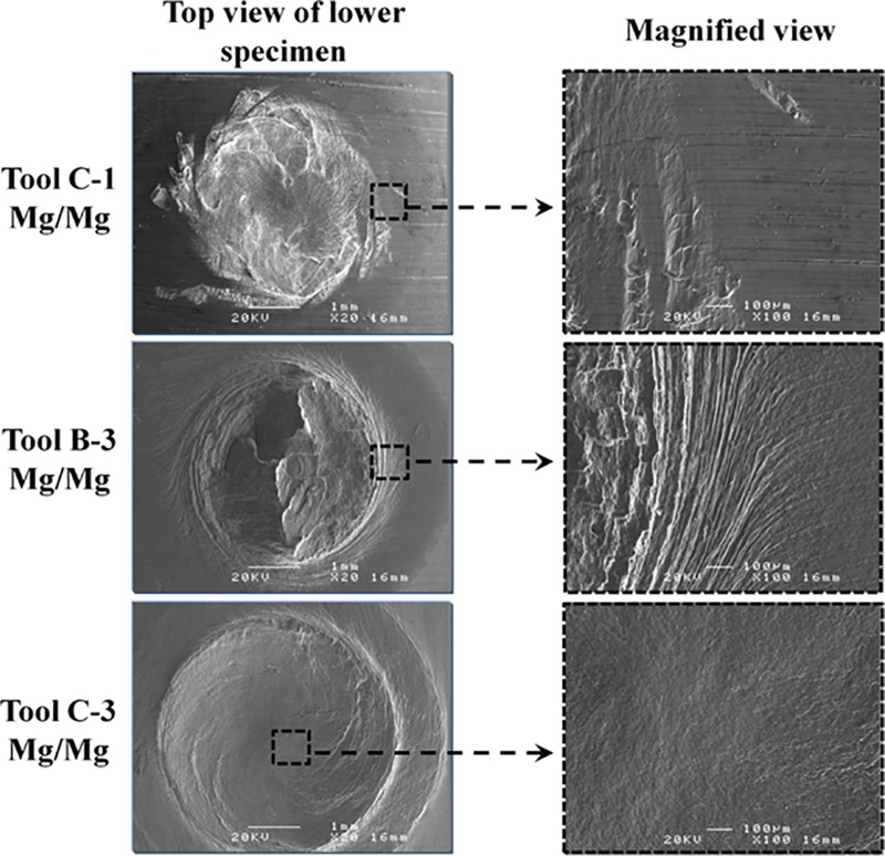
Morphologies of fracture surface on lower positioned sheet for similar Mg alloy welds using pinless tools (tools B and C)
The FSSW process using pinless tools, especially profiled shoulder tools, is expected to make lightweight alloys applicable to the automobile industry. The results suggest that the behaviours of similar lightweight alloy welds using FSSW depend on the tool geometry adopted; however, in order to achieve good weld strength comparable to steels, further investigations considering the balance of tool geometry and welding parameters are still needed. In addition, by introducing the stepped retracted pin part with varying pin length and diameter, the potential formation of enlarged fracture surface or fracture path is possible.
Conclusions
The FSSW of lightweight alloys using various tool geometries was performed. For similar Al alloy welds, a retracted tool developed the largest fracture path and produced the highest lap shear failure load among the tools adopted. For similar Mg alloy welds, the pin tool produced the highest lap shear failure load, although it brought a slightly lower lap shear failure load than the Al alloy welds. Based on the fracture morphologies, the fracture paths varied depending on the tool geometry adopted. The fracture modes were characterised into three: shear fracture at lap joint interface, complete pullout fracture and a combination of shear and pullout fracture, in which the latter case developed the enlarged crack path and produced the highest lap shear failure load.
Footnotes
Acknowledgements
This work was supported by a grant from National Research Foundation of Korea (grant no. NRF-2014-002640) and the BK21 plus funded by the Ministry of Science, ICT and Future Planning (MSIP), Republic of Korea.