
Abstract
A tandem gas metal arc welding system was utilised for narrow gap welding in vertical down position. In the welding process, the two pulses are asynchronous and two arcs worked in the same molten pool. The molten pool forming process was investigated, and the results suggest that an asymmetric pool was generated, which resulted in the asymmetry of the weld bead. This condition could be improved by decreasing the distance between the two wires. The forces acting on the molten pool and the droplet were analysed. It is pointed out that, in vertical welding with low welding speed, more fusion metal flows down to the head of the molten pool due to the gravity, which leads to the reduction of the penetration depth. Based on the results, a multilayer welding was conducted with a high welding speed and a close distance between two wires, and a high quality weld was acquired.
Introduction
Thick walled plates are widely used in the ship building industry, pressure vessel and pipeline engineering. The conventional welding processes in use today, such as submerged arc welding, require longer welding times and more filler metal, and result in greater weld distortion. Butt welding of thick walled plates with narrow gap (NG) instead of conventional U groove and V bevel angles is recognised as one approach to reducing the time and cost of welding. It has many advantages such as high productivity, high quality, minimal distortion and all position capability. However, incomplete sidewall fusion is the most frequent defect in NG gas metal arc welding (NG-GMAW), so the objective of NG welding is to maintain uniform and sufficient penetration at both groove faces.1–3
Several methods such as rotating arc,4–7 oscillating arc8, 9 and tandem GMAW 10 were developed to ensure the sufficient penetration of sidewall in NG-GMAW. However, the systems of rotating arc and oscillating arc NG-GMAW are relatively complex. Narrow gap welding and tandem GMAW are both high efficient welding methods, so tandem NG-GMAW, which combines the advantages of the two methods, has potential applications.
A better understanding of the molten pool behaviour involved in the GMAW process is imperative and useful for precise control of the geometry and quality of the weld bead. However, the molten pool behaviour of tandem NG welding were rarely reported. In this study, a tandem GMAW system was applied for NG welding. The end of the contact tips were bent to direct the arcs toward opposite sidewalls to increase the sidewall penetration. The two arcs worked in the same molten pool due to the close distance between the two wires along the welding direction. A vertical down welding process was carried out, and the molten pool behaviour was observed, and the weld forming mechanism was revealed by analysing the forces acting on the molten pool. Based on the results, the appropriate welding conditions were selected, and a sound weld was acquired. The present work promotes the application of tandem NG-GMAW in all position welding.
Experimental apparatus and materials
The schematic of the experimental apparatus are presented (Fig. 1). The two wires are fed through two electrically isolated contact tips into the molten pool. The wires can be controlled independently by two CLOOS 503 power sources. The power sources are operated in pulsed mode in which the peak voltage and the base current are constant, and the pulsed currents are asynchronous to minimise the arc blow.
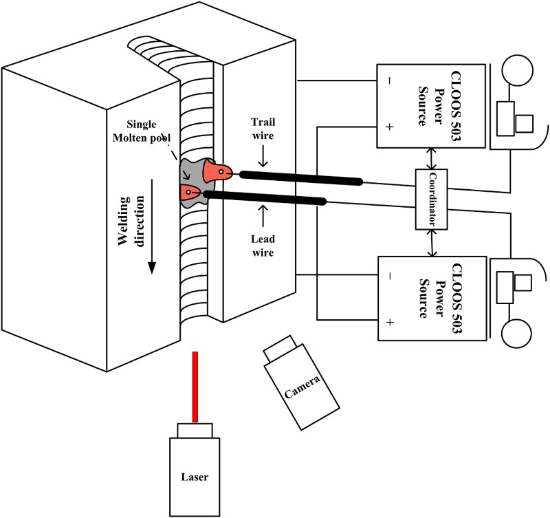
Schematic of experimental apparatus
The torch is shown in Fig. 2. The end of the two contact tips are bent to direct the two wires toward the opposite sidewalls to ensure the sufficient sidewall penetration, and the bending angle is 7°. The U groove with a bottom width of 10 mm, top width of 12 mm and depth of 25 mm is applied. A CamRecord 5000 × 2 high speed video camera (2000 frames/s) is used to observe the molten pool behaviour. A laser illuminator is used as a light source, and a band pass filter with the wavelength of 808 ± 10 nm was used.
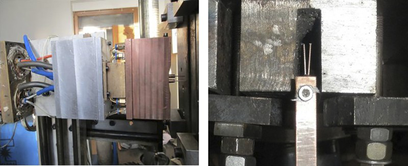
Torch of tandem NG GMAW
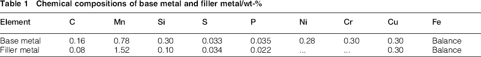
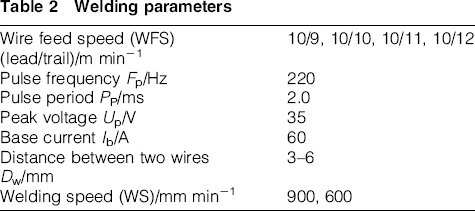
Q235 and H08Mn2Si are used as base metal and filler metal respectively. The chemical compositions of base and filler metals are shown in Table 1. The diameter of the wire is 1.2 mm. As shielding gas, 92%Ar+8%CO2 with a flowrate of 40 L min− 1 is used. The parameters used during the welding process are given in Table 2.
Chemical compositions of base metal and filler metal/wt-%
Welding parameters
Results and discussion
Molten pool forming process
The high speed images of the molten pool forming process are shown in Fig. 3. The left wire is trail wire, and the right wire is lead wire. In the welding process, after striking the arcs, the bottom of the groove is heated and melted; then, two independent molten pools with a small size are generated (t = 239.0 ms). The wires melt and the droplets transfer into the molten pool continuously, and the size of each molten pool increases. The molten pool under the trail wire began to flow down due to the gravity, and a ‘metal stream’ appears between the two molten pools (t = 342.5 ms). With the further increase in the two molten pools, the fusion metal in the trail pool flows into the lead pool, and the ‘metal stream’ broadens until its width is similar to the pools' (t = 354.5 ms, t = 376.5 ms and t = 412.0 ms). Then, the two independent molten pools connect with each other and become a single molten pool (t = 845.5 ms). The schematic of this process are presented in Fig. 4.
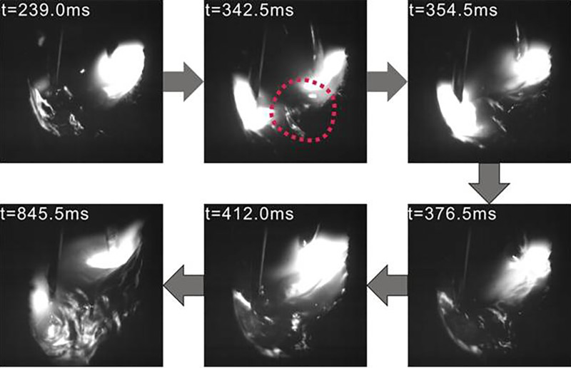
High speed images of molten pool forming process
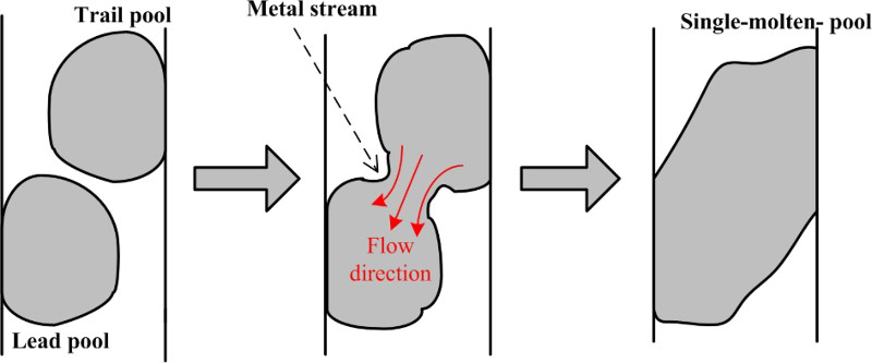
Schematic of single molten pool forming process
Asymmetry of molten pool
The arrangement of the two wires and the bend of the contact tips lead to the asymmetry molten pool. When the Dw exceeded 6 mm, the molten pool became extremely asymmetric, which results in the asymmetry of the weld. Figure 5 suggests the asymmetry of the molten pool (Dw = 6 mm). The longitudinal length of the molten pool became longer due to the longer Dw. At the beginning of the generation of the molten pool, it is asymmetric (t = 431.0 ms). The droplets transfer into the molten pool, and the solidification rate of the fusion metal is slower than the melting rate of the welding materials. The molten pool increases and more fusion metal flows to the side of the lead wire, and the distance between the end of the lead wire and the molten pool surface becomes closer (837–1323 ms). The shape of the molten stays the same when the solidification rate of the molten metal is equal to the melting rate of the welding materials, and an extremely asymmetric pool is created (t = 1751.5 ms).
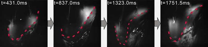
Asymmetry of single molten pool
As shown in Fig. 6, the weld appearance is good when the Dw is 4 mm. On the side of the lead wire, more fusion metal is between the arc and the base metal, so the depth of sidewall penetration of this side is shallower than the other side because of the cushion effect. 11 The asymmetry decreases when the Dw is at low level (3–5 mm), but it cannot be eliminated. The Dw is set to 4 mm in the subsequent trials.
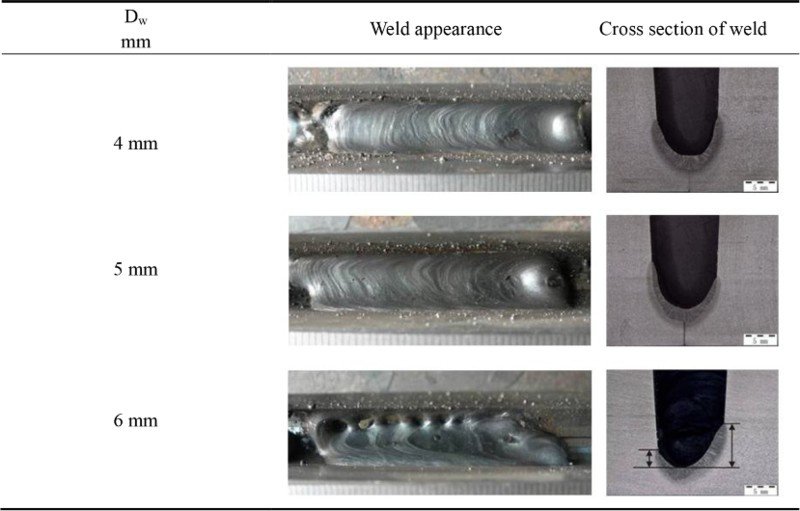
Weld shape with different Dw
In order to eliminate the asymmetry of the weld, the different wire feed speeds on each wire were investigated. As shown in Fig. 7, when the WFS of trail wire is higher than that of the lead wire, the arc pressure of the trial arc on the molten pool is strong, and more fusion metal flows into the lead pool, so the weld is obviously asymmetry. If the WFS of lead is slightly higher than that of the trail wire, the weld tend to be symmetric, but it is not improved evidently. Thus, the Dw has a more obvious effect on the asymmetry, and the wire feed speeds on each wire are set to the same.
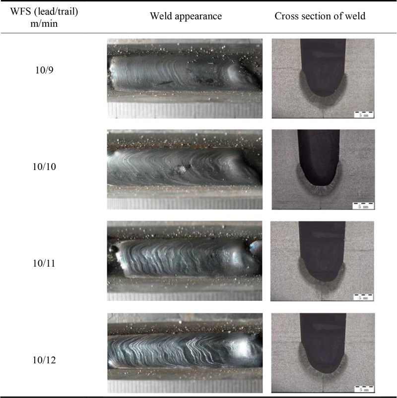
Weld shape with different WFSs on each wire
Weld forming mechanism
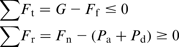
Weld formation has a relationship with the molten pool behaviour, and the molten pool behaviour depends on the forces acting on it. The two pulses are asynchronous, so the interaction between the two arcs was minimised and it can be ignored. Additional, the two wires are close, and when one current is at peak, the other one is at base, and only one wire transfers into the pool, so the twin wires model can be simplified to single wire model in the following analyses. As shown in Fig. 8, the molten pool has the following forces on it: arc pressure force Pa, droplet impact Pd, support force by the based metal Fn, the interfacial tension Ff and gravity G. These forces should satisfy formula (1) to avoid the sag of the molten pool
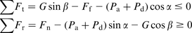
Schematic of force affecting molten pool
If α < 90°, then cos α>0 and (Pa
+ Pd) cos α>0, so the tangential component force of (Pa+Pd) can partly offset the tangential component force of G, and the molten pool tends to keep balance. Thus, it is better to incline the torch; however, in tandem NG welding, in order to keep the parameters of the two arcs similar, α is set to 90°. In vertical welding, β is 90°. Thus, formula (1) can be simplified to formula (2)

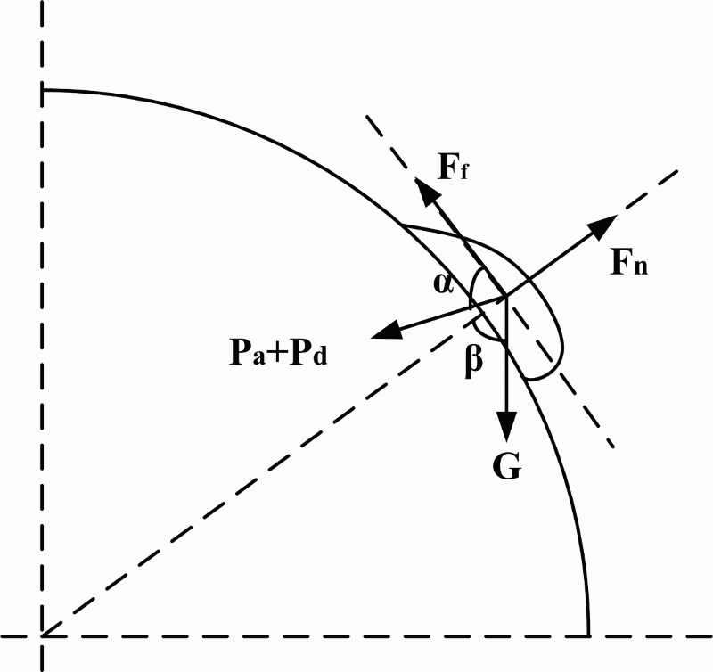
As shown in Fig. 9, because of the effect of the gravity, the actual forces affecting the droplet and molten pool are presented. In pulse base, the electromagnetic force and plasma flow force are low, and the droplet tends to fall due to the gravity. The droplet grows with the wire melting, and the effect of gravity strengthen. While in pulse peak, the current rises sharply, and the electromagnetic force and plasma flow force become large; the droplet detaches from the end of the wire and transfers into the molten pool. The travel path of the droplet deviates the axis of the wire. The fusion metal flows down because of the gravity, and the vertical component force of the droplet impact also aggravates the sag of the molten pool. Pa and Pd act on the surface of the molten pool but not directly on the base metal. More fusion metal flows to the head of the molten pool, which acts as a cushioning effect in reducing depth of penetration. 11
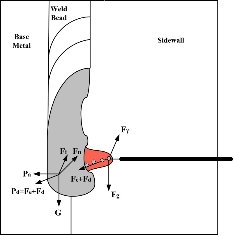
Schematic of actual forces acting on droplet and molten pool
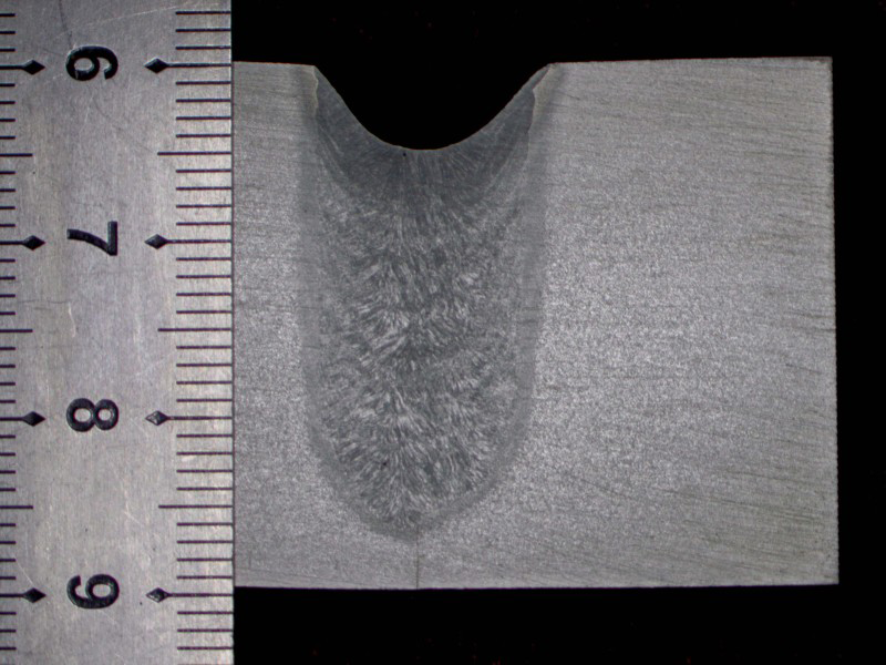
The solidification rate of the molten pool is high, so the weld shape of the position where the arc extinguishes can approximately represent the molten pool shape. The weld longitudinal section is shown in Fig. 10 (WFS = 600 mm min− 1). It can be found that the deposited metal layer at the arc extinguishing position is thick, and the metal has the trend to flow down. The thickness of the weld is similar to that of the arc extinguishing position, and it indicates that the more molten metal does not flow to the tail of the molten pool but tends to flow to the head of the arc. The experimental result coincides with the analysis.
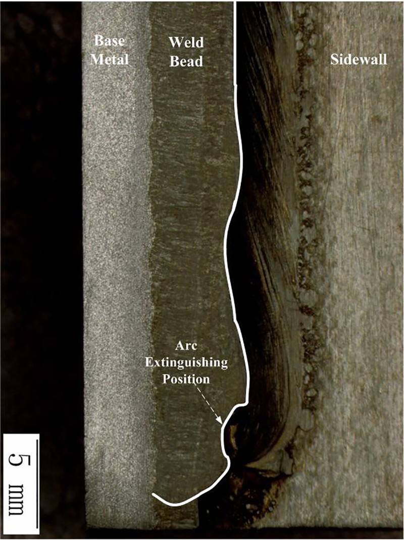
Weld longitudinal section
Because of the negative effect of gravity, in order to hinder the fusion metal from flowing down and ensure the sufficient penetration depth, a high welding speed should be selected in vertical welding process. An appropriate heat input should be obtained to achieve a small molten pool and more rapid solidification rate.
Single pass multilayer welding
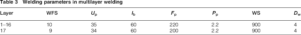
Based on the above results, a single pass multilayer butt welding process is carried out. Each layer is made of one bead. The parameters are given in Table 3.
Welding parameters in multilayer welding
The weld appearance of different layers are shown in Fig. 11. It is obvious that the weld appearance is good. Figure 12 shows a cross-section of the multilayer weld. A stable uniform penetration into the sidewall is obtained, and the weld is almost symmetric without defect.
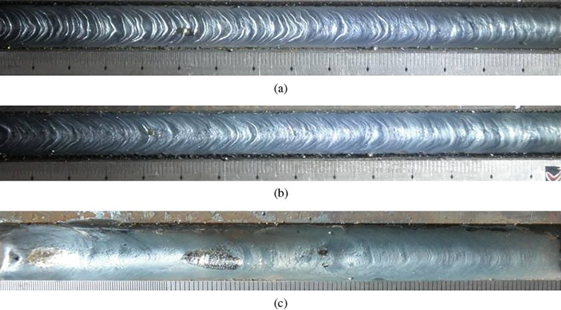
a first layer; b third layer; c seventeenth layerWeld appearance of different layers
Cross-section of multilayer weld
Conclusions
In vertical welding, more metal deposited on the side of lead wire, so the molten pool and the weld bead are asymmetric. The asymmetry can be improved by decreasing the distance between two wires. In vertical welding with low welding speed, more fusion metal flow down to the head of the molten pool due to the gravity, which acts as a cushioning effect in reducing the penetration depth. A high quality multilayer weld can be acquired with a high welding speed and a close distance between two wires.
Footnotes
Acknowledgement
We are grateful to the National Natural Science Foundation of China (grant no. 51275109) for the financial support to this study.