
Abstract
Owing to the rapid cooling rates, the deposited and base metals could be mixed incompletely during laser welding of Al alloys in most cases. The objective of this research is to explore a possible method to promote the mixing of materials inside the molten pool by making use of the magnetofluid dynamic effect of electric current. Full penetration CO2 laser welding of 3 mm thick alloy 6009 sheets was performed with an external electric current simultaneously into the weld pool via a filler wire. It is found that the deposited metal is mainly concentrated on the upper part of the weld fusion zone, and the weld zone microstructure is non-uniform without the electric current addition. With the application of an electric current, the weld fusion zone geometry is reshaped, and the chemical composition and microstructure of the weld metal are homogenised. The mechanism is found to be electromagnetic force stirring of the molten pool.
Keywords
Introduction
Aluminium alloys have many specific properties including lower densities, higher specific strengths and better corrosion resistances, which have been increasingly applied to various lightweight structures in aircrafts, automobiles, rail vehicles and ship building industries.1, 2 Laser beam welding has been considered as one of the most important joining methods for aluminium alloys due to the high energy density and rapid welding speeds. 3 Joints can be obtained with fine solidified microstructures, narrow heat affected zones and excellent mechanical properties in laser beam welding.3–5 However, there are a number of weldability issues and problems associated with aluminium alloys in laser beam welding such as defect formations (i.e. porosity and hot cracking), non-uniform microstructure and compositions, process instability and weld fusion zone geometry related degradation.4, 5
In order to improve the weld qualities, many new developments in introducing an additional energy field combined with laser welding processes have been exploited in recent years. One of the important applications is to use magnetic and electric fields. Kern et al. reported that an intrinsic electric current was found in the CO2 laser welding pool, without externally applying an electrical power to it. 6 Ambrosy et al. further confirmed that the intrinsic electric current was generated by the laser induced plasma in the CO2 laser (10.6 μm wavelength) welding. 7 For shorter laser wavelengths, the laser induced plasmas are much weaker in, for example, Nd:YAG (1.06 μm wavelength) and fibre laser (1.07 μm wavelength) welding, due to low plasma absorption of laser beams.8, 9 Therefore, the intrinsic electric current is mainly present in the CO2 laser welding. By applying an external magnetic field, the reshaped weld cross-sections,6, 7 improved process stability 6 and material dilutions can be achieved,10, 11 but there is no significant effect in Nd:YAG laser welding. 12 Avilov et al. reported 30 mm full penetration fibre laser butt welds of aluminium alloy plates, which is mainly attributed to the application of an electromagnetic field to support the weld pool against gravity.13, 14 Xiao et al. proposed the application of an electric current to influence the melt flow via an additional electrode or through the filler wire in the front part of the molten pool.15–17 The self-induced magnetic field of the current can be produced to affect the melt flow resulting in the significant improvements in the welding process stability and efficiency both in CO2 laser welding and in Nd:YAG laser welding. Although the application of an electric current to the weld zone was reported before, their stirring effects on the microstructure and chemical composition in the weld pools were not considered.
Filler materials are commonly used in laser beam welding of aluminium alloys for several reasons. In general, the filler metals have been introduced into the weld pool to compensate for the alloying elements vaporised, to prevent solidification cracking or to satisfy requirements of certain joint performances.3, 5, 18 Owing to the high depth/width aspect ratio of the welding pool, as well as the rapid heating and cooling rate, the fluid flow and the limited diffusion in the molten pool often result in the inhomogeneity of alloying element distribution. Therefore, the homogeneous dilution of the base metal and the filler material cannot be guaranteed in the weld joints. 19
In this study, an electric current via the filler wire was introduced into the molten pool during CO2 laser welding of 6009 aluminium alloy sheets, for the first time, and the effects of the electric current on the weld formation, alloying element distribution and microstructure over the weld have been investigated.
Experimental conditions and procedure
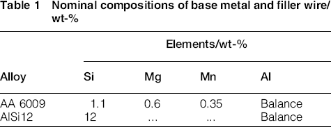
Figure 1 shows the schematic illustration of the in situ electric current supported laser beam welding process configuration. Bead on plate welds on AA 6009 aluminium alloy sheets with a dimension of 250 × 100 × 3 mm were produced using a TRUMPF continuous wave CO2 laser. The electric current was introduced to the welding pool via the forward feeding filler wire along the welding direction. The wire was AlSi12 with a diameter of 1.2 mm. The nominal compositions of the base metal and filler wire are listed in Table 1. The focus number of the welding head was 3.7, yielding a focus diameter of 0.3 mm. The focus position was set on the workpiece surface. The welding was operated at a 3 kW of the laser power, a 3 m min− 1 of the welding speed and a 3 m min− 1 of the wire feedrate. Helium shielding gas at a flowrate of 25 L min− 1 was supplied by an off-axis nozzle with a diameter of 6 mm to suppress the laser induced plasma and to protect the welding pool from the atmosphere. The nozzle was positioned at a distance of ∼3.5 mm from the laser beam at an angle of 30°. The above welding parameters were derived from numerous initial experimental studies to achieve full penetrated welds with good formation and no cracks. The electric current was varied from 0 to 200 A with 50 A increments. For the ease of description, the 0 A was defined as welding without current addition.
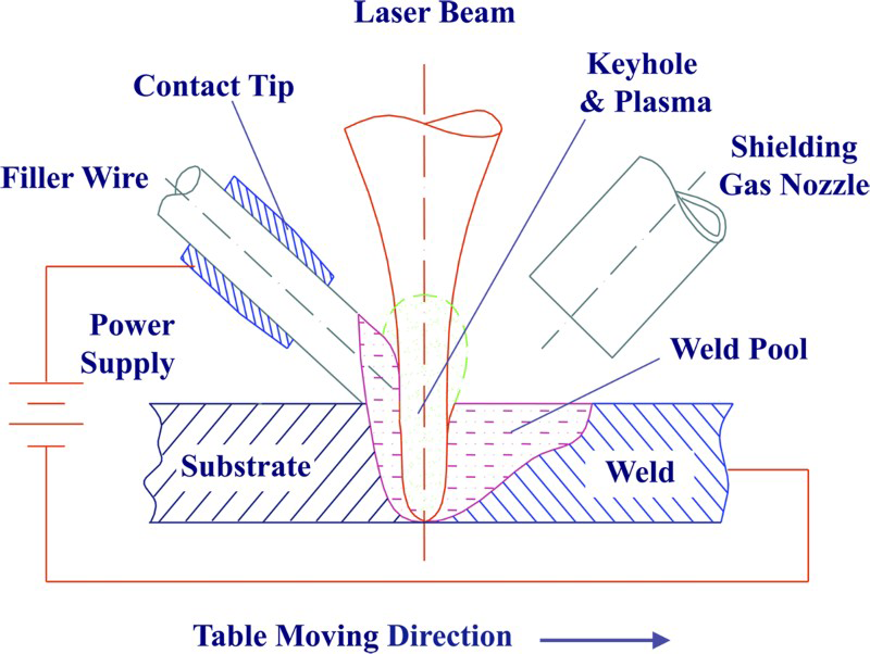
Scheme of experimental set-up for electric current stir laser welding
Nominal compositions of base metal and filler wire/wt-%
After welding, cross-sections were grinded and etched with Keller's reagent for 60 s at room temperature. The weld profiles were observed using optical microscopy. Owing to the large difference of silicon contents in the base metal and the filler wire, silicon was taken as the tracking element, and its distribution in the weld was analysed by scanning electron microscope (SEM) equipped with energy dispersive X-ray spectroscopy. Microstructures were examined using SEM. Microhardness measurement was performed at a load of 100 g for 15 s.
Results
Weld profiles
Figure 2 shows the weld formations under different currents. A few pores were occasionally observed, regardless of the application of the electric current. The weld fusion zone was a wine glass shape when welding without the current addition. In contrast, the fusion zone shape changed to a reversed wine glass shape when a current of 200 A was applied. Figure 3 summarises the effects of the electric current on the weld widths and area. The welding was repeated three times for every combination of parameters, and three cross-sections were made for each bead. It is obvious that the top weld width decreases and the bottom width increases with increasing the current. However, the fusion zone cross-section area almost remains the same under different current conditions. Further experiments showed that changing the electric power polarity had no influence on the profiles.
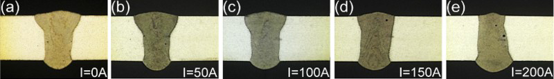
a I = 0 A; b I = 50 A; c I = 100 A; d I = 150 A; e I = 200 AWeld formations with external current under different amperages
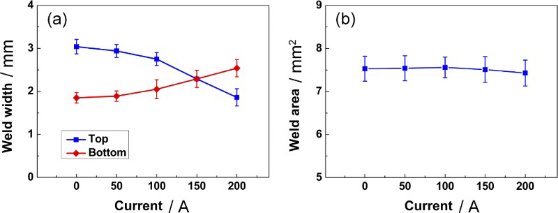
Relationships between weld fusion zone a widths and b area with current
The weld fusion zone cross-sections demonstrated roughly three kinds of shape on the basis of optical observations under different applied currents. When welding without the electric current or with a lower current ( < 100 A), the weld was in a wine glass shape and the top weld width was greater than that at the bottom. As the current was increased up to 150 A, the top and bottom weld widths were nearly the same. Further increasing the current to 200 A resulted in the bottom weld width greater than the top weld width.
Element distribution
Owing to the large differences of the silicon contents in the base metal and the filler wire, the silicon distribution in the weld represents the degree of mixing the deposited metal with the base metal. Figure 4 shows the silicon mapping in a weld zone, and Fig. 5 demonstrates the line scanning plots of the silicon element in the welds when welding without current and with a current of 150 A. In Fig. 5 inserts, the line scanning was performed along two mutually perpendicular lines across the joints, and the dash lines represent the fusion boundaries of the welds. The distribution of silicon is inhomogeneous at the macroscale over the whole weld when welding without an electric current addition, indicating that the deposited metal and the base metal have not mixed well. The deposited metal, deduced from the silicon distribution, is significantly enriched in the upper region of the weld and mainly in the areas beside the fusion boundaries. However, there is a quite uniform distribution of the silicon within the weld when welding with an electric current of 150 A, demonstrating that the deposited metal and the base metal have mixed each other completely in the welding pool.
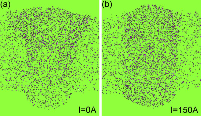
Distribution maps of silicon throughout weld at a 0 A and b 150 A
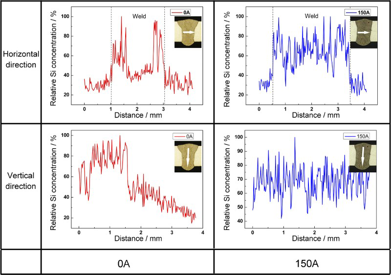
Line scanning plots showing silicon distributions under 0 and 150 A current conditions (dashes representing fusion boundaries), showing vertical and horizontal concentration profiles across cross-sectional joints
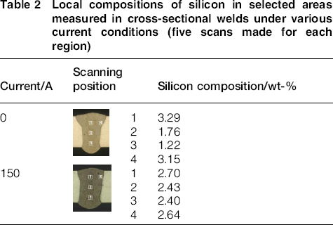
Further investigations on the deposited metal distribution in the local regions were quantitatively performed. The results are presented in Table 2. The inserts show the four regions with an area of 50 × 50 μm for each weld. The local composition of silicon varied in the weld without current, decreasing from 3.2 wt-% at the top to ∼1.2 wt-% at the bottom along the weld centreline. When welding with a current of 150 A, it is obvious that the silicon concentration is homogeneously distributed in the whole weld, having ∼2.5 wt-% on average.
Local compositions of silicon in selected areas measured in cross-sectional welds under various current conditions (five scans made for each region)
Microstructure and microhardness
The SEM examination reveals the dendritic solidification structures in the fusion zones, as shown in Fig. 6. The phases in the interdendritic regions exhibit relatively a brighter contrast in Fig. 6 after chemical etching, partitioning the α-Al matrix lacking in the precipitates. Beside the interdendritic and grain boundaries are significant amounts of the alloying elements, such as silicon, magnesium and manganese as well as the impurity element iron. The solute redistribution occurs resulting in the segregation of alloying elements as a consequence of non-equilibrium solidification; thus, the second phase particles or eutectic phases will form around the interdendritic regions. 20 Comparing Fig. 6a and b, the interdendritic and intergranular phases form in non-uniform distribution over the depth of the weld without current addition. In contrast, with the addition of 150 A current, the fusion zone microstructure is relatively uniform in terms of grain size and alloying element distributions over the weld, as seen Fig.6c and d.
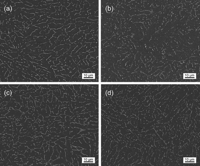
Images (SEM) for etched cross-sectional along weld centreline in 0 A weld at a top and b bottom, and 150 A weld at c top and d bottom
Figure 7 shows the microhardness distributions along the weld centrelines from the top to bottom. A slight difference in hardness occurred without the electric current, while the hardness distribution was changed relatively steadily with small fluctuation along the weld centreline after applying the current.
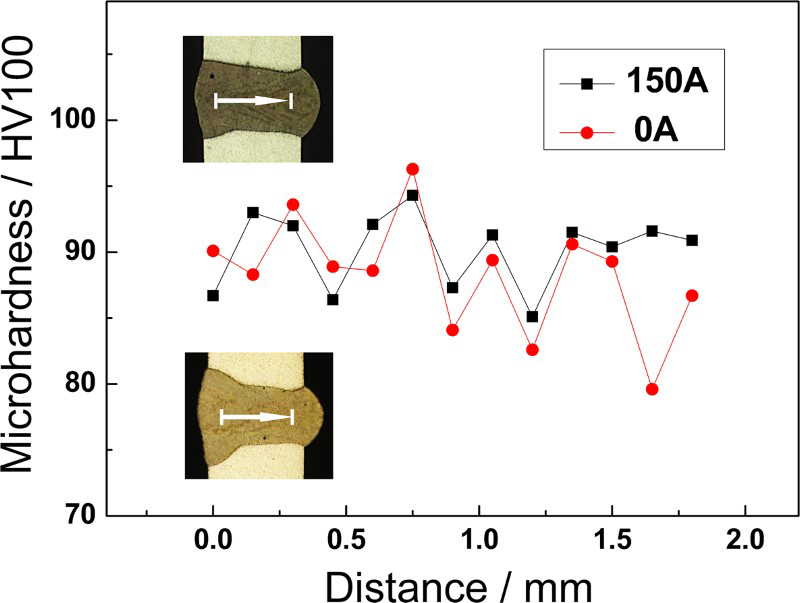
Microhardness profiles of welds with and without current; inserts show measuring paths and regions
Discussion
In laser keyhole welding, heat and material transports occur primarily by convection, whereas heat conduction and element diffusion in the weld pool is not so important. The complex flows occur within the molten pool due to the complication of laser welding process, as compared to conventional welding technology. The dynamic behaviour of the molten pool in laser keyhole welding is summarised as shown in Fig. 8.21, 22 It shows that the metal flow moves downward along the front keyhole wall and then to the rear part of the weld pool surrounding the keyhole, while the flow around the keyhole is also stretched towards the pool boundary at the weld pool surface. As a result, the typical wine glass shape of the weld cross-section tends to be formed, as shown in Fig. 2a. On the other hand, the melt flow promotes the mixture of the deposited metal and the base metal in the molten pool. However, there is insufficient time for the complete mixture due to the rapid heating and cooling rate, as well as the narrow width and great depth of the welding pool. In this study, the enrichment of the deposited metal in the upper region and beside the top fusion boundaries occurs, as a result of the weld pool dynamics, which to some extent confirms the previous studies.21, 22
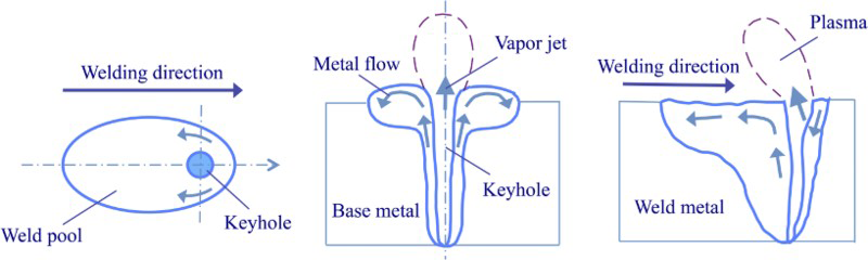
Schematic illustrations of flow phenomena in molten pool in deep penetration laser beam welding from a top and b, c side views
When an additional electric current is applied, a self-induced azimuthal magnetic field, which is proportional to the current density, generates in the weld pool, resulting in electromagnetic volume forces proportional to the square of the current density. 15 Owing to the divergence of the current lines from the wire tip to the workpiece, the current density distribution is not uniform in the weld pool. The current density close to the wire tip and the keyhole front is higher than that at the bottom and the rear of the welding pool, as illustrated in Fig. 9. Therefore, the electromagnetic volume forces are much greater at the top surface in front of the keyhole in the welding pool. Accordingly, the molten metal in front of the keyhole is accelerated towards the bottom, which brings heat and the deposited metal. Because a larger quantity of material at the bottom is heated and melted, the weld shape is consequently changed. Moreover, the deposited metal is brought downward, implying the presence of the enhanced mixing in the weld pool, resulting in the increased amount of the alloying elements at the bottom. Since the electromagnetic force is only determined by the current density and is independent on the current direction, changing the electric power polarity has no influence on the weld pool dynamics. 15 Furthermore, the thermal effect of the current is negligible. Although the electric current is large, the electric resistance is negligibly small. By calculating, the estimated additional electric power is ∼40 W at the current of 200 A, which is less than the fluctuation amplitude of the laser power. This conclusion can also be derived from the fact that the current addition has seldom influenced over the weld cross-section area.
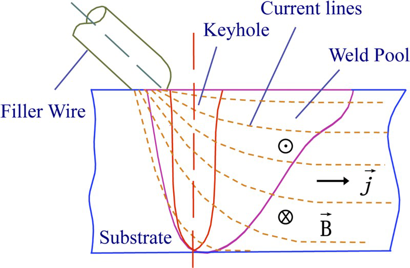
Schematic diagram of current density distribution in weld pool
In general, the fusion zone microstructures are mainly related to the alloying element composition and the cooling condition during solidification. The issues of the deposited metal distribution have been mentioned above, while the weld fusion zone shape is formed according to the liquid convection and cooling condition as a result of dissipation of heat away from the weld pool to the sheets. The weld geometry is characterised with a larger weld width and hemispherical shape near the top surface without current, implying that the heat input in the upper region of the weld is greater than that in the lower part (see Fig. 2a). In addition to the cooling rates, the different local contents of the deposited metal lead to the significantly inhomogeneous microstructures over the solidified weld. After the addition of the current of 150 A, the weld shape became uniform (see Fig. 2d), which reveals that the cooling conditions are similar between the top and the bottom of the weld. The uniform distribution of the alloying elements and similar cooling condition under the effect of the electromagnetic forces in the molten pool make contribution to modifying the fusion zone microstructure. As a consequence, relatively homogeneous microstructure and microhardness are achieved over the resultant weld with respect to the grain size and alloying element distribution, which can facilitate to improve the joint mechanical properties.
Conclusions
A method to reshape the joint geometry and to homogenise the solute distribution and corresponding microstructure overall the weld for CO2 laser welding of AA 6009 alloy is presented. Applying an electric current into the welding pool via the filler wire in laser beam welding of aluminium alloys can significantly reshape the weld formation and homogenise the alloying element distribution in the weld metal, which is easy to achieve. The magnetohydrodynamic effect of electric current in welding pool makes the weld shape controllable. Moreover, the sufficient mixing between the base metal and the deposited metal in the welding pool is obtainable in a macroscale, and thus, the solidified weld microstructure is homogeneous as a result of the electromagnetic effect of current.
Footnotes
Acknowledgements
The work is financially supported by the National Natural Science Foundation of China (grant no. 51175008).