
Abstract
In this study, pinless friction stir spot welding of 1.8 mm thick 2198-T8 aluminium–lithium alloy plates was carried out. The change of the angle between the nugget edge and the surface, and the relationship between this angle and joint mechanical property were analysed. The results show that the angle increases rapidly initially and then approaches 45°, which is due to the extrusion of nugget material and its flow along the surrounding ‘cold’ metal during welding. The tensile strength is determined by the nugget edge angle and hook defect. Tensile loads reach a higher value when the nugget edge angle approaches 45° but have a slight decrease with the hook angle changing from obtuse to acute. The maximum tensile/shear strength could be 8.57 kN at the rotation speed of 1500 rev min− 1 and the dwell time of 12 s.
Introduction
In order to reduce the weight and achieve a high performance of the structural components, lightweight materials such as aluminium have been increasingly used in the automotive and aerospace industries.1–5 Aluminium–lithium alloys have some advantages over traditional Al alloys such as good fatigue property, high specific modulus and specific strength, which are considered as the most ideal structure material for aerospace vehicles and automotive industries. 6 However, some efforts show the infeasibility of welding Al alloy, such as the difficulties of removing the oxide layer from the sheets in diffusion welding, the hot cracks and pores in fusion welding.7–10, 11–13 Friction stir welding (FSW) is an innovative efficient solid state process, which has several advantages over the traditional fusion welding in joining Al alloys, such as less hot cracks.14–24 However, it often leaves a ‘keyhole’ due to the used ‘pin’, which affects the corrosion resistance and mechanical properties of joints, especially the reliability of some important structures.25–28
Therefore, many researchers tried to eliminate the keyhole in the friction stir spot welding (FSSW). First, Uematsu et al.31, 32 investigated the effect of refilling probe hole on tensile failure and fatigue behaviour, and demonstrated that the joints with refilled hole had higher tensile strength than those with probe hole, and the fatigue strength was nearly the same as that of joints with probe hole. Alternatively, Bakavos et al.28, 29 developed a new spot welding technique named pinless FSSW, which eliminated the keyhole for improving the joint mechanical properties successfully. In addition, they found that the material tends to move toward the middle of the weld at the top surface, which displaced the bottom sheet downward at the centre of the weld as schematically shown in Fig. 1. Tozaki et al. 30 found that the joint properties obtained by the pinless tool with the groove on the tool surface were better than those obtained using probe tool and plain tool. In addition, Prangnell and Bakavos 33 analysed the mechanical properties of the joint made by ultrasonic welding, FSSW (including traditional FSSW and pinless FSSW) and other processes. The results showed the pinless FSSW can get joints without keyhole, and it is a simple operation process. In our previous study, 34 it was found that the hook defect (HD) could not be eliminated successfully no matter how to regulate the welding parameters. A new method, i.e. the FSSW process followed by a normal circular FSW process, named FSSW-FSW, was finally proposed, which got better joints without the HD. Meanwhile, we recognised two angles, as shown in Fig. 1, which may significantly influence the joint properties. One is defined as nugget edge angle (NEA), and another one is defined as hook angle (HA). However, fewer researchers investigated on this topic. Therefore, in this study, the changes of nugget morphology and its relations with mechanical property were systematically analysed.
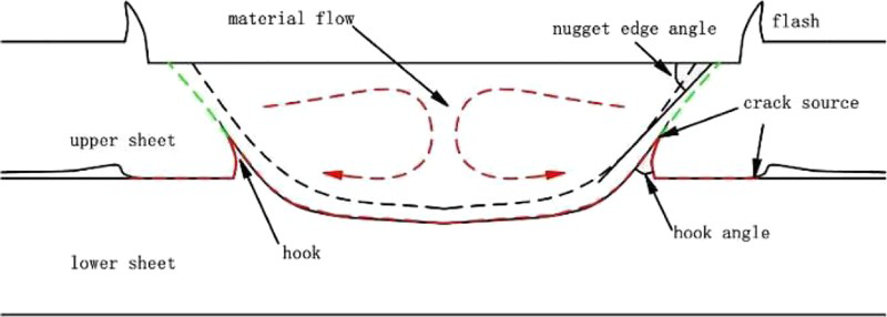
Schematic illustration of pinless FSSWed joint
Experimental
Al–Li alloy 2198-T8 of 1.8 mm thickness was lap welded by pinless FSSW as shown in Fig. 2a. The sizes of each plate were 65 mm in length by 30 mm in width. A pinless cylindrical tool with the shoulder diameter of 15 mm was used, as shown in Fig. 2b, and three involute grooves were machined on the shoulder surface. The tool was made of H13 steel.
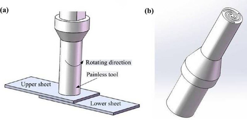
Schematic illustration of a pinless FSSW process and b pinless tool
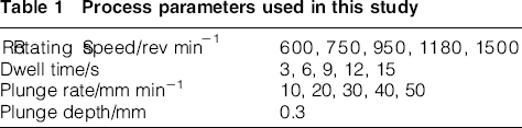
The used process parameters are listed in Table 1, according to our previous study on AA2024 alloy. 34 Three specimens were welded for each set of welding parameters. Then, the specimens were tested on a tensile testing machine to obtain the tensile shear load of joints. The cross-sectional microstructure of joints was observed by optical microscopy and scanning electron microscopy.
Process parameters used in this study
Results and discussion
Macromorphology and microstructure
Figure 3 shows the typical cross-sectional morphologies of the joints. It can be seen that when the dwell time increases from 3 to 15 s, the depth of the nugget zone (NZ) increases from 1.25 to 2.64 mm. It seems that the formability of joints is improved with increasing the dwell time. However, the HD becomes evident as marked by circles in Fig. 3. The frictional heat is mainly affected by the dwell time at the constant rotation speed. Under the shoulder, the temperature is high enough to soften the material but less than the melting temperature. 35 It could be considered that with increasing the dwell time, more heat is input to the joint and the mobility of weld material gets improved. Hence, more softened metals are generated and move downward in the upper sheet under the influence of the stirring shoulder, resulting in the increase of depth of NZ. 30 The increase of NZ sizes increases the joint strength. However, the HD is more visible because the constraint of the surrounding undeformed metals always exists and the metals in the lower sheet near the interface move upward strongly with increasing the depth of NZ.
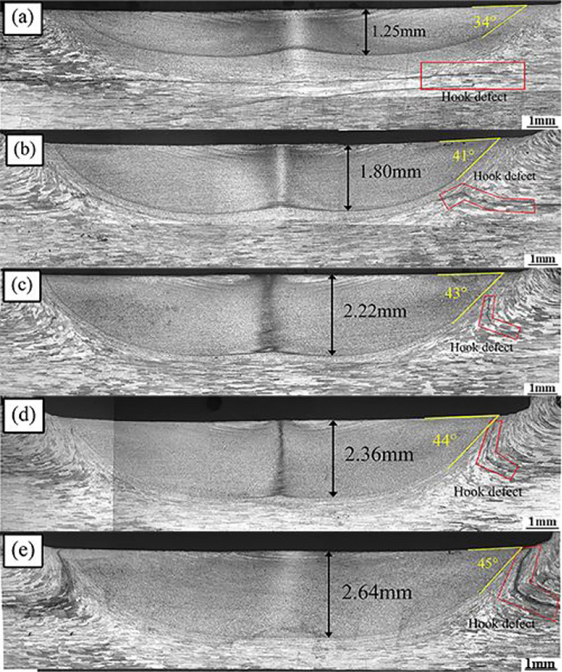
Cross-sectional morphologies of pinless FSSWed joints produced at rotational speed of 950 rev min− 1, plunge rate of 30 mm min− 1 and different dwell times: a 3 s, b 6 s, c 9 s, d 12 s and e 15 s
It is also found that the NEA changes with the dwell time, as shown in Fig. 4a. The NEA increases rapidly at the beginning and then approximates 45° with increasing the dwell time. By comparing the tensile results of different dwell times (Fig. 4b), the tensile loads reach a higher level when the NEA approximates 45°. This indicates that there exists a relationship between the joint strength and the NEA. Further analysis also shows the effect of HD on this relationship. With increasing the dwell time from 3 to 6 s, the NEA increases gradually from 34° to 41°, while the HA is obtuse. Thus, the load bearing area increases greatly and thus the tensile load increases. With increasing the dwell time, the NEA reaches ∼45°, but the tensile load decreases because of stress concentration for the acute HA. As can be seen from Fig. 4b, the optimum dwell time is 6 s at rotation speed of 950 rev min− 1 and plunge rate of 30 mm min− 1. It can be considered that the materials would deform along a favourable direction under loads. According to the maximum shear stress theory, the favourable direction is ∼45° when the materials are subjected to load in one direction.
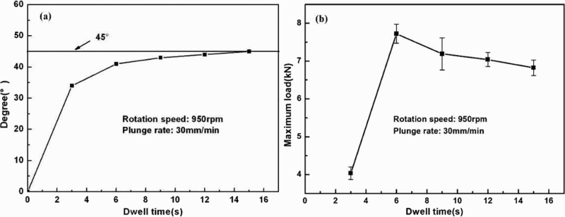
Changes of a nugget edge angle (NEA) and b tensile/shear strength
Figure 5 reveals the representative microstructure of a joint made at the rotational speed of 950 rev min− 1, plunge rate of 30 mm min− 1 and dwell time of 6 s. Similar to FSW joints, the pinless FSSWed joint has three typical zones: NZ, thermomechanically affected zone (TMAZ) and heat affected zone (HAZ). As can be seen from Fig. 5a, the joint surface is flat, the base metal exhibits elongated grains to the rolling direction, and there exists onion ring-like patterns on the top surface of the upper sheet. Close-up views of different zones as marked in Fig. 5a show that the region B indicating NZ has the microstructure consisting of refined and equiaxed grains due to recrystallisation and the stirring of shoulder (Fig. 5b). The microstructure of NZ is uniform, and there seem no defects. Region C, the TMAZ, is characterised by highly deformed grains, which are coarser than those of NZ but finer than those of BM due to the effect of stirring and friction heating (Fig. 5c and d). In case of the interface between the upper and lower sheets near the TMAZ, it becomes indistinct for being compressed under the stirring shoulder and the material flow of the upper sheet softened by friction heating. Region D is near the boundary between the upper and lower sheets and underneath the periphery of NZ. It can be seen that the boundary has an obtuse angled shape for moving upward of the extruded materials of lower sheet during stirring. Thus, it forms the HD as marked in Fig. 5d, which is the weak connection and will lower the joint mechanical properties as discussed in the previous section. Therefore, the control and elimination of HD in the pinless FSSWed joints is of significant importance. 34 Moreover, Fig. 5e shows the microstructure at the periphery of NZ, which consists of the TMAZ and the HAZ. It is also worth noting that there is a black triangular area underneath the NZ (marked as F in Fig. 5a). The high magnification observation (Fig. 5f) shows that this triangular area is not a defect but a microstructure due to etching.
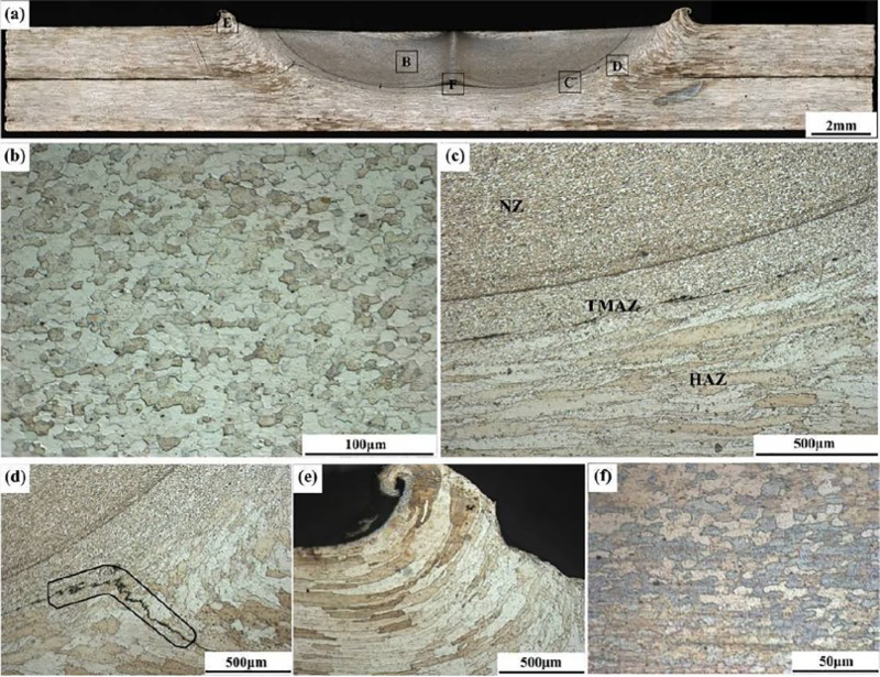
Cross-sectional micrographs of pinless FSSWed joint: a full view, b NZ, c TMAZ and HAZ, d HD, e flash zone near shoulder periphery, and f zone underneath NZ
Effect of welding parameters on mechanical properties
Tensile/shear tests
Figure 6 shows the tensile/shear results of joints made under different welding parameters. There are two types of tensile/shear results in which the loads increase with displacement initially before reaching a maximum. In addition, one type of them fractures suddenly, while another type decreases with displacement slowly until the final failure. It can be seen that the first type happens when the rotation speed is 1500 rev min− 1 (Fig. 6a) and the dwell times are 3 and 6 s (Fig. 6c). In addition, the tensile/shear strength is not significantly affected by the plunge rate (Fig. 6b), which is similar to the results of Zhang et al. 37
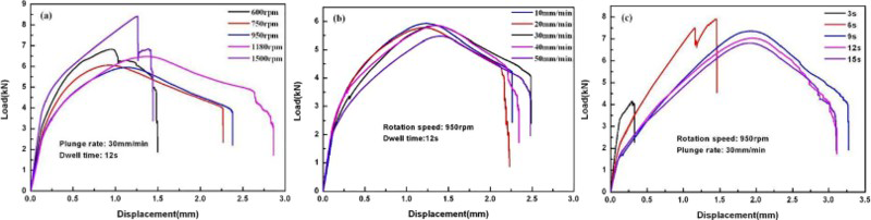
Load–displacement of pinless FSSWed joints made under different welding parameters: a rotation speed, b plunge rate and c dwell time
Figure 7 shows that the maximum loads of the pinless FSSWed joints change with rotation speed and plunge rate. The maximum loads of the joints increase generally with the increase of the rotation speed (Fig. 7a), the reason of which is that the heat production increases and the mobility of the softened materials gets improved, resulting in the more extensive material flow with increasing rotation speed. Thus, the actual depth and width of the nuggets both increase, in return improving the strength of the joints. Similar findings can also be found in the work by Tozaki et al.38, 39 Figures 4b and 7b demonstrate that the maximum loads increase initially and then decrease with the increase of plunge rate and dwell time respectively. It can be considered that when the plunge rate and dwell time are on a lower level, the friction heat generated is low and the metals are not sufficiently plasticised and have poor mobility, thus resulting in low tensile strength. When the plunge rate and dwell time are on a higher value, the frictional heat production increases and the metals are completely plasticised and have good mobility; thus, the strength of the joints gets improved. However, when the plunge rate and dwell time are overhighed, the metals are completely plasticised and the flash emerges massively during the plunge process, which results in the loss of metals. It is believed that the tensile strength is mainly affected by the HA at longer dwell time. As described previously, the HD extends obviously to the surface, resulting in the decrease of the HA. Hence, the tensile strength decreases at longer dwell time. It can be concluded from Fig. 7a that at the rotation speed of 1500 rev min− 1 corresponding to the dwell time of 12 s, plunge rate of 30 mm min− 1 and plunge depth of 0.3 mm, the tensile/shear strength reaches the maximum of 8.57 kN under the conditions used in this study.
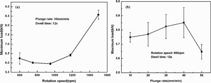
Maximum loads of pinless FSSWed joints made under different welding parameters: a rotation speed and b plunge rate
Fracture mechanism
Figure 8 shows the morphology of the tensile/shear samples and the failed joints. According to the tensile results, there are two different fracture modes (Fig. 8b and c). One is from the interface between the upper and lower sheets, which shears off completely and the nugget stays in the upper sheet (Fig. 8b). The mechanism of this fracture mode is explained by the dotted lines in Fig. 1. Owing to the expansion of the upper sheet at the periphery of shoulder and the constraint of surrounding materials, the upper sheet bends, resulting in a slight gap between two sheets, which is in agreement with Wang et al. 36 When the rotation speed or dwell time is lower, the HA is obtuse and the cracks that originated in the gap end extend along the bottom of nugget, resulting in this fracture mode. Similarly, with increasing rotation speed and dwell time, the HA changes from obtuse to acute; thus, cracks extend from the HD to the surface of upper sheet, resulting in the second fracture mode (Fig. 8c). It can be seen that the whole nugget is pulled out from the upper sheet and stays in the lower sheet finally.
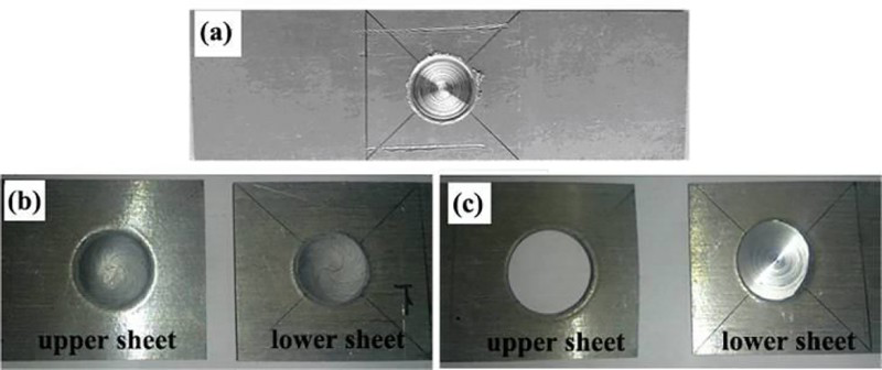
a tensile/shear sample; b first fracture mode from interface between two sheets; c second fracture mode from HD
By observing fractographs (Fig. 9), the fracture mechanism was investigated. Figure 9a is the fracture surface of a joint made under the rotation speed of 950 rev min− 1 and the dwell time of 15 s corresponding to the second fracture mode. By observing the close-up views of regions A and B, many tearing ridges and river tricks can be seen, which demonstrate the cleavage fracture for stress concentration in the HD. Figure 9b and c reveals the fracture surfaces of the joint made under the rotation speed of 950 rev min− 1 and dwell time of 6 s corresponding to the first fracture mode. Some traces in the rotation direction across the whole nugget can be seen, which suggests the material flow in horizontal section. It should be noted that by observing the close-up views of the selected regions in Fig. 9b and c (C, D, E and F), many dimples and tearing ridges can be seen, which demonstrate well bonding between the sheets. It can also be seen from Fig. 4b that the maximum load was obtained under this process condition when the effect of the parameter of dwell time was studied. In addition, the existence of dimples and tearing ridges demonstrates that the first fracture mode is the mixed fracture containing dimple fracture and quasi-cleavage fracture.
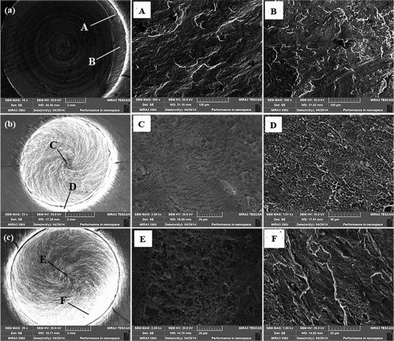
Fractographs of failure samples: a lower sheet in second fracture mode, and b lower sheet and c upper sheet in first fracture mode
Conclusions
The change of NEA and the relationship between NEA and tensile/shear strength of the pinless FSSWed AA2198 joints are investigated. The following conclusions could be drawn:
Similar to FSW, three zones with different microstructures in the cross-section of the pinless FSSWed joints, i.e. HAZ, TMAZ and NZ, are observed. As to the interface between the upper and lower sheets near the TMAZ, it becomes indistinct for being compressed under the stirring shoulder and the material flow of the upper sheet softened by friction heating. With increasing the dwell time, the NEA increases rapidly at first and then approaches 45°. It is because of the extrusion of nugget material and its flow along the surrounding ‘cold’ metal during welding. The tensile strength is determined by the changes of NEA and HA. Compared with the tensile results under different dwell times, the tensile loads reach a higher value when the NEA approaches 45° but have a slight decrease with the HA changing from obtuse to acute. The parameters of rotation speed and dwell time have great effects on the tensile/shear strength. The strength of the joints reaches the maximum of 8.57 kN corresponding to the rotation speed of 1500 rev min− 1 and the dwell time of 12 s. Furthermore, there exist two different fracture modes: the first mode fracture from the interface between the sheets and the second mode fracture from HD. In addition, under the conditions in which the second fracture mode occurs, the tensile/shear strength is reduced.
Footnotes
Acknowledgements
The authors would like to appreciate the financial support from the National Natural Science Foundation of China (grant no. 51405389), the Open Fund of Shanghai Key Laboratory of Digital Manufacture for Thin-walled Structures (grant no. 2014003) and the Research Fund of the State Key Laboratory of Solidification Processing (NPU, China) (grant no. 108-QP-2014).