
Abstract
A 780 MPa galvanised dual phase (DP) steel was two-, three- and four-layer resistance spot welded under different welding parameters and joint configurations. The splash situation, nugget sizes and tensile shear properties of the spot welds were evaluated systematically. The results showed that the splash occurring current increased in the order of two-, three- and four-layer spot welds owing to the increasing metal volume for melting. The joint configuration had a great influence on the tensile shear properties of the spot welds. The three- and four-layer spot welds with proper joint configurations had better weld quality than the two-layer spot weld. Therefore, well designed multilayer spot welds could be used to replace the commonly used two-layer spot welds in actual production.
Keywords
Introduction
For decreasing the transient lap joints in automobile design, decreasing the car body weight and solving the limitations in structural design, multilayer resistance spot welding was adopted in the process of automobile production. 1 At present, the research on multilayer resistance spot welding is mainly focused on the welding of three-layer steels. The study on the four-layer resistance spot welding has not been reported in the published papers.
Nielsen et al. 2 investigated the three-layer resistance spot weldability of thin, low carbon steel to two thicker, high strength steels of high strength low alloy steels. They illustrated that the electrode size and zinc coat had significant influences on the welding process using factorial experimentation and statistical analysis. Furthermore, they analysed the weld mechanism numerically and compared with the metallographic analyses, which showed that the bonding mechanism between the thin, low carbon steel sheet and the thicker sheet of high strength steel was solid state bonding, whereas the two high strength steels were joined by melting and forming a weld nugget at their mutual interface. Despite the absence of the typical fusion nugget through the interface between the low carbon steel and high strength steel, the weld strengths obtained were acceptable. The failure mechanism in destructive testing was the pullout failure mode. Pouranvari and Marashi 1 studied the influence of sheet thickness on weld nugget growth mechanism of the three-layer resistance spot weld. They stated that there was a critical sheet thickness at which the weld nugget size at the sheet/sheet interface was nearly equal to the fusion zone size at the geometrical centre of the weld. Above or below the critical sheet thickness, the weld nugget growth in the geometrical centre of the joint was lower or higher than that in the sheet/sheet interface respectively. Choi et al. 3 examined the fatigue behaviour of the three-layer resistance spot welds with different joint geometry and predicted the fatigue lifetime by the crack opening angle around the spot weld. They found that the joint geometry had a significant influence on the fatigue behaviour of spot welds. Harlin et al. 4 investigated the effect of electrode force on the weld growth mechanism of the three-layer resistance spot welds of both uncoated low carbon and hot dip zinc coated steels. They found that the rate of heat development was reduced in the case of the coated steel compared to the uncoated steel owing to the lower surface resistance in the presence of the zinc coating, and the electrode force had a significant effect on the location of heat development and weld nugget formation. Harlin et al. 5 compared the heat development and weld nugget growth of the two- and three-layer resistance spot welds and researched the influences of the welding conditions, sheet thickness configuration and physical material properties on the microstructure and mechanical properties of spot welds. They stated that the weld nugget formation was a balance between heat generation and heat dissipation and was dependent on sheet thickness and stack configuration. Jung et al. 6 examined the effects of welding conditions on the static strength and fatigue life of multilayer spot welds. They found that the appropriate welding procedures of multilayer spot welding could be determined by analysing the static strength and fatigue life. Coon et al. 7 investigated the effects of welding equipment, electrode shape and welding parameters on the joint strength for a three-metal thickness stack-up by a design of experiments method and developed a modified electrode stabilisation procedure. They successfully identified that the dome shaped electrode stabilised faster, produced more consistent welds and consumed less current, primarily owing to its higher current density capability. Wei et al. 8 analysed the three-layer resistance spot weldability of different advanced high strength steels. They stated that the different heat conductivities, melting points and surface electric resistances of different steels resulted in the asymmetric weld nuggets of the dissimilar spot welds
In this paper, the research was focused on the analysis and comparison of the two-, three- and four-layer resistance spot welds of the galvanised DP780 steel with different joint configurations. The effect of welding current on nugget size, tensile shear property and failure mode of the spot welds with different joint configurations was discussed. The research provides theoretical and practical guidance for the design of joint configurations of multilayer resistance spot welds.
Experimental
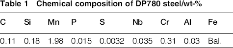
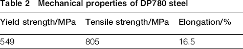
The base metal used in this study was a 1.3 mm thick cold rolled galvanised DP780 steel sheet. The chemical composition and mechanical properties of the DP780 steel are listed in Tables 1 and 2 respectively. The DP780 steel was hot dip zinc coated with an average weight of 50 g m− 2. Two-, three- and four-layer resistance spot welding with different joint configurations was conducted using a ZDT-B260-FQPLC medium frequency inverter type resistance spot welding machine and a spherical electrode with a radius of curvature for the electrode tip face of 10 mm. The electrode was made up of Cu–Cr–Zr and was water cooled during welding. 9
Chemical composition of DP780 steel/wt-%
Mechanical properties of DP780 steel
The electrode force was chosen to be 4 kN. The squeeze time, welding time and holding time were selected to be 1000, 400 and 300 ms respectively. The specific welding parameters are listed in Table 3.
Welding parameters, joint configuration, weldability and failure mode
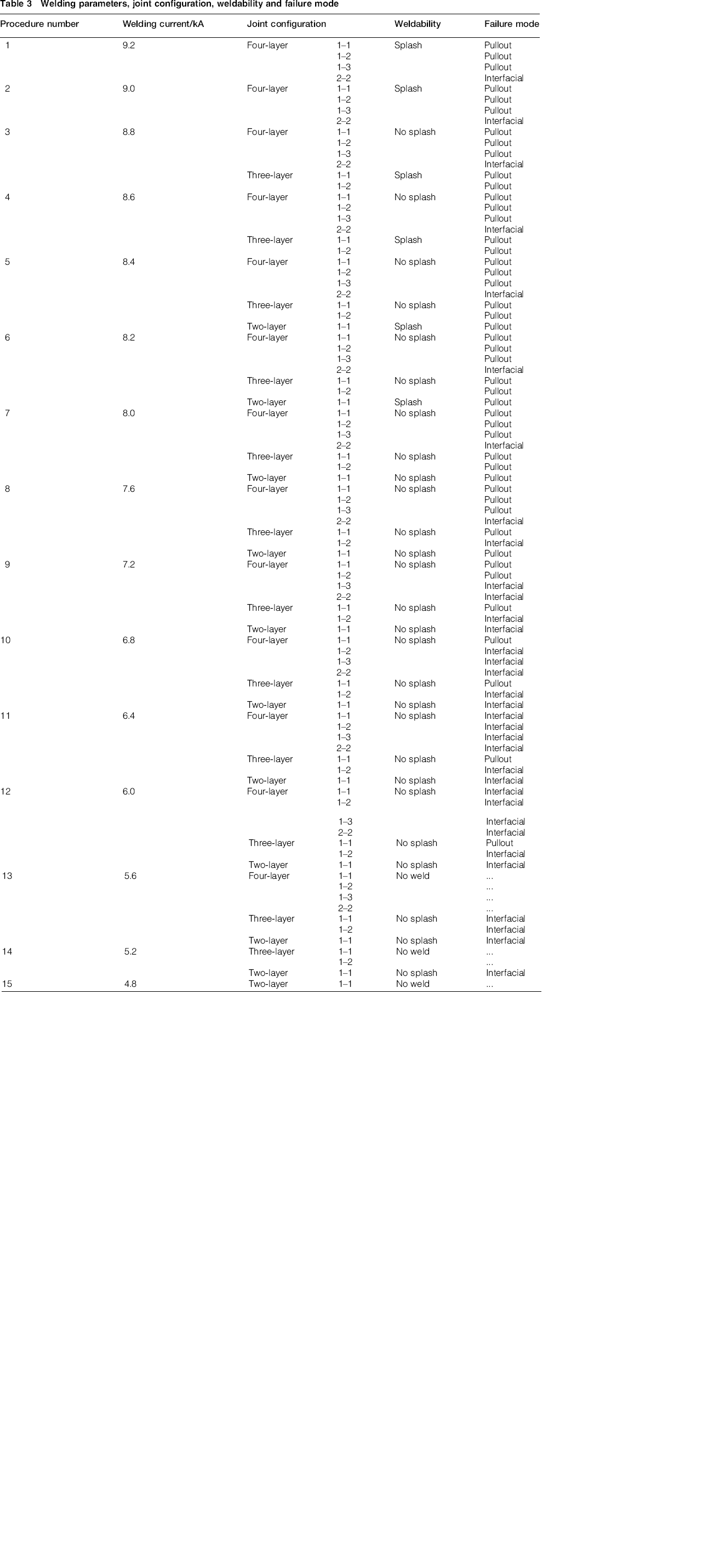
For defining the minimum splash occurring current, six spot welds for a specific parameter combination were made. Welding current increased at an interval of 0.2 kA. If splash occurred on more than two out of six welds at the same welding current, the present current could be defined as the minimum splash occurring current. 9
Tensile shear tests were used to characterise the mechanical properties of spot welds. Figure 1 shows the dimensions and joint configurations of the samples. All tests were performed at room temperature using an Instron universal testing machine with a constant crosshead velocity of 2 mm min− 1. All the load displacement curves were recorded, and failure loads and failure displacements were extracted from these curves. The failure energies were obtained by measuring the area under the load displacement curves to failure loads.9–11 Failure mode and failure location were determined from the failed samples.
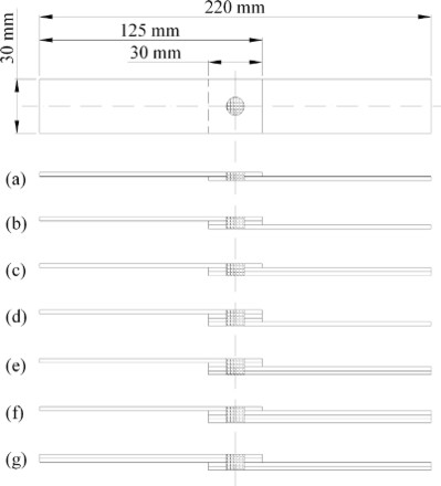
Dimensions and configurations of tensile shear test specimens of a two-layer spot weld, b three-layer spot weld with 1–1 configuration, c three-layer spot weld with 1–2 configuration, d four-layer spot weld with 1–1 configuration, e four-layer spot weld with 1–2 configuration, f four-layer spot weld with 1–3 configuration and g four-layer spot weld with 2–2 configuration
Different from the two-layer spot welds with only one sheet/sheet interface, the three- and four-layer spot welds have two and three sheet/sheet interfaces respectively.1, 2 During tensile shear tests, no matter what failure mode the welds fail in, pullout or interfacial, failure always initiates at the sheet/sheet interface. 8 Therefore, the nugget diameter along sheet/sheet interface is the most important parameter controlling the mechanical properties of resistance spot welds. 2 For macrostructure observation and nugget diameter measurement, samples were cut along the centre of spot welds. Subsequently, standard metallographic procedure was applied for macrostructural investigation. Samples were mounted using phenolic resin, ground, polished up to 0.25 μm diamond paste and then etched with 4% nital to reveal the microstructure. 9 Optical microscope was used to assess the macrostructure of different spot welds and measure physical weld attributes. The nugget diameters along sheet/sheet interfaces where failure occurred during tensile shear tests were measured using the cross-sectional macrographs of spot welds with the help of an image analyser coupled to the microscope. 9
Results and discussion
Splash
The splash occurring currents for the two-, three- and four-layer spot welding are 8.2, 8.6 and 9.0 kA respectively, as shown in Table 3. The increasing sheet layer increases the splash occurring current as a result of the increasing metal volume for melting.
Nugget diameter and tensile shear property
A series of tensile shear tests were conducted on the two-, three- and four-layer spot welds produced under different welding parameters. 9 The failure modes of spot welds are summarised in Table 3. It showed that for the two-layer spot welds, when the welding current was ≥ 7.6 kA, pullout failure mode occurred, while when the welding current was lower than 7.6 kA, interfacial failure mode occurred. For the three-layer spot welds with 1–1 and 1–2 joint configurations, the critical values for the occurrence of pullout failure mode were 6.0 and 8.0 kA respectively. When the welding current was larger than or equal to these critical values, pullout failure mode occurred; on the contrary, interfacial failure mode occurred. It was found that the three-layer spot weld with a 1–1 joint configuration had a lower critical current value for the occurrence of pullout failure mode than the spot weld with a 1–2 joint configuration. This is because the spot weld with a 1–2 joint configuration has a larger resistance for deformation than the spot weld with a 1–1 joint configuration owing to the thicker equivalent sheet thickness for the spot weld with a 1–2 joint configuration. As shown in Fig. 2, for the three-layer spot welds under the same welding current (6.4 kA), the deformation angle (α) of the weld with 1–1 joint configuration is larger than the deformation angle (β) of the weld with 1–2 joint configuration. During tensile shear tests, the stresses on spot welds include tensile stress and shear stress. Failure in tensile shear tests of spot welds is a competitive phenomenon.12, 13 The driving force for interfacial and pullout mode are shear stress (τ) and tensile stress (σ) respectively, as shown in Fig. 2. 13 When shear stress exceeds nugget shear strength, before tensile stress causes necking around the nugget, failure occurs in interfacial mode. On the contrary, when tensile stress causes necking around the nugget before shear stress exceeds the nugget shear strength, failure occurs in pullout mode. 13 Furthermore, the pullout failure always occurs in the single sheet side owing to the smaller weld nugget depth in the single sheet side compared with the double sheet side.
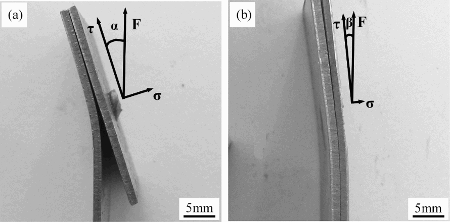
Deformation and stress distribution of three-layer spot welds with a 1–1 configuration and b 1–2 configuration
The results mentioned above indicate that weld nugget size and joint configuration are important factors governing the failure mode. For the three-layer spot welds with 1–1 and 1–2 joint configurations, during tensile shear tests, small weld nugget and 1–2 joint configuration tends to result in the interfacial failure mode, while large weld nugget and 1–1 joint configuration tends to lead to the pullout failure mode.
For the four-layer spot welds with 1–1, 1–2 and 1–3 joint configurations, the critical values for the occurrence of pullout failure mode were 6.8, 7.2 and 7.6 kA respectively, and the pullout failure always occurs in the single sheet side owing to the smaller weld nugget depth in the single sheet side compared with the triple sheets side. However, the four-layer spot welds with 2–2 joint configuration always failed in the interfacial mode during tensile shear tests. The critical current value for obtaining pullout failure mode increased in the order of 1–1, 1–2, 1–3 and 2–2 joint configurations. This is because similar to the three-layer spot welds with 1–1 and 1–2 joint configurations, for the four-layer spot welds with 1–1, 1–2 and 1–3 joint configurations, the resistance for deformation increases in order of 1–1, 1–2 and 1–3 joint configurations as a result of the same increasing order of equivalent sheet thickness. As shown in Fig. 3, for the four-layer spot welds under the same welding current (8.4 kA), the increasing orders of the deformation according to the joint configuration are 1–3, 1–2 (2–2) and 1–1. For the spot welds with 2–2 joint configuration, it is difficult to pull the weld nugget out from the double sheets owing to the larger weld nugget depth in the double sheet side compared with the single sheet side in the 1–1, 1–2 and 1–3 joint configurations. Therefore, the four-layer spot welds with 2–2 joint configuration always fail in the interfacial mode during tensile shear tests.
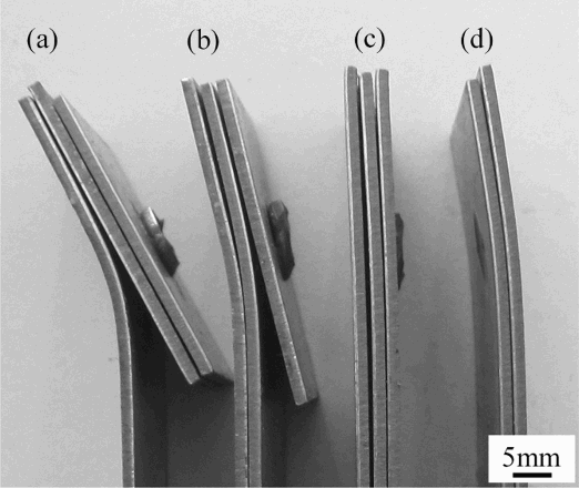
Deformation of four-layer spot welds with a 1–1 configuration, b 1–2 configuration, c 1–3 configuration and d 2–2 configuration
The cross-sections of the two-, three- and four-layer spot welds under different welding currents are shown in Fig. 4. Figure 4a–c shows the macrostructures of the two-, three- and four-layer spot welds under high welding currents; large weld nuggets were observed in these cross-sections. Figure 4d–f shows the macrostructures of the two-, three- and four-layer spot welds under low welding currents; weld nugget barely occurred under these conditions. All the cross-sections of the spot welds show the symmetric weld nuggets. For the three-layer spot welds with 1–1 and 1–2 joint configurations, the failure occurs along the same interface. As shown in Fig. 4c, for the four-layer spot welds with 1–1, 1–2 and 1–3 joint configurations, the failure occurring interfaces are the side interfaces. However, for the four-layer spot welds with 2–2 joint configuration, the failure occurring interfaces are the centre interfaces. Figure 4d indicates that for the two-layer spot weld, the nugget formation initiates at the sheet/sheet interface, and then the weld nugget grows toward the interiors of the two sheets. Figure 4e shows that for the three-layer spot weld, the nugget formation initiates at the geometric centre of the combination. This is because a considerable amount of heat occurring at the sheet/sheet interfaces is conducted to the central region of the middle sheet (geometric centre), which causes that melting would occur first in this area.1, 5 For the four-layer spot weld, as shown in Fig. 4f, the nugget formation initiates at the centre interface. This is because, on one hand, great resistive heat occurs at the centre interface itself and, on the other hand, a considerable amount of heat occurring at the side interfaces is conducted to the centre interface. The combined effects of the two factors cause that melting would occur first in the centre interface.
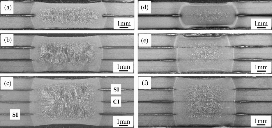
Cross-sections of spot welds of a two-layer sheets under welding current of 6.8 kA, b three-layer sheets under welding current of 6.8 kA, c four-layer sheets under welding current of 6.8 kA, d two-layer sheets under welding current of 4.8 kA, e three-layer sheets under welding current of 5.2 kA and f four-layer sheets under welding current of 5.6 kA
The effect of welding current on the nugget diameter along the failure occurring interface, failure load, failure displacement and failure energy of the spot welds with different joint configurations are shown in Fig. 5. Figure 5a shows that for all the spot welds with different joint configurations, the increasing welding current leads to the increasing nugget diameter with the exception of high welding current conditions, which can be attributed to the expulsion that limits the weld nugget growth. 14 Under the same welding condition, the nugget diameter along the failure occurring interface increased in the order of side interface of four-layer spot weld and centre interface of four-, three- and two-layer spot weld. This is because the nugget size mainly depends on the heat generation, heat dissipation and the sheet thickness of the joint.1, 5 On one hand, under the same welding condition, the increasing sheet layer number decreases the nugget diameter as a result of the increasing metal volume for melting. On the other hand, for the four-layer spot weld, the centre interface has a slower heat dissipation speed than the side interfaces, which causes that for the four-layer spot weld, the nugget diameter along the side interface is smaller than that along the centre interface.
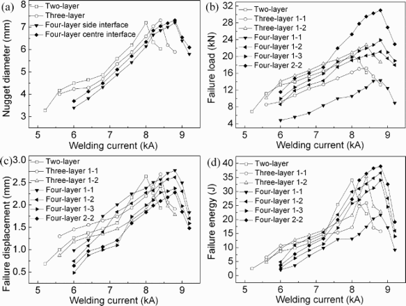
Effect of welding current on a nugget diameter along failure occurring interface, b failure load, c failure displacement and d failure energy
Figure 5b shows that with the increase of welding current, the failure load first increases and then decreases. It can be found that the change trend of nugget diameter with welding current in Fig. 5a and the change trend of failure load with welding current in Fig. 5b are similar. It can be inferred that under the same joint configurations, the change of failure load mainly depends on the change of nugget diameter caused by the changes of welding parameters.9, 15, 16 A bigger nugget diameter leads to a bigger effective area to load and higher tensile shear load bearing capacity.14, 17 As shown in Fig. 5c and d, the changes of failure displacement and failure energy with the welding current have the same trend as the change of failure load with welding current. 9
Figure 5b–d shows that the joint configuration has a great influence on the tensile shear properties of the spot welds. For the three-layer spot welds with 1–1 and 1–2 joint configurations, under the same welding condition, the spot weld with a 1–2 joint configuration has a larger failure load than the spot weld with a 1–1 joint configuration, while the spot weld with a 1–2 joint configuration has a lower failure displacement than the spot weld with a 1–1 joint configuration. This is because the three-layer spot welds with 1–2 joint configurations have larger resistances for deformation than the spot welds with 1–1 joint configurations owing to the thicker equivalent sheet thickness for the spot welds with 1–2 joint configurations. The failure energy of the spot weld depends on both the failure load and failure displacement. Under the same welding conditions, when the welding current was ≤ 6.0 kA, the three-layer spot weld with a 1–2 joint configuration has a lower failure energy than the spot weld with a 1–1 joint configuration. However, when the welding current was ≥ 6.4 kA, the three-layer spot weld with a 1–2 joint configuration has a higher failure energy than the spot weld with a 1–1 joint configuration.
For the four-layer spot welds with 1–1, 1–2, 1–3 and 2–2 joint configurations, under the same welding current, the failure load increased in the order of 1–1, 1–2, 1–3 and 2–2 joint configurations. As mentioned above, this is because on one hand for the four-layer spot welds with 1–1, 1–2 and 1–3 joint configurations, the resistance for deformation increases in order of 1–1, 1–2 and 1–3 joint configurations as a result of the same increasing order of the equivalent sheet thickness. On the other hand, the nugget diameter along the failure occurring interface of the spot weld with a 2–2 joint configuration (centre interface) is larger than the nugget diameter along the failure occurring interface of the spot welds with 1–1, 1–2 and 1–3 joint configurations (side interface), which causes the spot weld with a 2–2 joint configuration to bear a larger tensile shear load than the spot welds with 1–1, 1–2 and 1–3 joint configurations. As shown in Fig. 5c, when the welding current was < 7.6 kA, under the same welding condition, the failure displacement increased in the order of 1–3, 2–2, 1–2 and 1–1. However, when the welding current was ≥ 7.6 kA, under the same welding condition, the failure displacement increased in the order of 2–2, 1–3, 1–2 and 1–1. Compared with the low welding current conditions ( < 7.6 kA), the 1–3 and 2–2 joint configurations exchange their positions in the failure displacement increasing order in high welding current conditions ( ≥ 7.6 kA). This is because under the low welding current conditions ( < 7.6 kA), the spot welds with 1–3 and 2–2 joint configurations all failed in the interfacial mode, but the nugget diameter along the failure occurring interface of the spot weld with a 2–2 joint configuration (centre interface) is larger than the nugget diameter along the failure occurring interface of the spot weld with a 1–3 joint configuration (side interface), which caused that the spot weld with a 2–2 joint configuration to bear a larger tensile shear failure displacement than the spot weld with a 1–3 joint configuration. However, under the high welding current conditions ( ≥ 7.6 kA), the spot weld with a 2–2 joint configuration still failed in the interfacial mode, while the spot weld with a 1–3 joint configuration failed in the pullout mode. The pullout mode can experience a larger failure displacement than the interfacial mode. Therefore, under high welding current conditions, the spot weld with a 2–2 joint configuration had a smaller tensile shear failure displacement than the spot weld with a 1–3 joint configuration. The failure energy of the four-layer spot welds with 1–1, 1–2, 1–3 and 2–2 joint configurations is shown in Fig. 5d. Under the combined action of the failure load and failure displacement, when the welding current was ≤ 8.0 kA, under the same welding condition, the failure energy increased in the order of 1–1, 1–3, 2–2 and 1–2. However, when the welding current was ≥ 8.2 kA, under the same welding condition, the failure energy increased in the order of 1–1, 1–3, 1–2 and 2–2.
Comparing the nugget diameters along the failure occurring interfaces and tensile shear properties of the spot welds with different joint configurations, it can be found that the differences of the maximum nugget diameters of the spot welds with different joint configurations are negligible, while the differences of the maximum failure loads, failure displacements and failure energy of the spot welds with different joint configurations are large, which indicates that besides the nugget size, the joint configuration of the spot weld is also a main factor determining the mechanical properties of the weld. Figure 5b–d shows that for all the spot welds with different joint configurations, the maximum failure load increases in the order of four-layer weld with a 1–1 configuration, three-layer weld with a 1–1 configuration, two- and four-layer weld with a 1–2 configuration, three-layer weld with a 1–2 configuration, four-layer weld with a 1–3 configuration and four-layer weld with a 2–2 configuration. The maximum failure displacement increases in the order of four-layer weld with a 2–2 configuration, four-layer weld with a 1–3 configuration, three-layer weld with a 1–2 configuration, four-layer weld with a 1–2 configuration, two- and three-layer weld with a 1–1 configuration and four-layer weld with a 1–1 configuration. Furthermore, the maximum failure energy increases in the order of four-layer weld with a 1–1 configuration, three-layer weld with a 1–1 configuration, four-layer weld with a 1–3 configuration, two- and three-layer weld with a 1–2 configuration, four-layer weld with a 1–2 configuration and four-layer weld with a 2–2 configuration. The results mentioned above indicate that the three- or four-layer spot welds with proper joint configurations have better weld quality than the two-layer spot weld. Therefore, well designed multilayer spot welds can be used to replace the commonly used two-layer spot welds in actual production.
Conclusions
In this research, the splash situation, nugget diameter and tensile shear property of the two-, three- and four-layer spot welds with different joint configurations of the galvanised dual phase 780 steel were evaluated. From this research, the following conclusions can be drawn.
The splash occurring current increases in the order of two-, three- and four-layer spot welds as a result of the increased molten metal volume. The critical current value for the occurrence of pullout failure mode is significantly influenced by the joint configuration. The three-layer spot weld with a 1–2 joint configuration has a larger resistance for deformation than the three-layer spot weld with a 1–1 joint configuration owing to the thicker equivalent sheet thickness for the spot weld with a 1–2 joint configuration, which causes the spot weld with a 1–1 joint configuration to have a lower critical current value for the occurrence of pullout failure mode than the spot weld with a 1–2 joint configurations. For the four-layer spot welds, the resistance for deformation increases in order of 1–1, 1–2 (2–2) and 1–3 joint configurations as a result of the same increasing order of equivalent sheet thickness. Furthermore, for the spot weld with a 2–2 joint configuration, it is difficult to pull the weld nugget out from the double sheets owing to the larger weld nugget depth in the double sheet side compared with the single sheet side in the 1–1, 1–2 and 1–3 joint configurations. Therefore, the critical current value for obtaining pullout failure mode increases in the order of 1–1, 1–2, 1–3 and 2–2 joint configurations. The nugget formation of the two-layer spot weld initiates at the sheet/sheet interface. The nugget formation of the three-layer spot weld initiates at the geometric centre of the combination owing to the conduction of a considerable amount of heat occurring at the sheet/sheet interfaces to the geometric centre. The nugget formation of the four-layer spot weld initiates at the centre interface owing to the combined effects of the resistive heat occurring at the centre interface itself and the conduction of heat occurring at the side interfaces to the centre interface. The nugget size depends on the heat generation, heat dissipation and the sheet thickness of the joint. Under the same welding condition, the increasing sheet layer number decreases the nugget diameter as a result of the increasing metal volume for melting. For the four-layer spot weld, compared to the side interface, the slower heat dissipation speed of the centre interface causes the nugget diameter along the side interface to be smaller than that along the centre interface. The differences of the maximum nugget diameters of the spot welds with different joint configurations are negligible, while the differences of the maximum failure loads, failure displacements and failure energies of the spot welds with different joint configurations are large, which indicates that besides the nugget size, the joint configuration of the spot weld is also a main factor determining the mechanical properties of the weld. The three- or four-layer spot welds with proper joint configurations have better weld quality than the two-layer spot weld, which indicates that well designed multilayer spot welds can be used to replace the commonly used two-layer spot welds in actual production.