
Abstract
Underwater friction taper plug welding for X65 pipeline steel was performed using Q345 structural steel and 316L stainless steel plugs. Weld microstructures, defects formation and mechanical properties were investigated. Using Q345 plugs can produce defect free and overmatching welded joints whose impact toughness was also favourable. Lower bainite and lath martensite in the weld zone resulted in high hardness with maximum value up to 418 HV10. Using 316L plugs can significantly reduce weld zone hardness due to austenite dominated microstructure. Microcracks can easily emerge at and may propagate along γ–δ phase boundaries to form macrocracks. Intermittent cracks were found along the bonding interface of all the 316L plug welds, which should be caused by the relief of the residual stress.
Keywords
Introduction
Underwater welding technology has been playing a crucial role in the construction and repair of marine structures and subsea oil pipelines. Of all the underwater welding methods, metal arc welding dominates in the repair of underwater structures attributing to its simple equipment, versatility and low cost.1, 2 At present, problems associated with underwater metal arc welding mainly include increased diffusible hydrogen, quenched microstructures as well as the declined arc stability with the increase in water depth. 3 Although these problems can be partially improved or avoided using localised protection device or hyperbaric chamber, 4 sometimes, complex implementation and the high cost limit their application. Superior underwater welding method, therefore, is under great expectation to meet the demands of both inshore and offshore industry.
Friction taper plug welding (FTPW), also called friction hydropillar processing, was an innovative solid state joining process developed and patented by The Welding Institute during the 1990s. 5 It involves forcing a rotating tapered plug coaxially into a matching blind hole drilled at the location of a crack, thus producing a friction weld. Both frictional heat and axial force would perform during the process so that the plug material was consumed and further deposited continuously in the hole to form a sound weld. The schematic illustration of FTPW is shown in Fig. 1. Longer cracks can be repaired when a series of such welds are linked together, which is called as friction taper stitch welding. During welding process, the axial force is usually far above the outside water pressure; therefore, the weld quality is not sensitive to water depth. As a solid state joining method, FTPW enjoys the advantages of friction welding process such as low cost, high efficiency and the elimination of melting and solidification defects. 6 With the cooperation of remote operated vehicle, underwater FTPW process can be easily automated and remote controlled hence ensuring a high reliability and repeatability. All these advantages may render FTPW to become the only key technology that is eligible for the construction and remanufacturing maintenance of deep sea marine engineering structures.
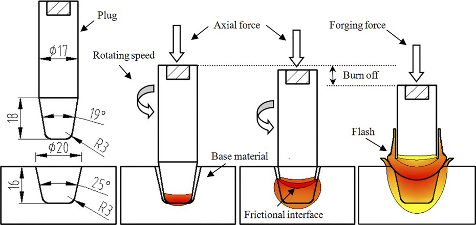
Schematic illustration of FTPW
Owing to its short history, studies about FTPW are generally rare, and most of them are concentrated on performing welding experiments in air condition.6–12 These studies have demonstrated the possibility of FTPW to be an alternative of traditional fusion welding in some circumstance. Reports about FTPW experiments conducted in underwater condition are even rarer, and these leading attempts have suggested that it is much harder to obtain defect free underwater FTP welds. Ambroziak et al. carried out friction hydropillar processing experiments on S355 low alloy construction steel and found that sufficient weld quality can be produced only for plug diameters 10 and 12 mm as a result of the constraint from welding system. 13 Cui et al. carried out FTPW experiments on the same material but using a developed high power FTPW system. Results showed that defect free welds with favourable mechanical properties could be successfully performed with 7000 rev min− 1 rotating speed and 30–50 kN axial force using the identical material to machine the tapered plugs. However, hardness of weld zone (WZ) is significantly increased as a result of both microstructural evolution and strain hardening (maximum value higher than 500 HV10). 14
In our previous work, we have conducted initial trial for pipeline steel in underwater condition using Q235 and X65 steel as the tapered plugs. 15 We concluded that plug materials can lead to significant influence on defects formation, microstructural evolution and mechanical properties. However, the results are still scarce. In order to improve the property of FTP weld in underwater, we explore the weldability and quality for X65 pipeline steel with Q345 and 316L steel plugs and further explain the main reasons and their inherent relationships. Q345 is a widely used high strength low alloy steel in engineering field, while 316L stainless steel was selected with the prospect of improving mechanical properties. Both plug materials have the basic corrosion resistance, which can meet the offshore engineering applications: 316L stainless steel has excellent corrosion resistance in sea water condition, and Q345 was also used widely after proper surface anticorrosion treatment.
Experimental
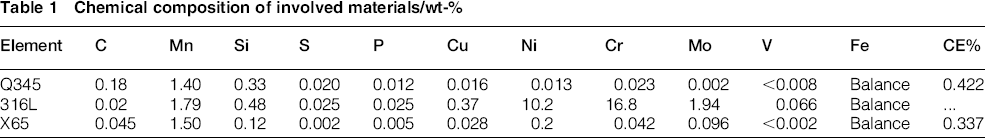
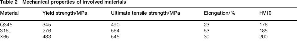
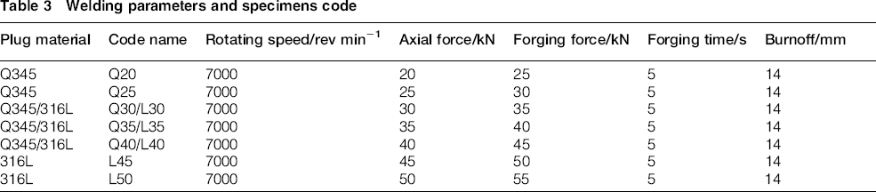
In this study, X65 pipeline was used to machine dimensions of 200mm L × 50 mm W × 30 mm H base material. Several Q345 steel bars and AISI 316L stainless steel bars were used to prepare Q345 plugs and 316L plugs respectively. Tables 1 (CE% = percentage of carbon equivalent AWS) 16 and 2 present tested chemical composition and nominal mechanical properties of the involved materials. The blind hole to be repaired and the tapered plugs were machined in advance according to the geometrical sizes shown in Fig. 1. All the welding experiments were conducted in FTPW system designed by Tianjin University in 2012 according to the process parameters as listed in Table 3, which were set based on the capacity of the equipment and our previous work. Before welding, the plugs were fixed in the welding head, and the base materials were fixed in a tank containing enough water that can submerge the base material totally so as to simulate underwater condition as shown in Fig. 2. In order to obtain high quality welds, the base material was fixed elaborately to ensure that the hole is coaxial with the plug.
Chemical composition of involved materials/wt-%
Mechanical properties of involved materials
Welding parameters and specimens code
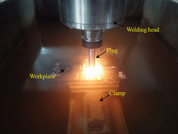
Underwater wet FTPW process
After welding, welds were first cross-sectioned and then subjected to metallographic preparation. The etch solution for carbon steel was 4% nital, while nitric–glacial acetic–hydrochloric acid reagent (10 mL+10 mL+10 mL) was prepared for 316L stainless steel. Defects analysis and microstructural observation were conducted by optical microscope, X-ray diffraction and scanning electron microscope (SEM). 432SVD Vickers hardness tester was used with a 10 kgf load and 15 s holding time to conduct hardness survey. Tensile tests were performed using CSS-44100 universal testing machine with load rate of 5 mm min− 1 at room temperature to evaluate bonding quality. Standard Charpy V notch specimens were machined to evaluate the impact toughness of WZ at 0°C. The extracted position and dimensions of tensile and impact specimens are shown in Fig. 3.
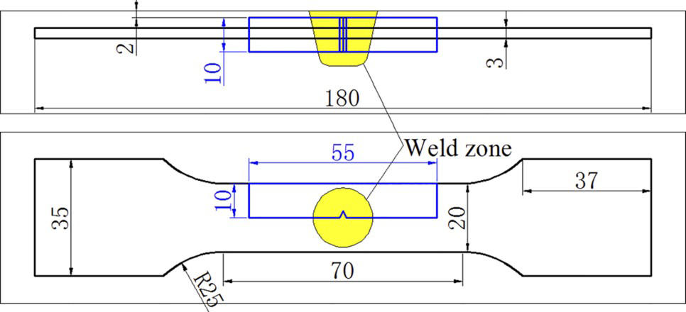
Extracted position and dimensions of tensile and Charpy impact specimen
Results and discussion
Cross-section morphology
Figure 4 gives cross-section morphologies of the obtained joints. For all the welds, there is a distinct boundary between the plug and hole. In this paper, it is defined as bonding line (BL) for convenience of later discussion. Besides, three typical zones including base material, heat affected zone (HAZ) and WZ can be identified. The HAZ size of 316L plug welds is significantly larger than that of the Q345 plug welds. Besides, the HAZ size for both plug welds tends to decrease with increasing axial force. Intermittent cracks were found in all the 316L plug welds along the bonding interface. An obvious crack appeared in the WZ of L35 specimen. The defects associated with 316L plug welds could be visually inspected.
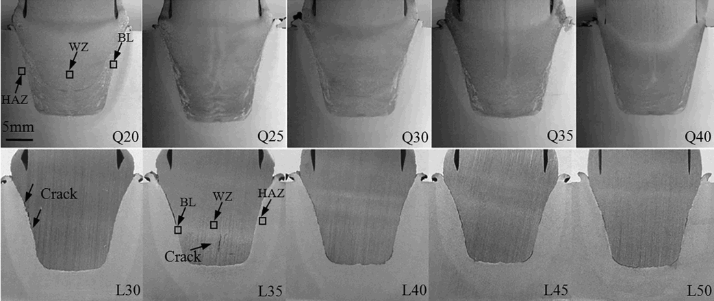
Cross-section morphologies of obtained joints
Optical microscope observation shows that all the Q345 plug welds are defect free even in the rounded corner where defect is apt to occur.10, 11, 14 Figure 5 presents the bonding feature of Q30 rounded corner. The bonding interface is clearly identified due to the distinct microstructural evolution on both sides. A decarburised layer was found at plug area near the bonding interface and a carburised layer in X65 base material. This is due to the carbon diffusion from high carbon content Q345 to low carbon content X65 steel. The emergence of diffusion layer indicates that metallurgical bonding is achieved between the plug and base material.
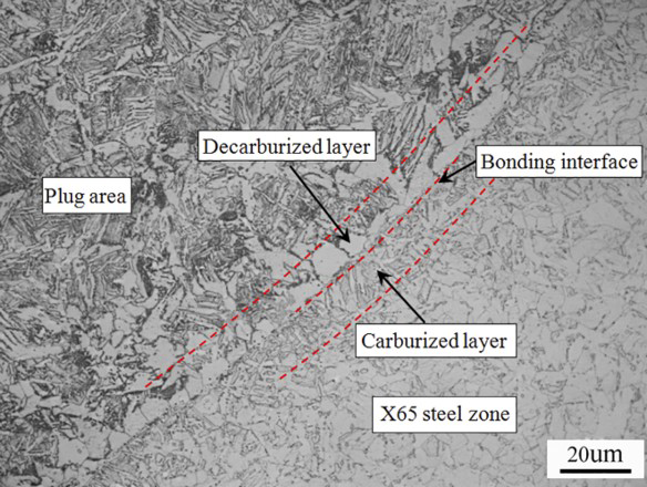
Bonding feature of Q30 rounded corner
Figure 6 gives the HAZ width (tested at 8 mm below the top surface) and welding time as a function of axial force. With the increase in axial force, welding time gradually decreased for both plug welds, which also led to the decrease in HAZ size. The 316L stainless steel is very viscous during welding process, and the poor flowability caused it took more time to finish the set burnoff value. The extremely long thermal–mechanical process caused the HAZ size of 316L plug welds to be significantly larger than that of Q345 plug welds.
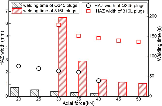
Heat affected zone width and welding time under different processing conditions.
Defects formation of 316L plug welds
L35 specimen was selected to perform crack analysis in BL and WZ. Figure 7a and b shows SEM images of the rounded corner and side wall respectively. Bonding has been achieved in local interface both in the rounded corner and side wall.
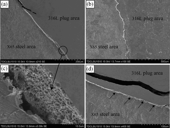
Figure 7c is a magnified image of the region marked by a circle in Fig. 7a. The bare fracture surface is clean without any oxidation or exotic particles. Large amounts of dimples were bestrewed with the bare fracture surface. It is believed that the formation of this crack is probably a stress relief process since large residual stress is believed to be generated around the bonding interface as a result of the huge difference of the two materials in composition, grain structure and thermal expansion coefficient. 17 It is well known that even in air condition, without careful control of welding process, crack is easy to occur with dissimilar weld joints between carbon steel and stainless steel as a result of the residual stress in the bonding interface. 18 In this experiment, severe cooling condition inflicted by the water obviously aggravated the residual stress of the welded joints. In Fig. 7d, the bonding interface is not fully split due to the stress that has been released by crack propagation around this region. To sum up, an interface crack is believed to emerge under the circumstance when the ductility of the bonding interface is insufficient to offset strain caused by residual stress relief.
In order to analyse the formation mechanism of WZ crack, a cube that fully contains the crack region was elaborately extracted by wire cut and separated along the crack with crack surface unaffected as much as possible. Fracture surface of the two segments as shown in Fig. 8a presents typical intergranular brittle fracture morphology. The desquamate grain sizes are in the vicinity of 100 μm. Figure 8b is microstructure of the region near the crack. X-ray diffraction results as shown in Fig. 8c demonstrated that plug area still maintains γ phase (face centred cubic crystal structure), but δ ferrite (body centred cubic crystal structure) was produced along the coarse austenite boundaries after FTPW. Observation by SEM revealed that microcrack easily occurs in the phase boundary of γ and δ phase as shown in Fig. 8d.
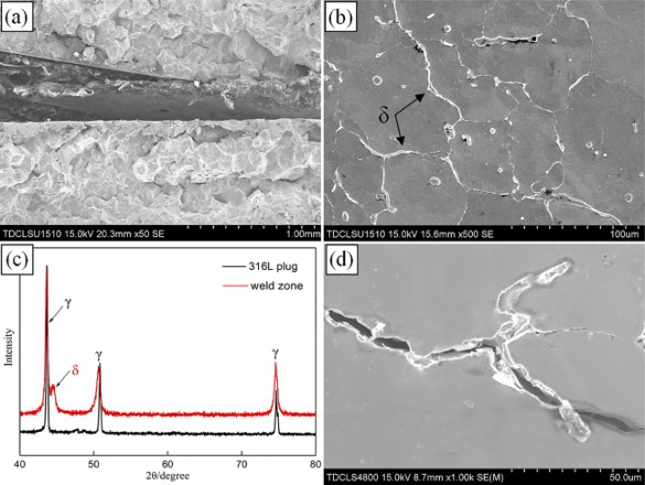
δ ferrite is a high temperature phase usually formed in regions that are heated above 1150°C with some of them being retained on cooling. 19 Thermal cycles of FTPW conducted in air have indicated that temperature of HAZ could reach 1160°C, and obviously, the WZ is surely higher.6, 9 Under the severe friction heating and cooling condition caused by water, δ ferrite was produced and retained in the WZ. In fusion welded joints, a small amount of fine δ ferrite is usually desired so as to prevent formation of hot crack.20, 21 However, the δ ferrite in FTP WZ is slender and distributes continuously along the coarse austenite boundaries. This kind of distribution characteristic causes microcracks to easily emerge at and may propagate along the γ–δ phase boundaries to form macrocracks when the WZ is subjected to severe plastic deformation during welding process.
Hardness and microstructure
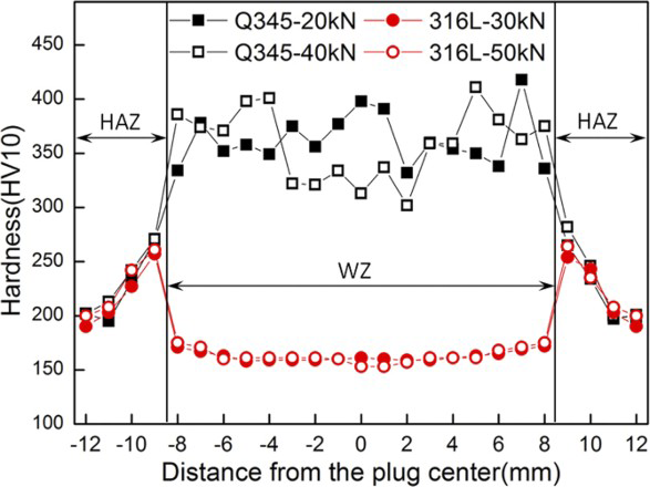
Hardness has always been a major concern to evaluate the performance of underwater weld joint. Figure 9 gives the hardness distribution of both plug welds tested at 7 mm below the top surface. The influence of plug materials and axial forces on the HAZ hardness is small. With the decrease in distance from BL, the hardness tends to increase for both plug welds. The maximum hardness is 282 HV10 for Q345 plug welds in 40 kN axial force, while it is 264 HV10 for 316L plug welds in 50 kN axial force both at a distance of 0.5 mm from the BL. However, hardness profile in the WZ is significantly different. For Q345 plug welds, the hardness mainly ranges from 300–400 HV10 with the maximum value up to 418 HV10 at a distance of 1.5 mm from the BL at 20 kN axial force. But for 316L plug welds, the hardness maintains in the vicinity of 160 HV10 almost without deviation.
Comparison in hardness levels between Q345 and 316L plug welds
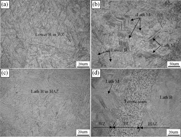
Considering the huge difference in hardness distribution in WZ and HAZ, microstructures in three typical regions, namely, WZ, BL and HAZ as shown in Fig. 4, were observed. Optical microscope observation shows that microstructures in the WZ of Q345 plug weld mainly consist of lower bainite and lath martensite as shown in Fig. 10a and 10b respectively, while microstructure in the HAZ near the BL is majorly lath bainite as shown in Fig. 10c.22, 23 Figure 10d gives the morphology of BL. The BL is a fine ferrite seam with a width of ∼50 μm. This fine ferrite seam is believed to be caused by carbon loss at elevated temperature and the frictional shear process of the FTPW process. The same phenomenon has been detected when using Q235 and X65 steel as the tapered plugs, which seems to be a common rule during FTPW process when carbon steels are welded. 15 The microstructure in the left of BL is mainly lath martensite, while that in the right of BL is lath bainite and some granular bainite, which is similar to the microstructures in WZ and HAZ respectively.
Microstructure of Q345 structural steel is composed of ferrite and pearlite, while X65 steel consists of fine ferrite and pearlite. During FTPW process, the frictional heat causes the plug material and base material to proceed austenising first and then transform to quenched structures under severe cooling phase. The carbon equivalent (CE) method is the most common and easiest way to research steel weldabilities and evaluate the hardening tendency of welded joint. Quenched microstructures such as lower bainite and martensite tend to increase as the CE or cooling rate increased. 24 It is well known that when CE is higher than 0.4–0.6, the weldability of welded joint tends to become worse, and quenched microstructure may emerge. The CE is 0.422 for Q345, while it is 0.337 for X65 steel. The difference in CE should be responsible for the different microstructural transformation in WZ and HAZ, which also explains the hardness distribution of Q345 plug welds.
316L is austenite stainless steel, and its microstructure is mainly single phase austenite due to its high nickel content. For 316L plug welds, microstructure in the HAZ is also majorly composed of lath bainite similar to Fig. 10b; however, in the WZ, due to the plug's high nickel content, the microstructure is still dominated by austenite and some δ ferrite produced at the austenite grain boundary after welding thermal cycle just like microstructures presented in Fig. 8b. This kind of microstructure distribution characteristic results in a low hardness profile.
Tensile properties and Charpy impact toughness
For defect free Q345 plug welds, tensile test and Charpy impact test were performed to evaluate the bonding quality and toughness of the welded joints.
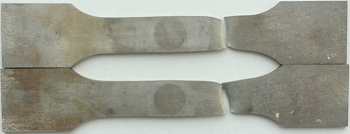
Tensile tests showed almost all specimens (one Q20 specimen fractured at the bonding interface with ultimate tensile strength of 330 MPa) broke in the base material far away from the plug area and HAZ. This means that selecting Q345 steel to machine the plug can realise overmatching condition of the welded joints. The elongation is reduced when compared with the X65 base material. Figure 11 gives the tensile specimens after testing. Deformation majorly concentrates on the soft regions of base material area as a result of the overmatching welded joints.
Tensile test specimen with failure occurs in base material
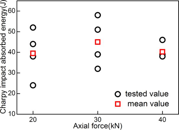
The results of the Charpy impact tests can be seen in Fig. 12. The deviation of the measured absorbed energy is relatively high at 20 and 30 kN axial force, but the mean value of four specimens is very close, all in the vicinity of 41 J. The lowest measured value is 24 J at 20 kN, and the maximum is 58 J at 30 kN axial force. All of the impact energy could match the requirement for class B welds in AWS D3.6 Underwater Welding Code, where 19 J is the lowest and 27 J is the average are needed. 25
Charpy impact absorbed energy of Q345 plug welds
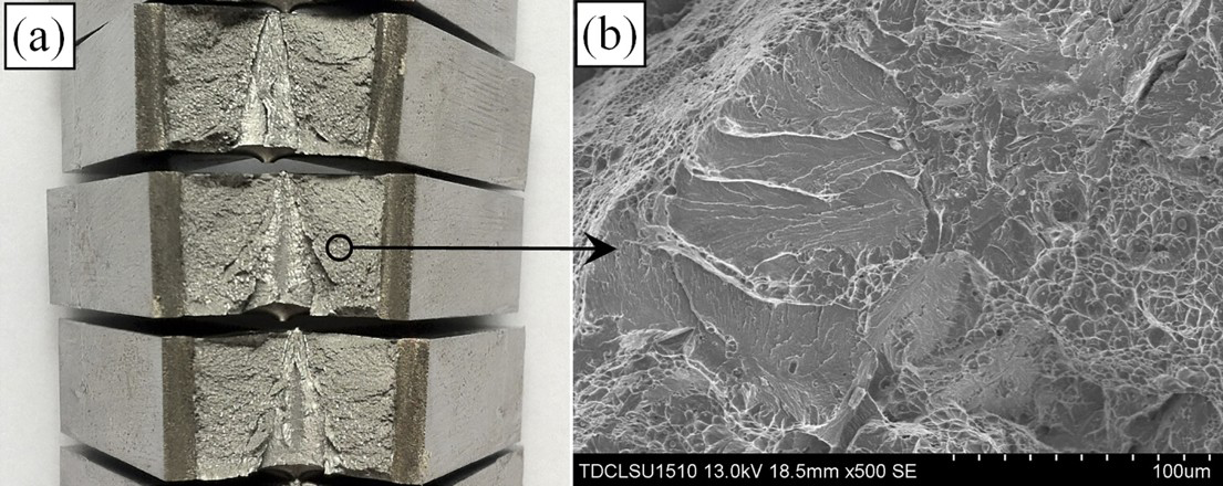
Figure 13a shows the fracture surface macrographs of the impact specimens. The fracture surface is grey and flat in general with few reflection plains for all the specimens. Figure 13b is a typical SEM morphology of the fracture surface. The overall observation of the fracture surface includes both ductile and brittle features since a lot of dimples and large cleavage plains could be found. The large cleavage plains should be the reflection plains in macrographs. Microstructure observation has demonstrated that the WZ of Q345 plug welds majorly consists of lower bainite and lath martensite. The acicular ferrite in lower bainite is fine and homogeneous with high dislocation density. Besides, a large amount of fine and dispersive carbides were precipitated inside the fine acicular ferrite. 23 Therefore, lower bainite is believed to have both high strength and high toughness. However, the lath martensite in the WZ is generally thought to be unfavourable to the toughness due to its poor plastic deformation capacity. Microstructure distribution characteristic in the WZ should be responsible for the quasi-cleavage characteristic of the impact fracture morphology.
Conclusions
In this study, underwater FTPW for X65 pipeline steel was performed using Q345 structural steel and 316L stainless steel plugs. Weld microstructures, defects formation and mechanical properties of the repaired welds were investigated and compared. The main conclusions are summarised as follows.
Using Q345 plugs can produce defect free underwater FTP welds. However, when 316L plugs were used, intermittent cracks were found along the bonding interface for all the welds, which should be caused by the relief of the residual stress. δ ferrite was produced in the WZ after FTPW, and microcracks can easily emerge at and may propagate along γ–δ phase boundaries to form macrocracks. Martensite and lower bainite were produced in the WZ of Q345 plug welds with maximum hardness up to 418 HV10 due to the harsh cooling condition caused by water. Using 316L plugs can significantly constrain hardness increase in the WZ where microstructure is dominated by austenite due to the high nickel element content of the plug. Using Q345 plug can realise overmatching condition with failure occurring in the base material far away from the plug area. The mean value of Charpy impact absorbed energy in the WZ can reach 41 J at 0°C owing to the high toughness lower bainite microstructure.
Footnotes
Acknowledgements
The authors acknowledge the financial support of Tianjin applied basic and frontier technology research key project (grant no. 14JCZDJC38800). Great thanks are given to J. Cao and W. Xu from Offshore Oil Engineering Co., Ltd of China for supporting the experiment and positive suggestions.