
Abstract
The presence of organic acid species in formation water of oil and gas reservoirs has long been suspected to contribute to the corrosivity of CO2 corrosion. The effect had been regarded as secondary until new findings in the 1980s and 1990s revealed the increase in corrosion rate in CO2 environment with the presence of acetic acid species. This is potentially detrimental as most of the predictive models used in corrosivity assessment of the field do not incorporate considerations of the effects of acetic acid species. This paper presents experimental corrosion rates of carbon steel in CO2 environments with the presence of low concentrations of acetic acid species under the turbulent flow conditions, based on linear polarisation resistance analysis. The experimental corrosion rates are compared with the corrosion rates predicted by industrial predictive models such as Norsok and Cassandra. Based on the findings, the authors can conclude that acetic acid species increase the corrosion rate of carbon steel in CO2 corrosion and standard predictive models do not capture this effect. An empirical equation is proposed to cater for the presence of low concentrations of acetic acid in CO2 corrosion under turbulent conditions.
Introduction
The main objective in the corrosion design based on an oil and gas exploration and production project is to ensure cost optimisation and structural integrity of installation. This entails detailed evaluation of all possible corrosion risks that govern the basis of material selection in the design stage. The correct selection of materials and corrosion mitigation methods is critical in order to withstand the potential corrosivity of the hydrocarbon sources throughout the design life.
Corrosivity in oil and gas pipelines and associated equipment originates from the composition of the oil and gas sources. Primary constituents of the sources are carbon dioxide (CO2), hydrogen sulphide (H2S), dissolved oxygen and organic acids. The most frequent organic acid is acetic acid. CO2 corrosion is a complex process as it is not only affected by the presence of multicorrosive species but also by other operational parameters such as flow, pH and material characteristic. The combined effects of these environmental and operational factors produce more aggressive environment which could result in increasing corrosion rate.
Some experiments had been conducted to study the effect of the presence of HAc in CO2 corrosion under static and dynamic conditions.1–3,6–11 Mixed findings were obtained with regard to the effect of range of HAc concentrations on the CO2 corrosion rate. Ismail10 has found that at a higher HAc concentration more than 400 ppm, HAc shows an inhibitive property. On the contrary, low HAc poses great concern as it increases corrosion rate2 and causes failure in the field.4 However, the works reported on the experiments were conducted in a large interval of HAc concentration. Most of the input start at 10 ppm and then jump to 100 ppm. Not much work conducted below 100 ppm with tight interval of HAc concentrations. This is important since most of study assumes linear correlation between HAc concentration and corrosion rate in the lower concentration.
Various CO2 corrosion predictive models were then developed based on studies in the laboratory. These predictive models are used as a tool in corrosion design basis to predict the possible corrosion rate that will occur in the system. The predicted data are used as the basis of material selection in the design stage and then provide inputs for maintenance and inspection strategies in the operation stage. On the other hand, most of CO2 corrosion predictive models cost are quite expensive and several publicly available CO2 corrosion prediction models such as Norsok,12 Cassandra13 and de Waard et al.14–17 do not deliberate on HAc effect in the corrosivity analysis although HAc is known as a hazardous species that gives unreliable corrosion as highlighted by Fatah et al.18 and Woollam et al.19 Hence, accurate prediction data are important in the sense that the correct material selection and corrosion mitigation method which is crucial to withstand the design live can be implemented. This is not only relevant to safety issues but also to cost, by avoiding both under and over designs.
Thus, the objective of the study is to establish the effects of low concentration of HAc on the CO2 corrosion under turbulent flow conditions. The effects are to be incorporated in a predictive model so that reliable prediction of CO2 corrosion of the carbon steel pipeline with the presence of HAc, especially at low concentrations, can be achieved.
Experimental
Electrochemical studies were performed under turbulent conditions with the use of rotating cylinder electrode (RCE) apparatus. The test assembly consists of a standard one‐litre glass cell with 3% NaCl solution saturated with CO2 for at least one hour before the exposure of electrode. The pH of the solution could be adjusted by adding an amount of 1M NaHCO3. The pH value was checked by microcomputer pH metre Mettler‐Toledo Model 320, which had been calibrated using standard buffer solutions. The required test temperature is set through a hot plate. The electrochemical measurements are based on a three‐electrode system, using a commercially available potentiostat with a computer control system. The reference electrode used is an Ag/AgCl and the auxiliary electrode is a platinum electrode. Corrosion rates were calculated based on the linear polarisation resistance method.
The RCE apparatus used in this research was made by PINE Research Instruments (Model AFMSRCE) with rotation speeds from 50 to 10·000 rev min−1. This equipment has an accuracy within 1% of reading. The shaft and the specimen holder of the RCE were made of stainless steel. The cylindrical sample was held in position with the use of polytetrafluoroethylene washers and an end cap screwed into the end of the specimen holder. The cylindrical samples used in the RCE apparatus were machined from commercial mild steel grade with diameter 12 mm and length 8 mm. The sample surface was then polished to 600 grade finish using silicon carbide papers. The specimen was degreased and rinsed with ethanol and deionised water before immersion.
The corresponding calculated wall shear stress for the dynamic experiment is presented in Table 1.
Wall shear stress at different rotational speeds for turbulent conditions
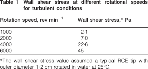
*The wall shear stress value assumed a typical RCE tip with outer diameter 1·2 cm rotated in water at 25°C.
Linear polarisation resistance
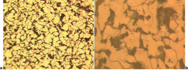
This method is based on the linear approximation of the polarisation behaviour at potentials near the corrosion potential. Polarisation resistance R p is given by Stern and Geary20 equation

The Stern–Geary constant B is estimated using a cathodic Tafel slope of 120 mV dec−1 and an anodic Tafel slope of 80 mV dec−1. This is in agreement with the available data, such as Sun et al.5 and Ismail.10
The corrosion current can be related directly to the corrosion rate from Faraday's law

Linear polarisation resistance measurements were performed by firstly measuring the corrosion potential of the exposed sample and subsequently sweeping from −10 to +10 mV with the sweep rate 10 mV min−1.
Materials
Experiments under dynamic conditions were conducted with mild steel (BS 970: 080A15) with the composition of Fe–0·148C–0·175Si–0·799Mn–0·01P–0·032S–0·069Cr–0·014Mo–0·065Ni (wt‐%).
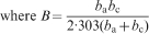
The microstructure of used material is shown in Fig. 1. It reveals that this material is low carbon steel which consists of ferrite and pearlite structure. The ferrite structure is shown by empty face, while pearlite is shown by dark face. However, since the pearlite structure is too fine the laminar structure can not be seen clearly.
Microstructure of mild steel BS970: 080A15
Results and discussion
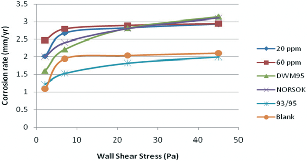
The results from the RCE experiment are compared to the DWM 95, Cassandra 93/95 and Norsok models. DWM 95 and Cassandra 93/95 take velocity as input whereas Norsok takes wall shear stress as input. The results from blank, 20 ppm HAc/Ac and 60 ppm HAc/Ac cases were compared with those models.
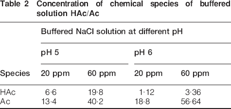
The 20 and 60 ppm acetic species here represent the mixture of free acetic acid (HAc) and acetate ions (Ac). The concentration of each species varies with the pH of the solution. This concentration of HAc and Ac at the buffered pH is shown in Table 2. It is assumed that the concentration of the acetic species remain the same at different temperatures since the equilibrium constant for acetic acid KHAc varies a little with temperature.
Concentration of chemical species of buffered solution HAc/Ac
Figures 2–7 show comparison between the experimental results and prediction models.
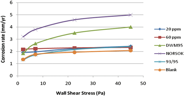
Comparison between experimental corrosion rates and predictive models at 25°C, pH 5
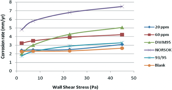
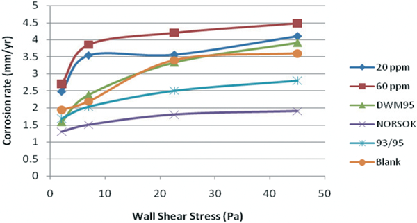
Comparison between experimental corrosion rates and predictive models at 40°C, pH 5
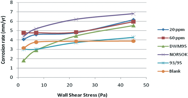
Comparison between experimental corrosion rates and predictive models at 60°C, pH 5
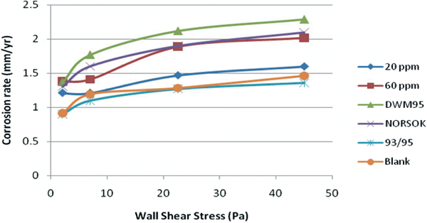
Comparison between experimental corrosion rates and predictive models at 25°C, pH 6
Comparison between experimental corrosion rates and predictive models at 40°C, pH 6
Comparison between experimental corrosion rates and predictive models at 60°C, pH 6
In general, the results show that for both pH 5 and 6, with various temperatures of 25, 40 and 60°C under turbulent conditions, Cassandra 93/95 has a good agreement with blank experimental result. While Norsok and DWM 95 model, predict higher corrosion rate than experimental results.
Co2 prediction with presence of HAc under turbulent flow conditions
A corrosion prediction equation is developed based on the experimental results of the RCE flow simulated tests conducted at pH 5. The RCE tests represent the turbulent flow conditions. The prediction equation then validated against the experimental data from the tests conducted under other test conditions.
Rotating cylinder electrode tests at 25°C
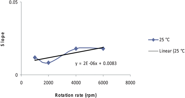
The relationship between corrosion rate and HAc concentration is plotted at different rotation rates as shown in Fig. 8 below. This relationship is plotted in Fig. 9.
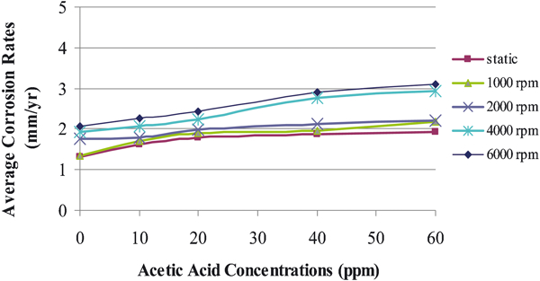
Rotating cylinder electrode tests at 25°C
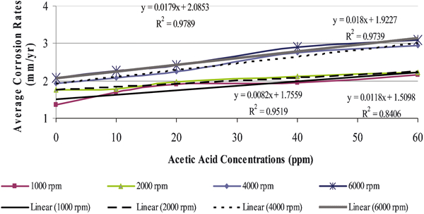
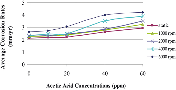
Prediction based on RCE tests at 25°C
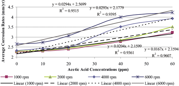
Corrosion rates vary linearly with the concentration of the added HAc. In general, this linear relationship can be represented by best fit equations. The best fit equations, as shown in Fig. 9, reveal a good correlation and suggest a good linear relationship between corrosion rate and the HAc. This relationship can be expressed as
Thus, the corrosion rate of mild steel in CO2 containing solution with the presence of HAc can be predicted by adding the contribution of the HAc to the blank corrosion rate.
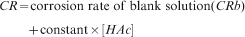
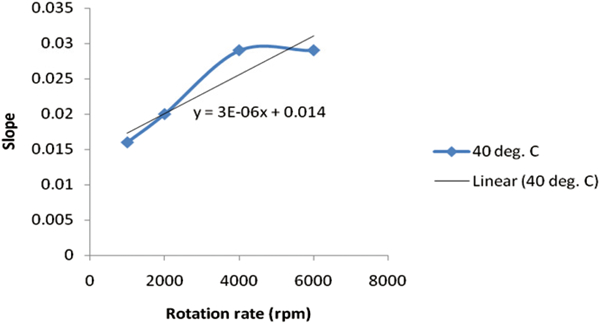
The constant in the equation, which is the slope of the curve, varies with rotation rate and could be approximated by plotting the slopes against rotation rate as shown in Fig. 10.
Variation of slopes with rotation rate
Thus, the corrosion rate prediction at 25°C can be expressed as

Rotating cylinder electrode tests at 40°C
Similarly at 25°C, the relationship between corrosion rate and HAc concentration is plotted at different rotation rates as shown in Fig. 11. The linear relationship is plotted in Fig. 12.
Relationship between corrosion rate and HAc concentration as plotted at different rotation rates at 40°C
Best fit equations for relationship between corrosion rate and HAc concentration as plotted at different rotation rates at 40°C
The change of the slope with the rotation rate is plotted below, as shown in Fig. 13.
Variation of slopes with rotation rate
Thus, the corrosion rate prediction at 40°C can be expressed as

Rotating cylinder electrode tests at 60°C
Similarly at 25 and 40°C, the relationship between corrosion rate and HAc concentration is plotted at different rotation rates as shown in Fig. 14. The linear relationship is observed below 40 ppm, which is the inhibitive threshold of HAc concentration. This relationship is plotted in Fig. 15. The variation of the slopes with rotation rate is shown in Fig. 16.
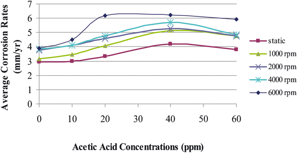
Relationship between corrosion rate and HAc concentration as plotted at different rotation rates at 60°C
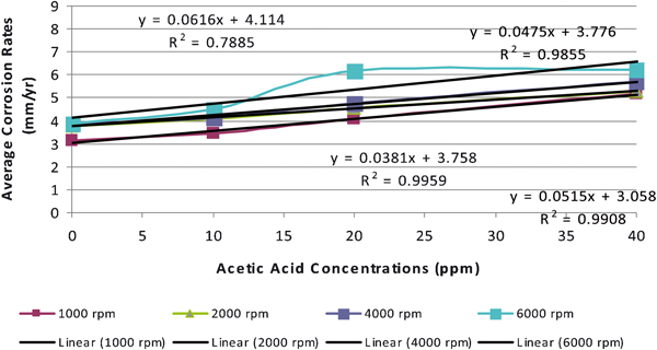
Best fit equations for relationship between corrosion rate and HAc concentration as plotted at different rotation rates at 60°C
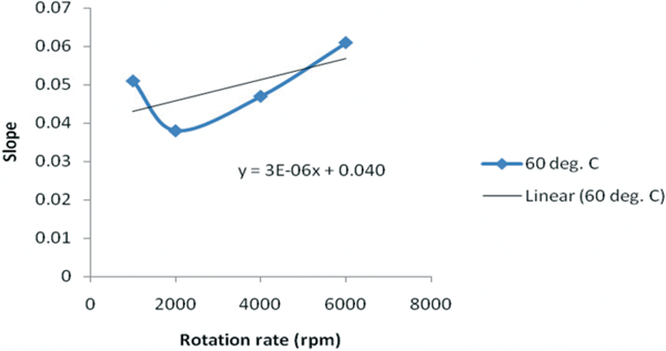
Variation of slopes with rotation rate
Thus, the corrosion rate prediction at 60°C can be expressed as

In order to include the effect of temperature in the prediction equation, the variation of the constants with the temperatures at 25, 40 and 60°C is plotted for each rotation rate and this is presented in Fig. 17.
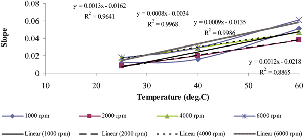
Variation of constant with temperature
The authors observe that the corrosion rates are affected by the increase in rotation rate at 25, 40 and 60°C. The prediction equation can be expressed as

Comparison of prediction equation and commercial prediction model
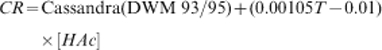
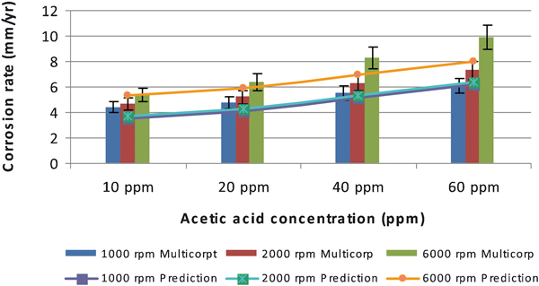
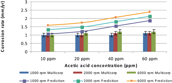
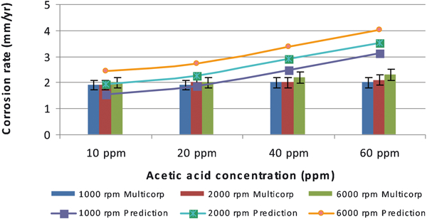
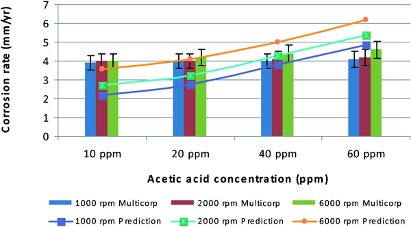
The comparison of the predicted corrosion rates based on the above prediction equation [using Cassandra (DWM 93/95) as the CRb] and commercial model are shown in Figs. 18–23. The comparisons are conducted under different conditions of pH 5 and 6 at 25, 40 and 60°C with various HAc concentrations and rotational rates. The prediction equation, derived from the RCE tests at pH 5 is taken as below
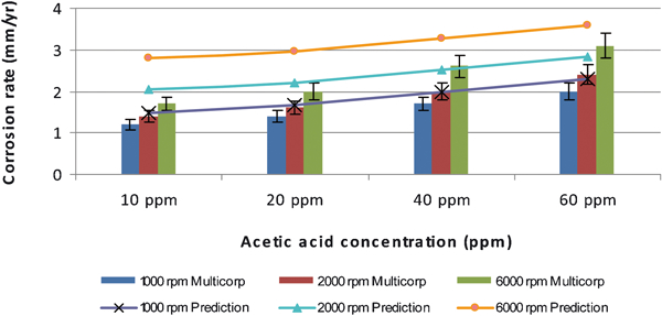
Comparison of prediction equation with experimental data at pH 5, 25°C, 1 bar CO2: error bars represent 10% variant of predicted corrosion rate compared to Multicorp version 4 model
Comparison of prediction equation with experimental data at pH 5, 40°C, 1 bar CO2: error bars represent 10% variant of predicted corrosion rate compared to Multicorp version 4 model
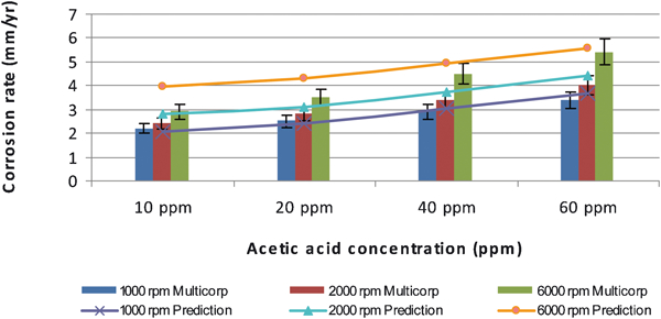
Comparison of prediction equation with experimental data at pH 5, 60°C, 1 bar CO2: error bars represent 10% variant of predicted corrosion rate compared to Multicorp version 4 model
Comparison of prediction equation with experimental data at pH 6, 25°C, 1 bar CO2: error bars represent 10% variant of predicted corrosion rate compared to Multicorp version 4 model
Comparison of prediction equation with experimental data at pH 6, 40°C, 1 bar CO2: error bars represent 10% variant of predicted corrosion rate compared to Multicorp version 4 model
Comparison of prediction equation with experimental data at pH 6, 60°C, 1 bar CO2: error bars represent 10% variant of predicted corrosion rate compared to Multicorp version 4 model
Comparison at pH 5
At 25°C, the prediction equation has a good agreement with the Multicorp model in 10-60 ppm HAc for 1000 and 2000 rev min−1. It is recorded ∼15% of variant from prediction equation as compared to the Multicorp model.
At 40°C, the prediction equation has a good agreement with the Multicorp model. Conservative prediction is observed at 6000 rev min−1, 10 ppm HAc. Under this condition, prediction equation predicts 25% higher than the Multicorp model.
At 60°C, prediction equation predicts lower corrosion rate ∼20% almost for all conditions. However, a good agreement of prediction is observed at 6000 rev min−1, 10 ppm HAc.
Comparison at pH 6
At 25°C, the prediction equation predicts well at 1000 rev min−1 with the presence of 10 ppm HAc. For other conditions, it predicts conservatively at all HAc concentrations.
At 40°C, the prediction equation predicts well for 1000, 2000 and 6000 rev min−1 almost for all HAc. Over prediction, ∼25%, is observed only at 6000 rev min−1, 10 ppm HAc.
At 60°C, the prediction equation has a good agreement with Multicorp model in 40 ppm HAc for all rotation rates. At 10 and 20 ppm HAc, the prediction equation calculate lower corrosion rate than Multicorp model ∼20%, while at 60 ppm, it predicts conservatively for all rotation rates.
In general, validation of prediction equation and Multicorp version 4 model shows a good agreement results. It is observed that ∼20% the differences predicted corrosion rate between prediction equation and Multicorp version 4 model. The worst result is observed at pH 6, 25°C, 6000 rev min−1. Under this condition, prediction equation calculates corrosion rate ∼40% higher than Multicorp model.
Footnotes
Acknowledgements
The authors are thankful to Universiti Teknologi PETRONAS for providing grant and facilities for the research.