
Abstract
Coolant systems in nuclear power plants undergo degradation by various corrosion processes. The carbon steel feeder pipes for the primary heat transport system of pressurised heavy water reactors (PHWRs) undergo extensive wall thinning by a degradation process, known as flow accelerated corrosion (FAC). Flow accelerated corrosion occurs under certain conditions of flow, water chemistry, pipe geometry and material composition. In PHWRs, the outlet feeders carry the heavy water (D2O) coolant, which flows at velocities in the range of 10 to 20 m s−1. The requirement of high flow velocity at high temperature and pressure to simulate the exact service hydrodynamic conditions, and the long time required to enable unambiguous observations regarding the extent of FAC, makes it difficult to undertake this study in the laboratory. This paper presents the design of an FAC module that enables the relatively rapid measurement of FAC to be undertaken in simulated PHWR primary heat transport conditions. The results of corrosion rate measurements and the attempts to explain the results using a computation fluid dynamics model are presented in this paper.
Introduction
Flow accelerated corrosion (FAC) has caused wall thinning in carbon steel piping leading to costly repair or replacement and even rupture of pipes in some power plants.1 Considering its importance to the electrical power industry, efforts are being made to investigate this corrosion phenomenon in detail. Flow accelerated corrosion is a complex process in which mass transport across the metal solution interface is strongly influenced by the velocity of the flowing liquid, temperature, piping configuration and alloying elements of steel used.2–4 The coolant water, which is undersaturated with iron, aided by the turbulent flow conditions prevailing in certain pipe geometries, tries to dissolve the iron/magnetite from steel surfaces, leading to excessive pipe wall thinning. Flow accelerated corrosion has been observed in the primary heavy water coolant system of pressurised heavy water reactors (PHWRs), in the steam water systems of PHWRs, as well as in other reactors and conventional power plants. The wear rate in flow accelerated corrosion varies from a few, to a few hundred, micrometres a year. Thus, the rate of wall thinning in certain locations of the pipe can exceed the corrosion allowance thereby requiring close monitoring of wall thinning and midcourse replacement of the pipes.
The flow accelerated corrosion of the primary heat transport (PHT) system carbon steel feeder pipes is of particular concern to PHWR operators. The carbon steel feeder pipes have been found to undergo significant wall thinning in the external sections of pipe bends and elbows with wall thinning rates as high 150 μm/year reported.5 Recent measurement of wall thinning in Indian PHWRs has also showed signs of flow accelerated corrosion.6 Microscopic examination of the outlet feeder elbow specimens collected from an Indian PHWR indicated the presence of a scalloped surface, which is a clear indication of FAC.
Hence, an attempt is being made to study the role played by various physical, chemical and geometrical parameters in influencing the FAC of carbon steel feeders of PHT system of PHWRs. Studying FAC in the laboratory is difficult for the following reasons:
the requirement of very high coolant velocity at high temperature and pressure
the difficulty in precisely simulating the hydrodynamic conditions of the PHT system in the laboratory experimental facilities
the long period of exposure required to enable unambiguous observations regarding cumulative metal loss due to FAC.
A large number of experimental runs are required to map the entire spectrum of operating conditions prevailing in reactors. Thus, it is essential to devise methods that enable measurement of the flow accelerated corrosion rate (wear rate) of materials in laboratory scale systems within as short a time period as possible.
Usually, the high flow velocity required for this type of study is simulated by using an impinging jet system. Studies have also been carried out elsewhere in stirred high pressure reactors wherein the fluid at the high temperature is stirred at high rotational speed using a shaft that gives the fluid the desired velocity. However, this paper presents the details of an FAC test module designed to carry out measurements of FAC rate in a laboratory high temperature recirculating flow loop system. This experimental assembly enables mapping the variation in corrosion loss along a simulated outlet bend section of feeder pipe of a PHWR and to make a comparison with the corrosion rate obtained in a straight pipe section.
Details of PHWR primary heat transport system outlet feeders
The first bend of the outlet carbon steel feeder pipes of PHWR the primary coolant system have been reported to experience maximum wall thinning by FAC. Hence, the geometry details of the first bend of outlet feeder (e.g. pipe diameter, bend angle and bend radius) were collected. The outlet feeder first bends (of which there are 306) have pipe diameter, bend angle and bend radius that vary, respectively, from 32 to 50 mm, 54 to 76° and 65 to 100 mm. These feeder bends are connected to the outlet ends of the zircaloy pressure tubes that house the zircaloy clad natural uranium fuel bundles. This connection is made by a carbon steel coupling, which is welded to the feeder. The other end of the outlet feeder pipes are connected to the headers which in turn are connected to the steam generators. The heavy water coolant after picking up heat from the nuclear fuel flows out through the outlet feeders, outlet headers, steam generators, inlet headers and then back to the core of the reactor through carbon steel inlet feeders. Thus, the outlet carbon steel feeders of PHWR PHT system are exposed to heavy water coolant (D2O) that flows at a velocity range of 10-20 m s–1 and at high temperatures in the range of 280-292°C. The data provided here represents a typical 220 MWe PHWR.
Chemistry behind FAC
The heavy water coolant in the primary coolant system of PHWRs is maintained at a reducing and alkaline condition by injecting 3-10 mL kg−1 of H2 and by maintaining a certain concentration of LiOD by adding Li2O (pHa 10-10·5). Under high temperature alkaline and reducing chemistry conditions, a two layer magnetite/ferrite forms on the carbon steel components of the system. The inner layer is formed by in situ conversion of iron to magnetite (Fe3O4). A portion of the iron ions released to the coolant is removed by the water purification system within the primary coolant loop. The remaining iron ions released to the coolant is converted to magnetite by the Schikorr reaction, which deposits back as an outer layer of magnetite


However, as mentioned above, certain locations of the feeder elbows are observed to undergo much higher wall thickness losses than predicted.7 The locations where excessive wall thinning takes place have been identified to be the first bend of the outlet feeder which is joined to the outlet of the reactor core. The external section of these outlet bends have been reported to undergo significant wall thinning. The extreme turbulent conditions prevailing in the first bend section of the outlet feeder as well as coolant which is undersaturated with iron when it exits the reactor core, causes the enhanced mass transfer rate leading to excessive wall thinning. The extent of wall thinning in these locations has been found to vary depending upon the coolant conditions, temperature and the distance from the bend.
Design features of laboratory FAC module
Attempts have been made previously to simulate the same hydrodynamic conditions, prevailing in the PHT system in the laboratory. Although system, described elsewhere,8 was able to meet the requirement of high temperature and pressure needed for this study, the three constraints mentioned earlier such as high fluid velocity, requirement of measurement of FAC rate at a specified geometric locations and the long time period involved, were less easily realised. Hence, efforts were made to design an experimental assembly that would overcome all these difficulties and enable relatively rapid measurement of FAC rate of materials under the simulated flow and geometric conditions.
The flow velocity available in the existing high temperature high pressure system was only 3 m s−1. However, the desired velocity could be achieved by fabricating a specimen holder containing a bend pipe assembly having a reduced internal diameter (ID) (∼10 mm). The bend pipe assembly was designed in the form of several ring shaped specimens stacked to form a bend. As the weight of each ring was less than 20 g, it enabled accurate measurement of weight loss by gravimetry (±0·01 mg). Thus, weight changes of the order of few milligrams can be measured accurately, thereby enabling measurement of FAC in short duration experiments. Also, this arrangement enabled the location of the region of maximum attack as the rings in the different locations can be weighed individually. In order to distinguish FAC in bent and straight pipe, a straight section of a pipe was similarly designed by stacking a number of rectangular specimens along the length of another tube and arranging them in a square geometry. The design details of the FAC module comprising both the bend pipe assembly and the straight section are shown in Fig. 1. The ring specimens and the straight specimens were made from the wall of the large diameter ASTM 106 Gr ‘B’ pipe. The ring specimens were numbered sequentially and loaded inside a bent stainless steel pipe of 25 mm diameter. The bend radius was maintained at (D/d ratio) 5·5.
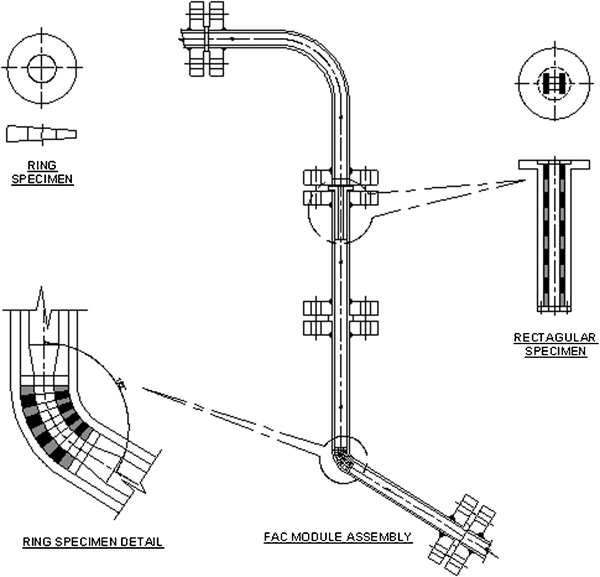
FAC module assembly
A special die was fabricated to bend the pipe to a D/d ratio of 5·5 and bend angle of 58°. The specimens were machined precisely by wire cutting and polished by different grades of silicon carbide paper to an 800 grit finish. After polishing, the specimens were degreased, washed and then mounted on the experimental assembly (FAC module). Ring specimens were kept inside the bend region of the pipe, and the inside diameter of ring specimen was 10 mm was optimised to generate a linear velocity of 13·5 m s−1 for a volumetric flow of 0·063 m3 min−1. The same velocity was generated in rectangular specimen mounted on straight pipe portion by suitable choice of cross-section.
The design parameters for the FAC module include temperature (300°C), pressure (11·03 MPa), diameter (10 mm), length of test section (1·5 m), flow velocity (20 m s−1) and fluid properties (density, viscosity and heat capacity). The FAC module was designed so that the total pressure drop across it is within the total permitted pressure drop of 0·6 MPa. In addition, the FAC module has the following special features:
simple and versatile design that simulates the flow in feeder elbow/pipe of PHWR reactors
mounting and dismantling of the module is easy without disturbing the operation of HTHP loop
direct comparison of corrosion rate between straight and bend pipe is possible as both sections see the same fluid velocity.
Description of high temperature and high pressure system used for FAC study
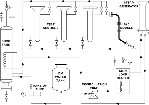
A high temperature high pressure system (HTHP system), established for carrying out nuclear coolant system water chemistry studies and for evaluation of certain engineering parameters, was used in this study after installing the FAC module. The schematic drawing of the HTHP system is given in Fig. 2 and the operating condition of the HTHP system is given in Table 1. It consists of a high pressure high temperature pump, heaters, steam generator with Incoloy-800 tubes, test sections and the associated piping. The main loop heater is the primary heat source of the system and consists of immersion type electrical heaters provided in the main loop heater vessel. The purpose of this heater is to bring up the temperature of the main loop recirculation flow up to 288°C during the start up and then to maintain this temperature. A 15 mm size line takes a flow of 0·003 m3 min−1 to the purification system, to remove any the suspended and ionic impurities in the primary loop. Two filters are provided in the purification system of the loop to remove suspended impurities, etc.
High temperature high pressure (HTHP) loop
System design parameters
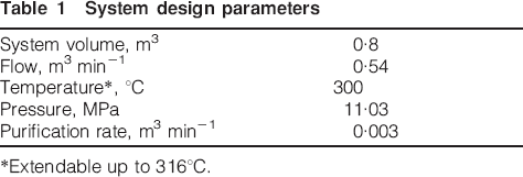
*Extendable up to 316°C.
The system is constructed from stainless steel 316 L with the exception of the surge tank which is made of carbon steel. Any water loss in the system is made up intermittently by pumping demineralised deoxygenated water through the surge tank at a rate of about 0·002-0·003 m3 min−1. The system is operated without a secondary side coolant circuit. Thus, the variation of temperature across the steam generator is very small and iron transport, due to the drop in temperature across the steam generator, is not expected here. However, heat loss by radiation of heat from various components of the system and the heat loss due to the cooling of the water for purification by ion exchange results in temperature difference of about 15°C between the heater outlet and the inlet. Immediately after the heater, a line joins the test section where test specimens of the FAC module are installed for experiments. Thus, it can be assumed that the test specimens see the maximum temperature in the system. Removal of dissolved iron takes place in a purification circuit of with a residence time constant or around 100 min, similar to that of PHWR reactors, and also by iron deposition due to cooling by 15°C in the main system. While calculating the time constant only the volume of the main circulation system (0·44 m3) is taken into account. Thus, undersaturation of iron is ensured in the test section inlet which is a key prerequisite for the study of FAC. The sample holder assembly (Fig. 3) for carrying out FAC study was installed by replacing one of the test sections in this high temperature high pressure system.
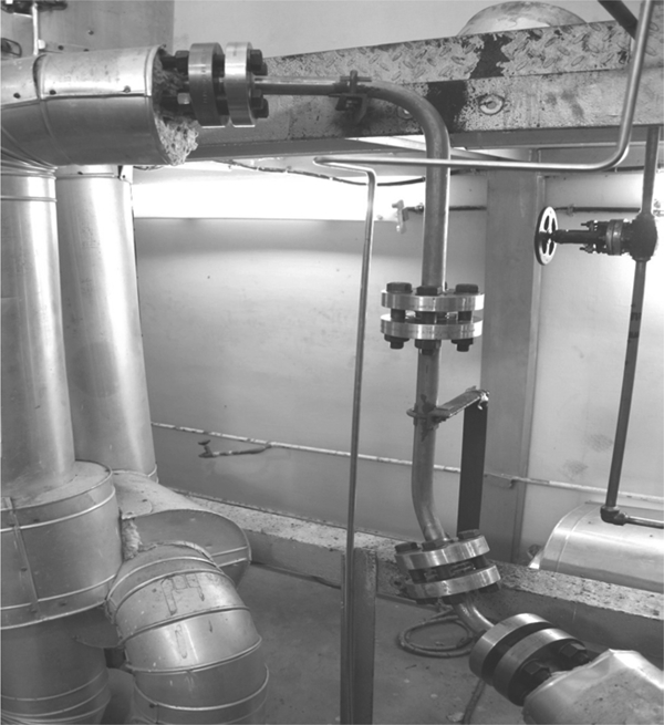
FAC module
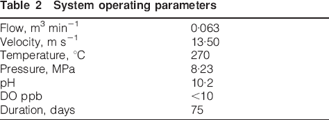
Velocity measurements by ultrasonic flow meter in the FAC module showed a value of 13·5 m s−1. Experiments were conducted under simulated PHWR water chemistry conditions. The chemistry parameters maintained during the experiment are given in Table 2.
System operating parameters
Results
The high temperature high pressure loop, where the FAC module was installed, operated continuously for a period of 75 days. Experiments were conducted at two temperatures, first at 270°C and then at 284°C. After an exposure period of 75 days, the ring specimens and the straight specimens were removed from the system and evaluated for FAC. Results showed measurable weight loss during the period of exposure. In the first trial carried out at 270°C, a comparison of weight loss along the length in the specimen module (indicated as specimen number) is shown in Fig. 4. The figure clearly shows an increased corrosion of about two and half times higher in the bend compared to the straight section. This is a clear manifestation of greater turbulence in the bends causing enhanced metal loss. In the end portions of the bend and also in the end portions of straight sections relatively high corrosion rates were seen. This may be attributed to the change in flow cross-section at entry and exit points of the specimen which may cause complex velocity fields with disturbed flow leading to enhanced corrosion.1,9 In addition, the galvanic effect of carbon steel in contact with stainless steel material might contribute to this excessive corrosion occurring at the exit and entry points.
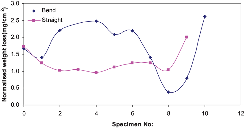
Corrosion rate comparison in bend and straight section (Exp-1)
The loss of material in the second and the ninth and tenth rings correspond to the extremities of the bend pipe which are straight. The weight loss values in those rings matched with that of the specimens taken out from the straight section. Whereas the ring specimen which was in the middle portion of the bend gave significantly higher weight loss compared to the specimens in the straight section. Thus, it is clear that the ring specimens constituting the bend pipe experienced higher corrosion loss.
Second trial
Analysis of the data obtained in the first trial with the FAC module indicated that the number of points corresponding to the extremities of the bend was very few. Hence, the experiment was repeated by adding some more ring specimen at the extremities of the bend so that the length of the linear portion of the bend is extended. The experiment was carried out under same chemistry conditions and for the same duration of 75 days but at a slightly elevated temperature of 284°C. The weight loss measurements carried out on the bend ring specimens and the rectangular straight section specimens gave the expected result. The weight loss data are given in Fig. 5.
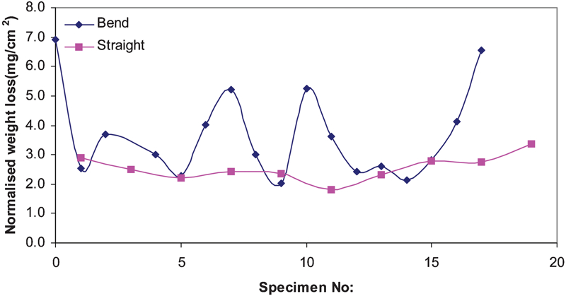
Corrosion rate comparison in bend and straight section (Exp-2)
These results clearly proved that the corrosion in the linear portion at the entry and exit side of the bend is less and the metal loss is equal to the loss observed in straight specimens. In the rest of the bend the corrosion loss is higher as in the previous trial. However, in the middle portion of the bend, again there is a sharp decrease in the metal loss. Such a decrease was not clearly evident in the first trial. Only a small decrease was observed at similar location in the first trial Fig. 4. This result shows that the location of attack depends very much on the dimensions of the bend.
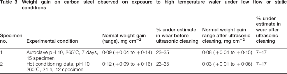
In both the trials, it is assumed that the weight loss observed arises only from the circular inner region which alone is exposed to the fast flowing water. The polished flat portion of the ring surfaces are in contact with the adjacent rings and hence flow of water through these surfaces is not expected. However, leakage of high pressure–high temperature water through the gaps between the two flat portions of the rings could not be prevented. Hence, a thin coating was observed on these surfaces also. It has been observed in several experiments that whenever carbon steel specimens are exposed to high temperature water for duration of up to 15 days under static conditions or at flow velocity less than 2 m s−1 (as observed in the coupons installed during hot conditioning of primary system of PHWRs), even though corrosion is taking place on the carbon steel surface, normally only weight gain of the order of 0-0·12 mg cm−2 is observed. Even in the carbon steel specimens exposed for a prolonged duration of one year in low flow areas of the HTHP loop used in this study, weight gain was observed. The magnitude of weight gain was 0·03 mg cm−2. This gain in weight is due to the net effect of the weight gain due to the oxygen addition to iron by the oxidation process and the weight loss occurring due to the escape of corrosion products. Ultrasonic cleaning of the exposed specimens leads to the release of the loose corrosion products that led to a small decrease in the weight of the specimen thereby bringing the weight of the ultrasonically cleaned magnetite coated specimen close to the initial weight recorded before it is exposed to the high temperature water after polishing. The same should be true in the case of corrosion taking place on the flat surfaces and on the outer circumference surface of the non flow regions of the ring specimen. As only a weight gain is expected in these non-flow regions, the FAC rate calculated based on the over all decrease in weight of the specimens is lower than the actual rate. The error introduced by the corrosion taking place in the non-flow regions of the ring specimen has been estimated to be 23-35%. This error is reduced to 7-17% (Table 3) if FAC rates are calculated with values of weights obtained after cleaning the exposed specimens ultrasonically.
Weight gain on carbon steel observed on exposure to high temperature water under low flow or static conditions
From the weight loss data, it is difficult to say whether the attack takes place on the external or internal wall of the bend. However, velocity profile computed for a 58° bend at 86 bar, 284°C and input velocity of 13·5 m s−1, indicated the possibility of attack taking place at both locations, as shown in Fig. 6.
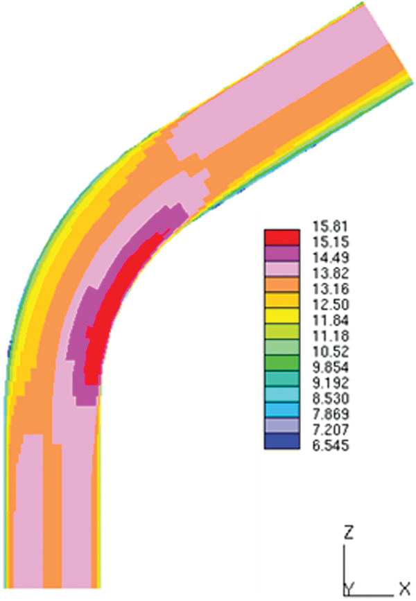
Velocity profile in 58° bend section
Computation of fluid dynamic parameters
Computational fluid dynamic (CFD) calculations were carried out initially to compute the velocity conditions prevailing in the PHT system feeders. These findings, carried out to compute the velocity profile, wall shear stress distribution and turbulent kinetic energy variation for straight pipes and for bend pipes having different bend angles, bend radius and having inner diameter of 50 mm, have already been reported.8 The velocity profile, across the cross-section of a 58° bend having a pipe inner diameter of 10 mm, which was used in these experiments, was computed subsequently and is given in Fig. 6. This figure indicates that the maximum velocity region is observed in the internal wall of the bend.
Velocity profiles were also computed near to the wall of the bent pipe indicating higher near wall turbulence at the internal wall (intrados) as well as the external wall (extrados) near the exit side (Fig. 7). In between the high turbulent regions observed on the intrados and extrados side, a small region of lower turbulence is also indicated in the velocity profile computed near to the wall. These observations indicated that different regions in the bend exhibit difference in their propensity to undergo flow accelerated corrosion. However, it also clearly indicated that the intrados of the bend is more prone to flow accelerated corrosion. This is contrary to the belief that the extrados of the bend undergoes greater wall thinning. Figures 4 and 5 show the corrosion rate variation along the bend especially, and the latter one is a double humped one indicating that the attack takes place on both sides of the bend. However, the weight loss observed in a ring specimen does not provide any clue about the location of attack within the circumference of the ring (intrados or extrados side). Scanning electron microscopy observation of the intrados and extrados side of the ring did not clearly indicate the characteristic features of FAC such as scallops, as the duration of exposure is very low (only 75 days). Computational fluid dynamic modelling of the flow made elsewhere on feeder elbows also indicated that intrados are more vulnerable to attack.10 Thus, these observations indicate that both wall sections of the feeder pipe bend are being thinned by flow accelerated corrosion. Usually it is difficult to measure the wall thickness on the inner bend side. Hence the residual life time evaluation made on external bend wall thickness may yield a misleading picture. Modification of the experimental assembly to observe the difference in the corrosion behaviour of the intrados and extrados of the bend using thin layer activation is in progress.
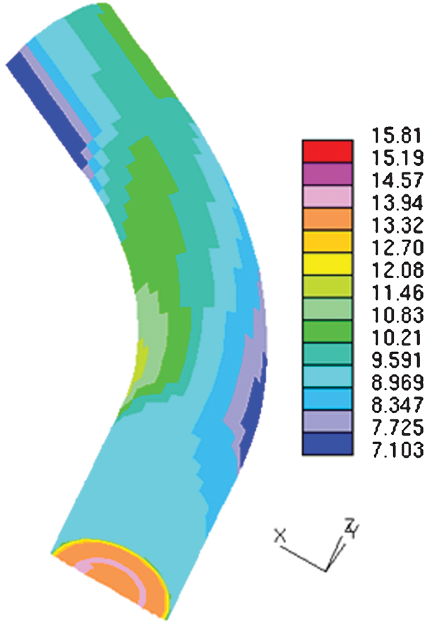
Near wall velocity profile in 58° bend
Conclusions
1. An FAC module for the measurement of FAC rates at different locations in a bend pipe under simulated hydrodynamic conditions prevailing in the feeders of the primary heat transport system of pressurised heavy water reactor has been designed.
2. Measurements carried out with this FAC Module confirmed that the rate of corrosion in a bend is higher than the rate in straight pipe and in the straight section of the bend pipe ends.
3. The corrosion rate varies along the distance in a bend pipe which could be correlated to the variation in the fluid flow velocity and wall shear stress obtained by CFD.
4. This FAC module enables measurement of the rate of FAC of structural materials in a relatively short time period.
Footnotes
Acknowledgements
The authors would like to thank Dr P. Chellapandi, P. Selvaraj, Dr K. Velusamy and K. Natesan of Reactor Group, IGCAR, Kalpakkam for the useful discussion and co-ordination in CFD work. The authors also thank the Engineers of HTHP loop: Y. V. Harinath, P. J. George, R. Jeeva, N. Jayaram, M. Mukundan, K. Amit and all the operators for valuable contribution towards FAC experiments.