
Abstract
A conversion coating treatment using cerium salts was developed for the surface sealing of electroless nickel–phosphorus (Ni–P) coatings on carbon fibre reinforced aluminium (Cf/Al) composites. The corrosion resistances of uncoated and coated materials (i.e. the Ni–P coating, the Ce conversion coating and Ce sealed Ni–P coatings) were evaluated in 3·5 wt-%NaCl solution using potentiodynamic polarisation and electrochemical impedance spectroscopy. Ce sealed Ni–P coating showed the highest corrosion resistance and clearly improved the overall corrosion resistance of Cf/Al composites. Thus, the Ce sealed Ni–P coating had no obvious microcracks that were generally evident in the more conventional Ce conversion coatings. This is presumed to occur because the electroless nickel surface is relatively homogeneous, compared with the Cf/Al composite surface on which different local coating thicknesses would encourage increased microcrack formation. X-ray photoelectron spectroscopy analysis showed that the Ce conversion coating mainly contained both Ce3+ and Ce4+ species; however, Ce4+ species were the dominant oxidation state on Ce sealed Ni–P coatings.
Introduction
In light of their excellent mechanical properties, such as low density, increased specific strength and modulus, carbon fibre reinforced aluminium alloy (Cf/Al) composites are considered as ideal structure materials; however, these materials show a poorer corrosion resistance than monolithic Al alloys. This is because in Cf/Al composites, the Al matrix and the carbon fibres create a galvanic couple where the carbon is invariably the cathode.1,2 One way to improve the performance of a material is to use a surface treatment, such as a conversion coating, which is commonly applied to many materials. Traditionally for aluminium alloys, the most popular and effective conversion coating process is based on the immersion of specimen in solutions containing chromate ions. However, the use of chromate is being progressively restricted due to the high toxicity of the hexavalent chromium compounds.3 In seeking alternatives to chromate conversion coating, non-chromate solutions have recently been developed based on the use of rare earth salts such as cerium or lanthanum.4,5
Electroless nickel coatings are preferred in many applications because of their generally excellent corrosion resistance.6 Electroless nickel deposition is a self-initiating, autocatalytic process in which complexed nickel ions in an aqueous solution are chemically reduced and plated on a catalytically active substrate with continued Ni deposition through the catalytic action of the deposit itself. Using sodium hypophosphite reducing agent, the deposited layer always contains phosphorus in addition to the nickel; thus, in acetate based electroless nickel baths with hypophosphite reducing agent, the resulting deposit will be a nickel–phosphorus (Ni–P) alloy.7 In some cases, a post-treatment sealing process for Ni–P coatings is used that generally contains hexavalent chromium. Hence, an intense research effort is underway for their replacement.
Rare earth chlorides have been tested as corrosion inhibitors for Al alloys, such as AA 5083,8 AA 7075,9 AA 8090,10 AA 606111 and AA 2024,12 and act as cathodic inhibitors.13,14 In a series of papers,15–17 several researchers have demonstrated that conversion coating treatments with an aqueous solution of rare earth salts, especially cerium, effectively inhibited corrosion. These studies revealed that corrosion protection could be attributed to the formation of a hydrated rare earth oxide film over the cathodic sites on the metal surface. However, relatively little research is reported on the use of cerium post-treatment for Ni–P alloys.18
The goal of this paper was to investigate the post-treatment of electroless Ni–P coatings with a cerium containing solution (Ce sealed Ni–P coatings), in order to inhibit the corrosion of Cf/Al composites. The detailed microstructures of electroless Ni–P coatings, cerium conversion coatings and Ce sealed Ni–P coatings were characterised using scanning electron microscopy (SEM), energy dispersive X-ray (EDX) and X-ray photoelectron spectroscopy (XPS), while electrochemical measurements were employed to analyse the corrosion behaviour of the Cf/Al composites.
Experimental
Materials
M40 carbon fibres were employed to reinforce AA 6061 series. The Cf/Al composite samples were made by squeeze casting, including infiltration of the carbon fibre preform by molten 6061 Al under a pressure of ∼100 MPa. The 6061 Al was employed for matrix and has a nominal composition in wt-%: 0·30Cu–1·00Mg–0·70Fe–0·60Si–0·15Mn–0·20Cr–0·25Zn–0·15Ti, with the remainder Al.
Coatings and sealing
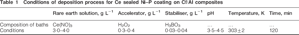
In order to form a Ni–P coating, a pretreatment process is often required to obtain the necessary catalytically active surface. Processes such as zincate treatments, noble metal activation, etc., have been used for surface activation before depositing Ni–P coatings.19 In this paper, the specimens were degreased in an aqueous solution containing Na3PO4 (30 g L−1), Na2CO3 (25 g L−1) and Na2SiO3 (8 g L−1) at 70-85°C for 2-5 min. The specimens were then washed using ultrasonic treatment in distilled water. The zincate treatment solution conditions were as follows: NaOH (120 g L−1), ZnO (50 g L−1), KNaC4H4O6 (50 g L−1), FeCl3 (2 g L−1) and NaNO3 (1 g L−1) at 20-25°C. The electroless nickel plating solution consisted of NiSO4.7H2O (20-30 g L−1), C3H6O3 (20-30 g L−1), C6H8O7.H2O (10-15 g L−1), CH3COONa (20-30 g L−1), NaH2PO2.H2O (20-30 g L−1), pH 4-6, at 70-80°C. The treatment conditions for cerium sealing of the electroless nickel coating is shown in Table 1. A single cerium conversion coating on the surface of Cf/Al composites was also employed in the absence of the Ni–P coating, with similar treatment conditions. Microstructural examination of the Ni–P coating, Ce conversion coating and Ce sealed Ni–P coatings was investigated using SEM, energy dispersive spectroscopy (EDS) and XPS.
Conditions of deposition process for Ce sealed Ni–P coating on Cf/Al composites
Electrochemical testing
Before each electrochemical experiment, the surfaces of the specimens were degreased with acetone and then rinsed in distilled water before being used. The corrosion behaviour of the treated substrates was evaluated under immersion in sodium chloride using the potentiodynamic polarisation and electrochemical impedance spectroscopy (EIS) methods. All the experiments were conducted at room temperature (25°C) using samples or area 1 cm2. An Ag/AgCl electrode was employed as the reference electrode, and all the potential data presented in this paper are referred to this potential. All electrochemical experiments were performed after stabilisation of open circuit potential (OCP). Electrochemical impedance spectroscopy measurements were performed by applying a sinusoidal potential perturbation of 10 mV at OCP. The impedance spectra were measured with a frequency sweep from 100 kHz to 10 mHz in logarithmic increment.
Results and discussion
Microstructure and EDS
Figure 1a shows a SEM image of the surface of the uncoated Cf/Al composites; the carbon fibres and Al alloy can be seen to be firmly adherent. Figure 1b shows the Ce conversion coating, Fig. 1c shows the Ni–P coating and Fig. 1d shows the Ce sealed Ni–P coating. It was found that, in the absence of the Ni–P coating, the Ce conversion coating covered the whole surface of Cf/Al composites as oxidised islands, but with some microcracks in the coating. The Ce sealed Ni–P coating has no obvious microcracks.
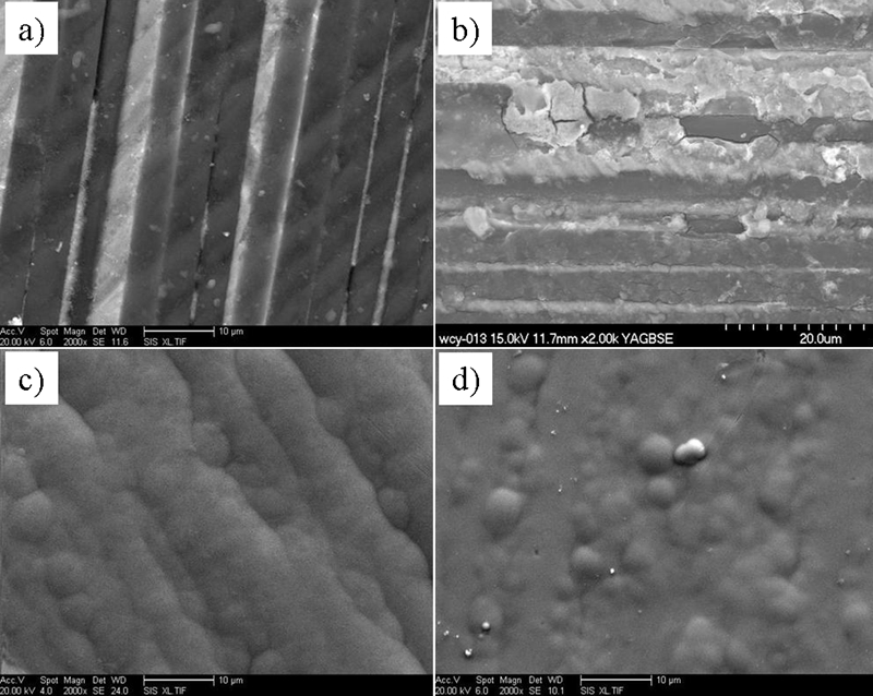
Surface morphology of Cf/Al composites and their coatings
The distributions of chemical elements in the Ce conversion coating, Ni–P coating and Ce sealed Ni–P coating are shown in the EDX analyses in Figure 2 Figure 3 Figs. 2-4 respectively. Figure 2 shows that the C and Al signals are still evident in the Cf/Al composites; however, Ce and O are distributed as major constituents throughout the Ce conversion coating. Figure 3 shows the elemental composition for the Ni–P coatings. Elemental maps of the Ce sealed Ni–P coating show that Ni, Ce and O distributions are relatively evenly distributed with some local nodules of cerium and oxygen coenrichment. Importantly, in Fig. 4, the Cf/Al composites are completely covered by the Ni–P coating, and no evidence of significant aluminium or carbon is seen.
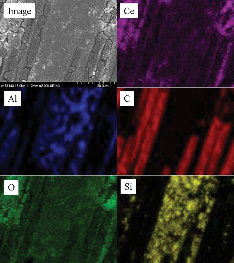
Energy dispersive spectroscopy elemental maps for Ce conversion coating only
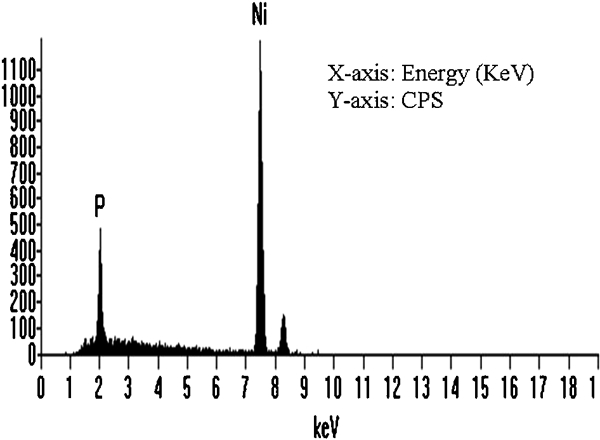
Spectra (EDS) for Ni–P coating
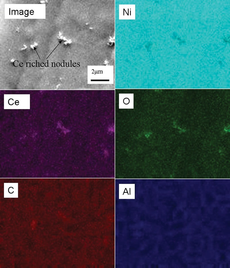
Energy dispersive spectroscopy elemental maps for Ce sealed Ni–P coating
In previous investigations,20,21 the rare earth element is preferentially deposited over cathodic areas, probably as Ce (Ce3+ and Ce4+) hydroxide/oxide, because the precipitation process is driven by the electrochemical potential differences on the substrate surface. Strongly cathodic areas on the composite surface have different deposition rates, with different coating thicknesses, leading to the final microstructure. Owing to inhomogeneity of the Cf/Al surface, a different deposition rate of the Ce conversion coating would be expected on the carbon fibres compared with the substrate leading to microcrack in the coatings.22 However, for the Ni–P coated substrate, the relatively homogeneous surface leads to a more even, and probably thinner, Ce rich film that, consequently, lack microcracks.
X-ray photoelectron spectroscopy analysis
With the aim of analysing the Ce products formed, an XPS study was performed on the surfaces of the Ce conversion coating on the Cf/Al substrate and Ce sealed Ni–P coating on the substrate. Figure 5 shows the high resolution spectra corresponding to Ce3d for the Ce conversion coating formed directly over the composite material. Yu and Li23 postulated that, initially, hydroxide is formed and later, during the drying step, is transformed to several compounds, such as Ce2O3, CeO2 and CeO2.xH2O. These immersion treatments produced Ce3+ and Ce4+ coatings with a good degree of adherence. A consistent result is confirmed from high resolution XPS spectra of Ce3d obtained for the Ce conversion coating on the Cf/Al composite surface. In this work, the Ce conversion coating mainly contained both Ce3+ and Ce4+ species; therefore, it is reasonable to think that the Ce conversion coating core is formed by Ce3+ species and the external Ce conversion coating by mixture of Ce3+ and Ce4+ species. Different authors have confirmed the presence of Ce3+ in the Ce conversion coatings together with a quantity of Ce4+, probably related to the atmosphere exposition, since Ce3+ is not stable in contact with O2 and would automatically convert to Ce4+. Therefore, the Ce conversion coating core is probably formed as Ce(OH)3/Ce2O3 with an external film of CeO2/Ce(OH)4.24
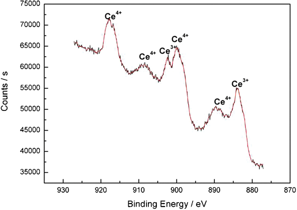
Ce3d XPS spectra of Ce conversion coatings
Figure 6 shows the high resolution spectra corresponding to Ce3d for Ce sealed Ni–P coatings. Kobayashi and Fujiwara18 proposed that Ce rich films on nickel predominantly contain Ce4+ species. In this work, the measured peaks at binding energies of 881·8, 900·6, 888·7, 907·2, 891·2 and 916·5 eV were assigned to Ce3d characteristic peaks corresponding to Ce4+ state, in good agreement with the reported spectra.18,23,24 Characteristic peaks corresponding to Ce3+ state appeared to be lacking on the Ce sealed Ni–P coatings after the same sampling time interval as the previous data. These results indicate that Ce4+ was the dominant oxidation state on Ce sealed Ni–P coatings.
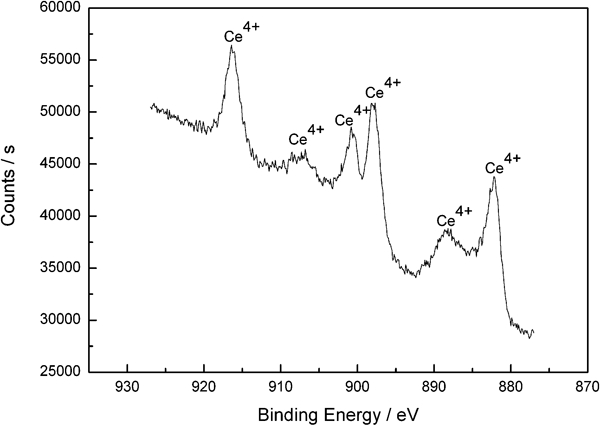
Ce3d XPS spectra of Ce sealed Ni–P coatings
Electrochemical results
The behaviours of uncoated composite and composites with different coatings in 3·5 wt-%NaCl solution were evaluated by potentiodynamic polarisation and EIS. The potentiodynamic polarisation curves are shown in Fig. 7. The anodic portions for the substrate with and without the Ce conversion coating were similar, whereas the cathodic portion was shifted towards the left (i.e. to lower current densities), indicating a decrease in the overall corrosion rate. In contrast, the electroless nickel coated substrate had a nobler potential E corr and showed substantial passivity, which was enhanced considerably by the Ce sealed Ni–P, indicating that this coating provides the best corrosion performance.
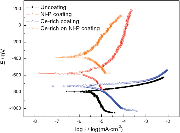
Potentiodynamic polarisation curves for different coatings
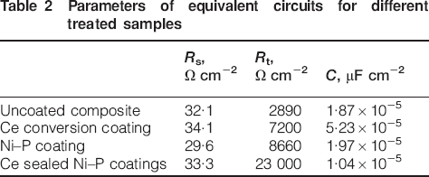
Figure 8 shows the electrochemical impedance Nyquist diagrams for the four materials, which all show a generic single semicircle. To include the effects observed at both high and low frequencies in an equivalent circuit would result in unnecessary complications, and therefore, the authors did not attempt it, and hence, the simple equivalent circuit model is shown in Fig. 9.25 The values of R t and C for the uncoated and coated specimens are listed in Table 2. The Ce sealed Ni–P coating has the highest value of R t (23 000 Ω cm−2), while the uncoated sample has the lowest value of R t (2890 Ω cm−2), which confirms the substantial improvement in corrosion resistance of the Ce treated Ni–P coatings. The Ce conversion coating with microcracks should have larger surface areas than the others, and this is reflected in the higher measured capacitance (5·23×10−5 μF cm−2).
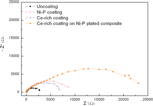
Nyquist diagrams for different coatings
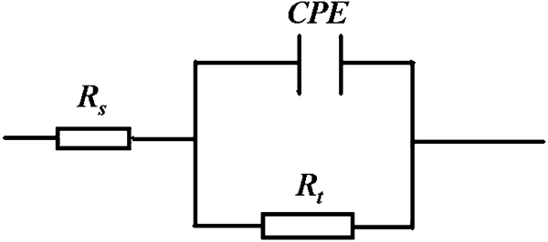
Equivalent circuit diagram for Fig. 8
Parameters of equivalent circuits for different treated samples
From the above research on Cf/Al composites, the corrosion performance of the uncoated material can be substantially improved by Ce conversion coating and by Ni–P plating. However, the best performance is using a Ce sealed Ni–P coating, which has the highest corrosion resistance.
Conclusion
Electroless plating Ni–P coating, Ce conversion coating and Ce sealed Ni–P coating were employed to improve the corrosion resistance of a Cf/Al composite alloy. The Ce sealed Ni–P coating has clearly improved the corrosion resistance of the Cf/Al composites; this coating has none of the microcracks, which are present in Ce conversion coatings on the substrate in the absence of the electroless nickel. Owing to the inhomogeneity of the material surface, resulting in locally different thicknesses of the Ce film, microcrack formation is present on the Cf/Al composite surface. The results of XPS analysis showed that the Ce conversion coating mainly contained both Ce3+ and Ce4+ species, but Ce4+ species were the dominant oxidation state on the Ce sealed Ni–P coatings.