
Abstract
Vapour deposited coatings usually contain microscopic defects, which can provide corrosive media with easy access to the substrate. Consequently, formation of galvanic cells between the coating and substrate can initiate localised corrosion at the defective sites. In this study, TiN coatings were deposited on mild steel (MS) and stainless steel (SS) substrates using a cathodic arc technique. A post-deposition treatment with polymethyl methacrylate (PMMA) was applied to both TiN/MS and TiN/SS systems to block access of corrosion media to the substrates through the coating defects. The as deposited and PMMA treated coating systems were subjected to electrochemical tests in 3·5%NaCl solution. Potentiodynamic polarisation testing results indicated that the PMMA treatment led to a higher corrosion potential and a lower anodic current density for both TiN/MS and TiN/SS systems when compared with their as deposited counterparts. Extended exposure in 3·5%NaCl caused severe localised corrosion in the as deposited TiN/MS due to the presence of coating defects and poor corrosion resistance of the substrate. Electrochemical impedance spectroscopic measurements demonstrated that the PMMA post-deposition treatment significantly improved corrosion resistance of both TiN/MS and TiN/SS systems by effectively sealing the open voids or pores associated with the coating defects.
Introduction
Hard coatings, especially transition metal based nitride coatings, have been extensively used to protect metal workpieces from erosive attack and wear damage due to their excellent tribological properties.1–3 Furthermore, they are quite inert to most chemicals and, therefore, are able to provide corrosion protection to less noble metals such as steels. However, physical vapour deposited coatings have inherent microscopic defects, such as pinholes, pores and growth defects.4–7 These defects can provide access for corrosive media to reach substrates and consequently initiate localised corrosions at the defective sites. Such localised corrosion may sometimes result in more severe damage than that occurring on a bare metal substrate.8,9 Approaches proposed to alleviate the detrimental effects of the coating defects include increasing coating thickness to reduce permeable defect densities,10,11 using multilayering coating structure to interrupt columnar growth12 and increasing substrate bias to densify the coating structure during coating process.13,14 Adding a dense noble interlayer as a barrier between substrate and hard coatings could also protect the substrate from corrosive attack.15
In this study, TiN coatings were deposited on mild steel (MS) and 17-4PH stainless steel (SS) substrates using the cathodic arc technique. Polymethyl methacrylate (PMMA, [C5O2H8]n) post-deposition treatment was used to physically clog voids or open pores in the coatings. PMMA was selected based on its low water absorption rate and good resistance to acids, alkalis and weathering16 and, most importantly, its ability to fill nanoscaled pores through in situ polymerisation of monomer PMMA.17,18 A potentiodynamic polarisation technique and electrochemical impedance spectroscopic measurements over extended exposure to salt solution were used to investigate the corrosion behaviours and the effectiveness of PMMA treatment of the TiN/MS and TiN/SS systems.
Experimental
TiN coatings were deposited on polished AISI 1040 MS and 17-4PH SS discs of 1·6 cm in diameter using a Metaplas MZR-304 unfiltered cathodic arc coater. Before the deposition, the substrate surface was ion cleaned using arc enhanced glow discharge with a titanium cathode. Four metallic Ti cathodes and N2 gas were used to deposit TiN coatings at a chamber pressure of 8×10⁻³ mbar for a total of 480 Ah. During the deposition stage, the substrates were negatively biased at a voltage of 200 V and heated to ∼400°C using an electrical resistance heater. Several TiN coated samples were post-deposition treated with a PMMA solution, which consists of 16·6 wt-% PMMA, 78·4wt-% methyl methacrylate and 5 wt-% benzoyl peroxide. The samples were ultrasonically cleaned with methanol alcohol, air dried and immersed in the PMMA solution for 24 h at ambient temperature to ensure full penetration of the solution into the open pores or voids of the coatings. The treated specimens were then cleaned with soft fresh tissues to remove residual PMMA solution on the external surface and cured under ultraviolet radiation for 8 h. During curing, PMMA was synthesised by radical polymerisation of MMA in the presence of benzoyl peroxide, which acted as a radical initiator.17 The TiN coating layer in this study is only 3·7 μm in thickness; therefore, benzoyl peroxide is able to absorb enough radiation for the sufficient polymerisation of the MMA filled in the voids or pores.
Electrochemical tests were performed at 22°C on a surface area of 78·5 mm2 in a 3·5%NaCl aqueous solution using a Gamry electrochemical testing system. The traditional three-electrode system was employed, wherein the saturated calomel electrode (SCE) acted as a reference electrode and a graphite bar as a counter electrode. The polarisation curves were measured at a scan rate of 1 mV s−1, starting from an initial potential of −0·3 V versus the open circuit potential of the coating. The electrochemical impedance spectroscopy (EIS) technique was employed to reveal changes in corrosion performance with longer exposure times. Electrochemical impedance spectroscopy spectra were measured with an alternating current (ac) signal of 10 mV peak to peak in amplitude superimposed on the open circuit potential. The frequency range of the ac signal was from 300 kHz to 10 mHz.
Results and discussion
Surface morphologies of as deposited and PMMA treated TiN coatings
Of particular interest among the SEM observation is the presence and morphology of surface defects. In all the coating/substrate systems evaluated, ‘cauliflower’-like nodular defects were observed (Fig. 1a and b). An apparent separation was found between nodules and the surrounding coating. The cross-sectional view in Fig. 1c shows that the nodules are porous, especially at the lower section towards the substrate. These nodules, having the same composition as the bulk coating, are growth defects formed mainly on the metal rich droplets (appearing white under backscatter electron mode, Fig. 1c) ejected from the cathode arc spot during coating deposition. The droplets landing on the substrate acted as preferred nucleation sites for coating to grow at a faster rate than the bulk deposit and thus caused shadowing effects on the adjacent areas. When the coating continues to grow, a gap or weak bonding will form between the nodules and the surrounding coating.19,20 Owing to either high internal stresses21 or external forces, some of the nodular particles can detach from the coating, leaving craters on the surface. The crater surfaces, as shown in Fig. 1d, are covered by a thin layer of the TiN coating with a rough and porous morphology. The density of the nodular particles larger than 1 μm in diameter was measured at four randomly selected areas under SEM and found to be in the range of 2200−2700 mm−2. The nodules and craters left by the detached nodules can act as potential sites for localised corrosion.
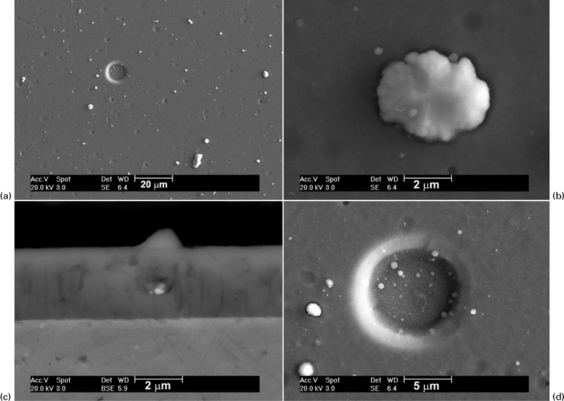
Images (SEM) of as deposited TiN coating showing presence of defects
Scanning electron microscopy examination of PMMA treated samples revealed no presence of PMMA on the coating surface, except at areas surrounding the nodules or on the crater surface. Figure 2a clearly shows the gap between a nodule, and the coating bulk is covered by a thin layer of PMMA; PMMA appears dark under backscattered electron mode (Fig. 2b) due to the lower atomic masses of C, H and O. A strong carbon peak accompanied by an oxygen peak in the energy dispersive spectroscopy (EDS) spectrum (Fig. 2c) further confirmed the presence of PMMA. The Ti and N peaks shown in the spectrum were due to the underlying coating. It was also observed that the crater areas left by detached nodules were covered by a thin and dense layer of PMMA (Fig. 2d). As indicated in the section on ‘Experimental’, before ultraviolet curing, the specimens were cleaned with soft fresh tissues to remove the residual PMMA solution from the external surface after being immersed in PMMA solution. Energy dispersive spectroscopy analysis performed at areas away from the nodules or craters showed exactly the same EDS spectrum as the as deposited coating surface, containing Ti and N peaks only. These observations indicated that the PMMA treatment successfully covered defect related areas (nodule detached crater surface and areas surrounding the nodules) while leaving the rest of the coating surface free of PMMA.
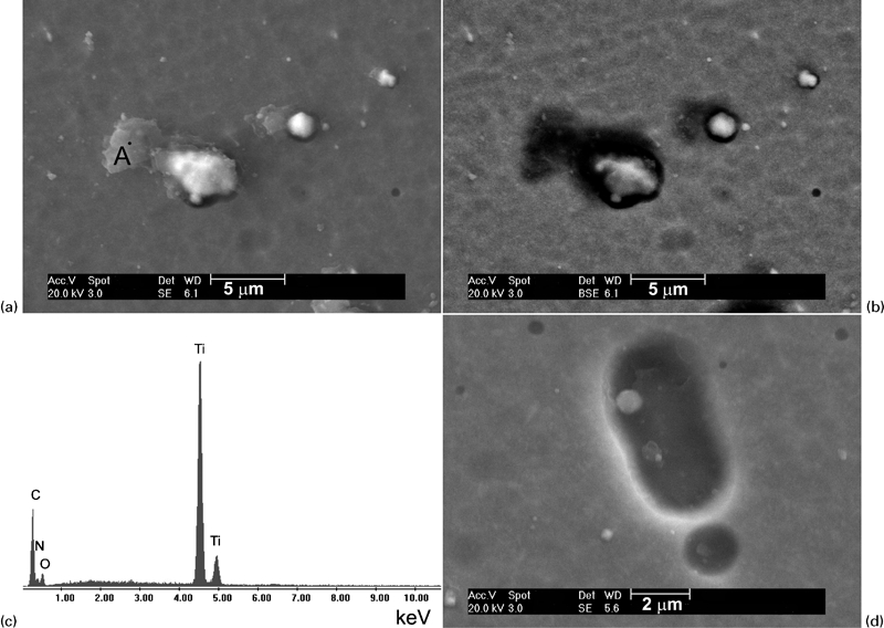
Images (SEM) showing both gap areas surrounding nodules
Potentiodynamic polarisation measurements
The potentiodynamic polarisation curves of the MS substrate, as deposited and PMMA treated TiN/MS systems are presented in Fig. 3. While the as deposited TiN/MS system demonstrated a higher corrosion potential than that of the MS substrate, the PMMA treated TiN/MS system exhibited a further increase in corrosion potential. As anticipated, the anodic current density of the MS substrate increased drastically with the anodic polarisation, showing an active dissolution mode. However, the anodic current density of as deposited TiN/MS was much lower than that of the substrate and increased slightly as the anodic polarisation increases. The PMMA treated TiN/MS demonstrated the lowest anodic current density among the three samples; a slight increase in anodic current density was observed with increasing polarisation.
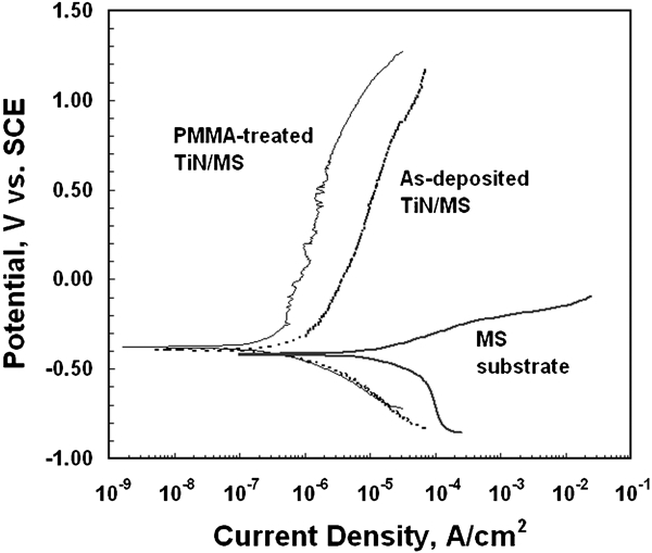
Potentiodynamic polarisation curves of mild steel substrate, as deposited and PMMA treated TiN/MS systems measured in 3·5%NaCl solution
Figure 4 presents the polarisation curves of 17-4PH SS substrate, as deposited and PMMA treated TiN/SS systems. The SS substrate demonstrated a narrow passive range with corrosion and pitting potentials of −374 and 26 mV (versus SCE) respectively. When compared to the SS substrate, the as deposited TiN/SS system had a slightly higher corrosion potential and a comparable pitting potential but a lower anodic current density in the passive range. The PMMA treated TiN/SS revealed the lowest anodic current density and the highest corrosion potential among the three samples.
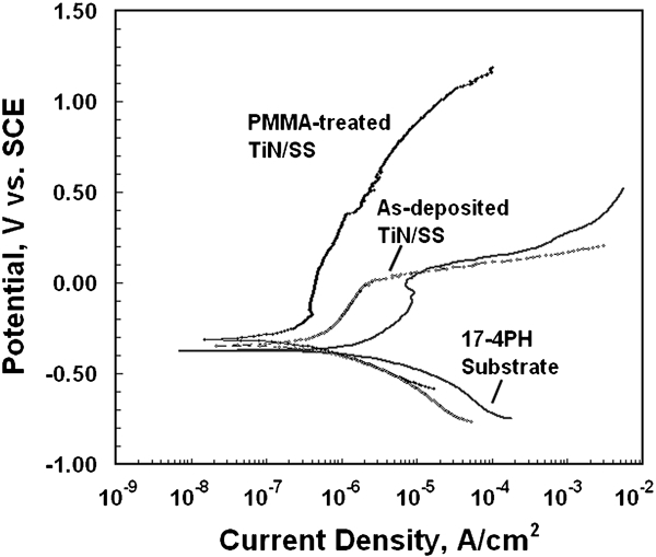
Potentiodynamic polarisation curves of 17-4PH stainless steel substrate, as deposited and PMMA treated TiN/SS systems measured in 3·5%NaCl solution
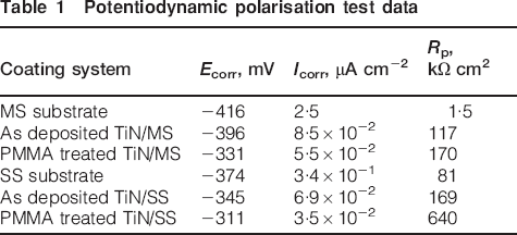
The potentiodynamic polarisation test data are summarised in Table 1. It is clear from this table that the TiN coating improved the corrosion resistance of the substrates, and PMMA treatment further enhanced the corrosion performance of the coated systems. However, the potentiodynamic polarisation measurement, a quick but usually destructive technique, is not capable of providing information with regard to the long term evolution in corrosion performance of a coated system. Therefore, additional analysis with EIS measurement was carried out in this study to investigate the long term performance of the coated system.
Potentiodynamic polarisation test data
Electrochemical impedance spectroscopy measurements
Electrochemical impedance spectroscopy technique is sensitive to changes in the resistive–capacitive nature of electrochemical interface and can be conducted non-destructively.22 As such, EIS has been extensively used to study coating degradation in corrosive environments.23 In this study, EIS spectra were measured after various immersion times to investigate the changes in corrosion performance with exposure time in NaCl solution. The impedance spectra were presented in the form of Nyquist plots composed of real and imaginary components of the obtained impedance values.
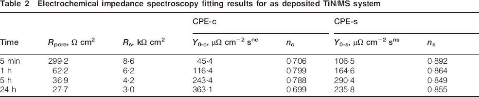
The evolution of the EIS spectra of the as deposited TiN/MS system is shown in Fig. 5a. The impedance arcs diminished rapidly with exposure time. The impedance modulus at 10 mHz decreased from 6·4 to 2·7 kΩ cm2 as the immersion time changed from 5 min to 24 h. This dramatic decrease in impedance modulus in general indicates a rapid deterioration of the coated system in corrosion protection. An equivalent circuit (EC) (Fig. 5b), which has been widely used for corroding coated metal to describe localised corrosion at coating defective sites,24,25 was employed to fit the EIS spectra in Fig. 5a. In this circuit, R e and R s represent the resistance of electrolyte and charge transfer resistance respectively, while R pore is the pore electrical resistance of the coating, which is reversely proportional to the area of the surface defects (pores). Two constant phase elements (CPE), CPE-c and CPE-s, represent non-ideal capacitances of the coating and the double layer. The admittance of a CPE equals Y 0(jω)n, where Y 0 and n are the admittance constant and empirical exponent of the CPE respectively. Table 2 presents the fitted results for the EIS spectra measured at various immersion times. It is clearly seen from this table that pore resistance of TiN/MS system decreased with time, indicating the corrosion progression of the MS surface area. Furthermore, the R s value decreased from 8·6 to 3·0 kΩ cm2 after 24 h immersion. Several circular spots stained with corrosion products, as indicated by the arrows in the optical micrograph (Fig. 6a), started to appear after only 1 h of exposure. After EIS testing, the sample was subjected to thorough SEM/EDS examinations. It was observed that while the majority of the exposed TiN/MS surface area looked intact from corrosion, the sample experienced localised corrosion at various locations associated with the coating defects. Corrosion products were observed around defects with varying severity of corrosion. Traces of corrosion products were observed around some nodular defects (Fig. 6b), while at other defect location, such as the stained spots in Fig. 6a, significant amounts of corrosion products were deposited around the ‘pit mouths’ with similar size to the nodular defects (Fig. 6c). These corrosion product deposits consist of Fe and O (shown in the EDS spectrum of Fig. 6d measured near the pit mouth in Fig. 6c, indicating the corrosion attack of the steel substrate material. These observations clearly demonstrated that the corrosive media had penetrated through the permeable pores or open voids and established galvanic corrosion cells between the exposed substrate surface and the TiN coating. As the MS substrate does not have the ability to form a passive film, corrosion on MS substrate usually takes the form of anodic dissolution.26 Furthermore, due to the large ratio of cathode to anode areas, the corrosion process of the exposed substrate is fast, and the volume expansion associated with the formation of corrosion products may induce enough stress to cause coating fracture and subsequently large pit opening.
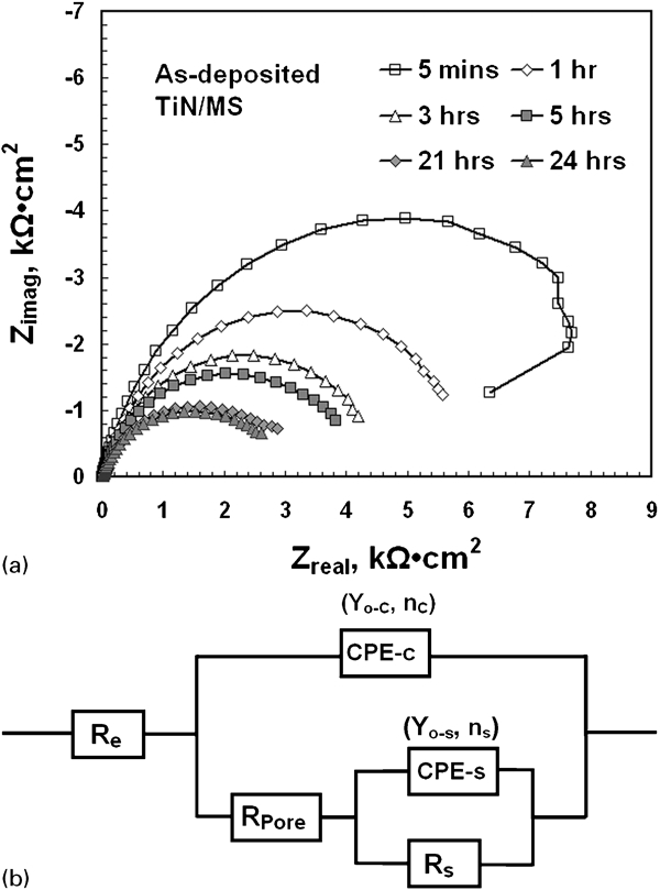
Nyquist plots of as deposited TiN/MS system
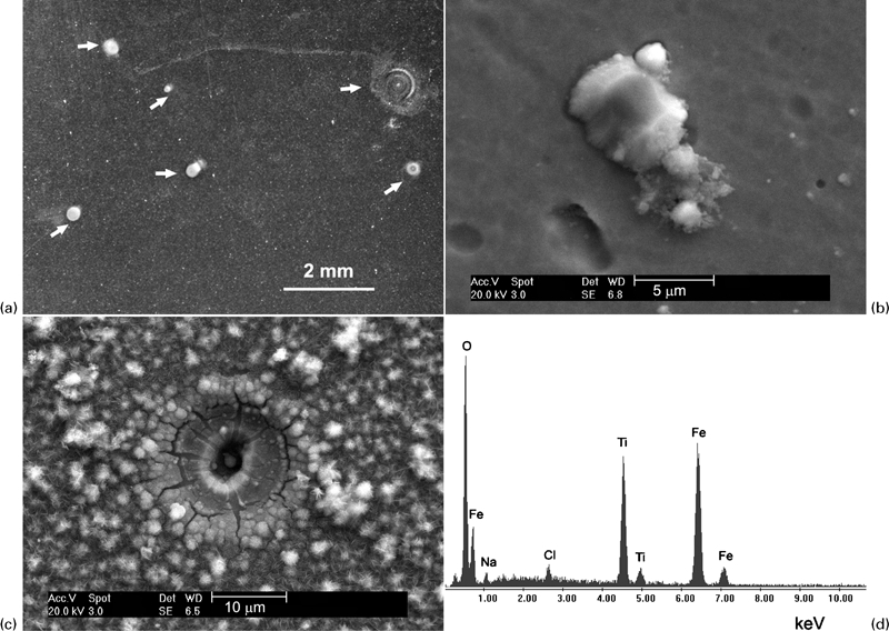
a optical micrograph and b, c SEM images show corroded as deposited TiN/MS surface, energy dispersive spectroscopy spectrum in d indicates that corrosion product deposits near pit mouth in c consist of Fe and O
Electrochemical impedance spectroscopy fitting results for as deposited TiN/MS system
The EIS spectra of the as deposited TiN/SS systems are presented in Fig. 7a. The impedance spectra assume an arc shape, illustrating significantly larger impedance values at a low frequency in comparison with the impedance values of the TiN/MS counterpart. The appreciably larger impedance arcs implied that corrosion of the TiN/SS system was not as severe as the TiN/MS system. Furthermore, visual examination did not reveal any rust spots for the TiN/SS system up to an immersion period of six days. An EC (Fig. 7b), which was proposed for a coated SS system,26 was used to fit the EIS spectra of the as deposited TiN/SS system, where element R e is electrolyte resistance and R p is the polarisation resistance of the coating. A CPE and a diffusional impedance element (Warburg impedance W) were incorporated into the EC to accommodate non-ideal electric behaviour. The decrease in R p over the first 48 h, as shown in Table 3, indicates slight deterioration in corrosion resistance of the TiN/SS system as the corrosive media penetrate to the SS substrate through the coating defects. Scanning electron microscopy examinations after the exposure showed that the coating surface remained similar to that before immersion (Fig. 8a), except that traces of corrosion products were observed around several defects (Fig. 8b). In contrast to the severe localised corrosion observed in the TiN/MS system, the SS substrate in the TiN/SS system has the ability to form a dense passive film offering better protection to the underlying material.
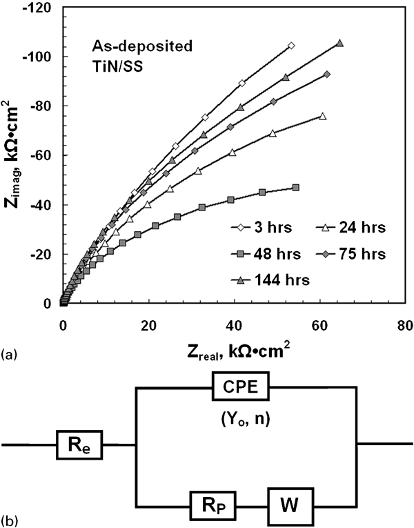
Nyquist plots of as deposited TiN/SS system
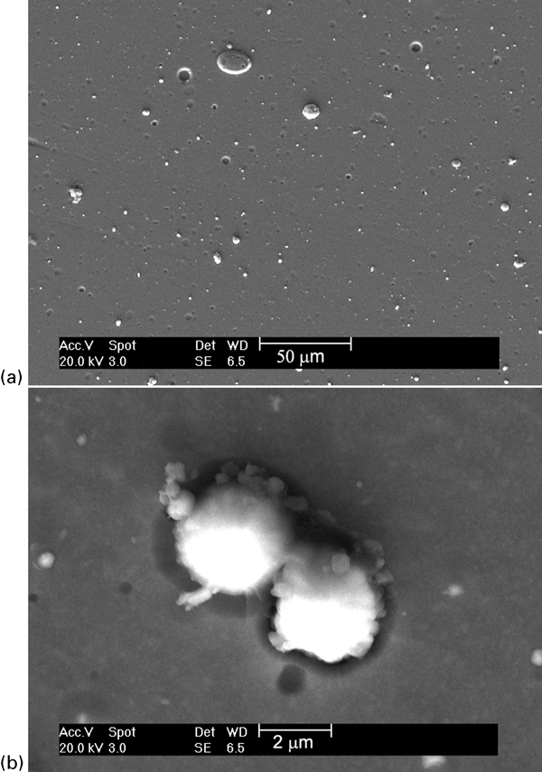
Images (SEM) showing surface of as deposited TiN/SS system after EIS testing
Electrochemical impedance spectroscopy fitting results for as deposited TiN/SS and PMMA treated samples
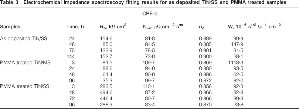
The EIS spectra of PMMA treated TiN/MS and TiN/SS systems are presented in Figs. 9 and 10 respectively. For the TiN/MS system, PMMA treatment significantly increased the corrosion resistance as the impedance modulus at 10 mHz maintained a much higher value than the as deposited TiN/MS over a period of six days. The PMMA treated TiN/SS system quickly reached a steady state and maintained the highest polarisation resistance R p throughout the entire exposure period (Table 3). Furthermore, the R p value for PMMA treated TiN/SS was significantly higher than that of the as deposited counterpart. The coating surfaces of both PMMA treated specimens after immersion testing, when observed under SEM, showed similar features as those before the testing with no sign of corrosion products. Polymethyl methacrylate was found to remain in the adjacent areas surrounding nodules and nodule detached crater surfaces. Therefore, the significant enhancement in the corrosion resistance of the coated systems indicates that the PMMA treatment can effectively alleviate detrimental effects of the coating defects on corrosion performance.
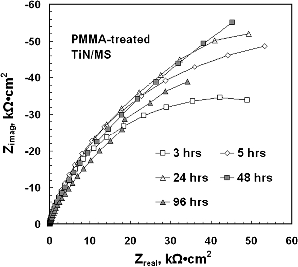
Nyquist plots of PMMA treated TiN/MS system after various immersion time periods
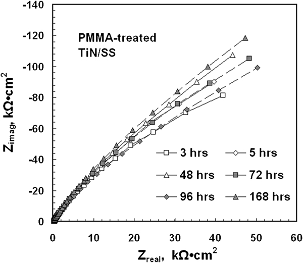
Nyquist plots of PMMA treated TiN/SS system after various immersion time periods
Conclusions
Coating defects such as nodules and craters left by detached nodules were observed on as deposited TiN coating surfaces. Potentiodynamic polarisation measurements demonstrated that as deposited samples had a higher corrosion potential and lower anodic current density than the substrates. Post-deposition PMMA treatment further increased the corrosion potential and lowered the anodic current density. Impedance measurements over a long exposure time in the NaCl solution revealed that the defects in the TiN coatings provided easy access for the corrosive media to reach the substrates, resulting in the degradation of the coating performance against corrosion, especially for the system with less corrosion resistant MS substrate. Electrochemical impedance spectroscopy measurements and SEM analysis found that post-deposition PMMA treatment successfully prevented the corrosive media from reaching the substrate by sealing pores, imparting higher corrosion resistance to PMMA treated specimens than their as deposited counterparts.
Footnotes
Acknowledgements
The authors would like to thank Ontario Centres of Excellence (OCE) for providing financial support for this research. The help from Mr McKellar of the National Research Council Canada in coating deposition is highly appreciated.