
Abstract
The 2012 Eurocorr meeting was held at the Sheraton Maslak hotel in Istanbul from 9-13th September 2012. The focus of the meeting was ‘Safer world through better corrosion control’. The meeting attracted over 650 delegates and over 360 oral presentations and 125 posters were presented during the 27 sessions and workshops. Parts 1-4 will review the technical sessions over four issues with technical sessions on marine corrosion, marine renewable energy, corrosion of steel in concrete, corrosion in the oil and gas industry, corrosion in the refinery industry and CO2 Corrosion in CCS applications covered in this report.
Marine Corrosion
The main marine corrosion session ran through on Thursday morning until the conference finished at lunchtime. The chair of this working party is Ulf H. Kiväskk from A.B. Sandvik Materials Technology, Sandwiken, Sweden and he was assisted by M. Grolleau and C. Powell. The first talk was ‘Corrosion performance of coatings for cruise ship external superstructures’ given by X. Zhang, from TNO, Den Helder, The Netherlands. Carbon steel sheets were grit blasted to Sa2½ and coated with a shop primer by automatic devices. Three types of coatings were then applied: Coat-A was epoxy plus polyurethane, Coat-B epoxy plus acrylic polysiloxane, and Coat-C epoxy plus acrylic polyurethane. Electrochemical impedance spectroscopy measurements were performed during exposure to sea water with continuous immersion and with wet/dry (under UV) cyclic method. The galvanic effect on the coatings (e.g. anodic and cathodic disbonding) were studied by applying potentials (−0·45 and −1·1 v Ag/AgCl) to the coated samples with an artificial holiday in a diameter of 6 mm and measuring the currents as a function of time. The adhesion of the coatings was measured using pull-off tests. Comparing the three systems, it was concluded that Coat-B showed the best corrosion protection. This system also had the lowest sensitivity to UV degradation during wet/dry cyclic exposure. The adhesion properties of the Coat-B and Coat-C coating systems were satisfactory. Coat-A gave low pull-off strength values. This was attributed to the relative low cohesive strength of the intermediate layer. The second talk was ‘Monitoring of seawater biofilms on stainless steel for corrosion risk assessment’ from D. Thierry working at the French Corrosion Institute, Brest, France. Although ennoblement of OCP on stainless steel due to biofilm has been extensively reported, its effect on localised corrosion and in particular to crevice corrosion is only scarcely documented. The objective here was to develop an autonomous sensor able to characterize seawater biofilms on stainless steel surfaces through their electrochemical effects. An adapted autonomous CPC sensor was used to characterise the potential ennoblement in temperate seawater (Brest, France). Galvanic current density measurements allowed the quantification of the cathodic efficiency of the stainless steel surface, as a function of the nature of the biofilm (effect of season, temperature, etc.). This was found to bring more complete information than just making potential measurements. The cathodic efficiency of the biofilm was found to be temperature dependant. The last paper from this session was delivered by Metin Taylan from ITU, Istanbul, Turkey who described ‘The impact of corrosion in shipbuilding industry’. It was pointed out that the cost of corrosion for the U.S. vessels, excluding Navy vessels, was about $2·7 million according to a study in 2001. To try to reduce this expense, particularly in relation to the Turkish ships and ship owners, the talk pointed out the importance of correct material selection and good design throughout the construction period. It was also emphasised that the main corrosion protection scheme will only come into play when the ship is near completion. At that stage painting and coating systems have to be applied according to the procedures set out in the rules and specifications along with a compatible cathodic protection system. The life of the paint system depends on the quality of surface preparation as much as the paint itself. Also stressed was that corrosion prevention does not end when the ship starts its operation, on the contrary, it stretches out to the lifetime with inspection at periodic intervals. Some examples of good practice were given.
Marine Renewal Energy workshop
Internal side of transition piece surface within a wind turbine leg. Photo Courtesy of Lisbeth Hilbert, Force Technology)
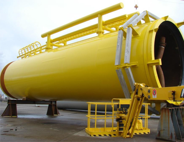
Transition piece coated externally and with anodes in place for CP : Photo courtesy of Lisbeth Hilbert
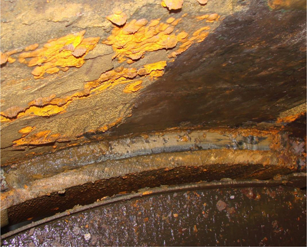
The Marine Renewable Energy Workshop (G on the ROM) ran on Wednesday immediately after lunch. It was chaired by Lisbeth Hilbert from FORCE Technology, Brøndby, Denmark with help from P. Demt. There were four full papers on the ROM. Two of these have been chosen for comment here. The first paper discussed problems inside the towers. This was ‘Corrosion control inside offshore wind farm monopile foundations’ given by Lisbeth herself. She stressed that good design, coating and cathodic protection are all possible modes for enhanced corrosion protection inside a monopile foundation. Control requires feedback, and all future farms should have regular inspections and/or a continuous remote monitoring built in. In cases where a particular design has led to severe corrosion attacks (see picture), one of three proposed actions may be taken: repair and wait, clean and coat, or install cathodic protection and monitor. An intelligent corrosion monitoring programme thorough remote surveillance of the wind farm would be the optimum but if this is not possible then simple coupons may provide the necessary documentation. As offshore wind farms become larger eg. in cases with more than 100 foundations, the benefits of remote monitoring may prove substantial, reducing repair costs significantly. This was followed by ‘Protective coatings for offshore wind farms’ delivered by Ole Øystein Knudsen, SINTEF, Trondheim, Norway. The NORSOK M-501 coating specification standard may be applicable to the offshore wind industry, but needs to be adapted to better serve the needs in offshore wind. The paint system on top of the thermal spray zinc could be simplified without increasing the need for maintenance. Hence various coating systems were investigated in both lab and field tests, and evaluated with respect to performance and the potential for cost savings. Test panels of regular construction steel (C-steel, S 235) were blast cleaned and coated with various coating products based on epoxy, polysiloxane, and polyester. The thermal spray zinc (TSZ) coating was an alloy consisting of 85% zinc and 15% aluminum. Five coated panels (100 x 400 mm) of each coating system were mounted on frames in the tidal zone in the harbour on the isle of Helgoland in the German North Sea. The coating on the samples was scribed down to the steel with a width of 2 mm and the samples were exposed from beginning of June 2010 and examined at least every 6 months. In the lab the ageing resistance of the coatings was tested according to ISO 20340. Results showed that several coating systems performed very well, indicating that they may not need maintenance during the lifetime of an offshore wind turbine. This reporter will just comment that he realized some time ago that this would become an important area. The aim must be to keep the towers throughout their lifetime in the same (or close to the same!) excellent condition as they are in at the start (see picture). Back in 2006 he presented a paper himself at a EuroCorr (work was done by a student called Stephen Donoghue) on the effect of abrasion and uv light on coatings for such towers and the ability to pick any deterioration up with electrochemical techniques like EIS or DC resistance. The conclusion was that yes it was! These techniques could hence be used as part of a planned maintenance system either using built in probes or on existing systems, some sort of ‘crawler’.
Corrosion of Steel in Concrete
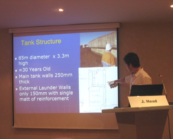
J. Head-presenter-concrete session
There were 12 full papers on this topic which took place on the Tuesday and Wednesday. The Chairman was Michael Raupach, RWTH, Aachen University, Germany. Four papers have been chosen for comment here. ‘Chemical transformation of zinc passivating products after carbonation process’ was presented by T. Bellezze, Università Politecnica delle Marche, Ancona, Italy. Previous work on galvanized steel sheets embedded in concrete submitted to carbonation showed a layer of calcium hydroxyzincate Ca[Zn(OH)3]2 .2H2O (CHZ).
Conclusions were firstly that the CHZ layer, determines the passivity state of zinc when Ca(OH)2 solution is exposed to the atmosphere, but is destroyed by the carbonation process; secondly, X-ray diffractometry and Raman spectroscopy demonstrate that the reaction products of CHZ with CO2 are hydrozincite Zn5(CO3)2(OH)6 and calcite (CaCO3); thirdly, SEM observations confirm the deep transformation in the passivating layer caused by carbonation. Finally, corrosion potential and corrosion rate measurements indicate that zinc maintains its passivity state also after carbonation, in agreement with the previous research and literature reviews.
D. A. Koleva, Delft University of Technology, Netherlands spoke on, ‘Steel corrosion resistance in model solutions and reinforced mortar containing wastes’. A comparative investigation of the corrosion behaviour of low carbon steel in model alkaline solutions and reinforcing steel in mortar, using Ordinary Portland cement (OPC), Blast furnace slag cement (BFS) and Red Mud (RM) in chloride containing environment, was made. The variables are: the steel corrosion parameters in both aqueous (model solutions) and solid (mortar) environment and the alterations in the bulk cement-based matrix (porosity, pore size distribution) for the reinforced mortar cases. This is a comparative study of control (non-corroding) specimens from each group and corroding (conditioned in 5% NaCl).
The adhered red mud particles act as adsorption sites for Ca2+, resulting in a product layer (adhered CaO/Ca(OH)2) with higher corrosion resistance. Further investigations involve optimising mixing proportions since the presence of RM is necessary in order to obtain improved corrosion resistance.
M.G. Sohail, Universite de Toulouse, France presented, ‘Numerical study of an accelerated corrosion test in concrete, effects of corrosion parameters on macrocell corrosion system’.
Corrosion process can be divided into two phases: initiation phase and propagation phase. The corrosion process accelerates in the initiation phase, which in this work, is accelerated by an artificial environment in which concrete is kept in a carbonation chamber set at 50% CO2 and 65% RH.
Firstly, it was concluded that concrete resistivity takes account of temperature, humidity and porosity. With higher values of resistivity, ohmic drop is quite significant and macrocell corrosion current is very small and vice versa. The face of the active steel which faces the passive steel bar is more polarized than the opposite side. Secondly, after depassivation of steel bar, the desired level of corrosion in RC can be achieved by controlling the cathode surface area. Thirdly, research should be carried out to build a dynamic model in transitory state of corrosion, taking account of capacitance of the concrete-steel interface.
‘The effect of molybdenum on the corrosion performance of stainless steel in chloride-contaminated and carbonated concrete’ was delivered by Z. Panossian, CINTEQ, IPT, São Paulo, Brazil. Samples of ferritic, austenitic and duplex stainless steels were produced in laboratory with controlled levels of Mo and immersed in simulated carbonated and noncarbonated concrete pore solutions, both with the addition of 3·5% sodium chloride. Samples were also embedded in concrete that was later carbonated and exposed to saline solution. The 3% Mo addition increased the crevice corrosion resistance for all laboratory SS families even for the austenitic ones, which presented anomalous results in the synthetic carbonated pore concrete solution (pH 10). The 23Cr4·6Ni3Mo (En 1·4462) duplex stainless steel presented the highest corrosion resistance under the studied aggressive concrete conditions. Methods should be improved in order to avoid crevice corrosion during the electrochemical experiments.
Corrosion in Oil & Gas Production
There were 53 papers on this topic of which 19 were full papers. Five papers are reported here. Sessions took place on the Monday and Tuesday, the Chairman being Michel Bonis of Total SA, France (assisted by J. Kittell and M. Achour). A paper of fundamental importance was, ‘Hydrogen evolution in aqueous solutions containing dissolved H2S: evidence of direct electro-active contribution of H2S’ by J. Kittel, IFP Energies Nouvelles, Solaize, France. The hydrogen evolution reaction in an oxygen free solution with dissolved H2S is radically different from that with dissolved CO2, even though both dissolved gases are weak acids of comparable solubilities and pKa values. With dissolved CO2, proton reduction is the main cathodic reaction.
However, the results presented in this paper demonstrated that the buffer effect was insufficient to explain the cathodic polarization curves measured in solutions with dissolved H2S. At low cathodic overpotentials, it appeared that the system was not strictly under activation control. Understanding the detailed mechanism of H2S reduction requires further work.
K. Kobayashi, Sumitomo Metal Industries, Ltd., Japan, then presented a paper on the ‘Effect of buffer solution type on KISSC values of low alloy steel’. The sulphide stress cracking (SSC) susceptibility of carbon and low alloy steels is strongly affected by solution pH and H2S partial pressure. The DCB (double cantilever beam) test was used to evaluate the SSC susceptibility. 110 ksi grade low alloy steel OCTG for sour service was used.
First, the effects of total acetic acid and balance gas (N2 and CO2) in the acetic acid buffered solutions on SSC behaviour were evaluated. Subsequently, the SSC behaviour in the CO2-HCO3 buffered solution was compared with the above solutions; then the effects of CO2 partial pressure on SSC behaviours were investigated. KISSC values decreased as the total acetic acid was increased. The presence of the corrosion product with high protectiveness produced in the high pCO2/pH2S condition suggests that the conventional test conditions with acetic acid are more severe than the actual field conditions.
‘Experimental and numerical study of diffusion and trapping of hydrogen in steel pipelines’ was delivered by E. Fallahmohammadi, Politecnico di Milano, Milano, Italy. Experimental permeation transients and general McNabb and Foster model of diffusion plus-trapping, were compared in order to find the trapping characteristics. Experiments were carried out on micro-alloyed C-Mn steel, API 5L X65 grade, and a 2·25 Cr- 1Mo steel, ASME SA-182 F22.
Firstly, it was concluded that in the presence of trapping, apparent diffusion coefficient of H in steel decreases continuously; secondly, partial transient seems a more reliable technique to study the lattice diffusivity of hydrogen in the Devanathan Stachurski method; thirdly, the activation energy of diffusion derived from temperature dependence of effective diffusion coefficient of hydrogen atoms in two steels has been estimated as 19·6 and 25·5 kJ mol−1 for F22 and X65 respectively. Finally, analysis of the hydrogen desorption for steel samples enables both the lattice diffusivity and the concentration of the diffusible hydrogen to be evaluated.
‘The use of alloy 31 and alloy 59 as carcass materials for unbounded flexible pipelines, for highly sour applications’ was the subject of the paper given by L. Ke, Technip, Le Trait, France. Alloy 31 (UNS N08031) and alloy 59 (UNS N06059) were selected by Technip for a carcass material. The test consists of a 30-day immersion of carcass specimens in an deoxygenated aqueous solution, saturated with acid gases, at the required temperature. Test parameters i.e.: H2S and CO2 partial pressures; pH; Temperature and Cl− concentration, were selected to simulate field conditions conservatively.
These tests show that carcasses in alloy 31 and alloy 59 are corrosion resistant enough to withstand highly sour and aggressive applications. As expected, alloy 59 is more corrosion-resistant than alloy 31.
‘Influence of shot peening on the fatigue life of steel armours in flexible pipes’ was given by M. Rogowska, National Oilwell, Varco, Denmark/Technical University of Denmark. The impact of residual stresses imposed by shot peening on the surface of steel wires in flexible pipes on their fatigue life in a corrosive environment, which is relevant when they are used as risers and jumpers in the oil and gas industry was investigated. The corrosion fatigue behaviour was evaluated by applying the 4 point bending test under a corrosive environment compared to fatigue testing in air.
It was shown that samples shot peened after annealing withstood a higher number of cycles compared to non-peened samples. Samples shot peened before annealing lose the effect of shot peening during the subsequent annealing process. XRD measurements confirmed that the long fatigue life of shot peened samples is related to their high compressive residual stresses.
Fatigue and XRD results showed that the production simulation decreases compressive residual stresses and fatigue life of shot peened samples. However, shot peening could be implemented in shorter parts of the pipes or on the armour wires in the end fitting.
Corrosion in the Refinery Industry
There were 15 lectures (10 full papers) on this topic, the Chairman for which was François Ropital, IFP Energies Nouvelles, Solaize, France. Three papers have been chosen for comment here. ‘Guided wave testing for the detection of corrosion under insulation (CUI) in pipes’ was an interesting submission by A. Demma, Guided Ultrasonics Limited, Brentford, UK. A GWT system comprises three components: transducer ring, instrument, and a laptop computer running the software. Results are displayed in two formats: A-scan and C-scan. The A-scan provides data in which the vertical axis is amplitude and the horizontal axis, is the distance from the transducer ring position. A C-scan map is where the vertical axis is the angular position around the pipe circumference and the horizontal axis is distance.
Guided Wave Testing (GWT) enables inspection of a relatively long length of pipe from a single test location. This is therefore an approach that can be used in which the insulation removal is kept to a minimum while up to 100% of the axial section under investigation can be covered.
‘Evaluation of an electrochemical method to determine critical crevice corrosion temperatures’ was discussed by R. Pettersson, Outokumpu Stainless AB, Avesta, Sweden. In this investigation, further development has been made of a new electrochemical method to evaluate the critical crevice corrosion temperature (CCT) in 1M NaCl. The crevice corrosion temperature is defined as the temperature of the specimen at which the current density exceeds a specified value. A recommended value for pitting corrosion is 100μA/cm2, referring to area exposed in the measurement i.e. 1 cm2. Using a slow temperature ramp of 0·1°C/min gives lower CCT-values but for ranking purpose a faster temperature ramp of 1°C/min can be used. It was also concluded that it is most appropriate to evaluate the CCT at a low current of 10 μA since crevice corrosion attack clearly can be seen at this level and there is less effect of the experimental set-up. This has then been applied to two stainless steels, the super-duplex 2507 and the high-alloyed austenite 904L to evaluate different factors that can influence the measured CCT.
M. Golozar, University of British Columbia, Vancouver, Canada outlined, ‘Corrosion behaviour of Alloy 617 in PbCl2 – KCl molten salt system’. Electrochemical experiments were performed under 3-electrode and 2-electrode systems using potentiodynamic, linear polarization, and electrochemical impedance spectroscopy methods in order to examine the in situ electrochemical behaviour of the alloy at 650°C and 800°C. In addition, thermal analyses were used to characterize the phase transformation of the salt at different temperatures ramped between 25°C and 800°C. Scanning electron microscopy was used to examine the cross section of the alloy at different temperatures after exposure to the molten salt.
It was concluded that the electrochemical method for determining critical crevice corrosion temperatures seems robust and gives sufficiently small standard deviations. This makes it a useful tool for both assessing the environmental conditions in which there is a risk for crevice corrosion and for ranking different alloys.
Task Force: CO2 Corrosion in CCS Applications
There were 9 lectures on this topic, three of which are reported below. The Chairman of the session, which took place on the Monday, was Ralph Baessler of BAM, Berlin, Germany. P. Pearson, CSIRO Energy Technology, Clayton, Australia lectured on, ‘Corrosion in amine post combustion capture plants’. The corrosion observed on carbon steel (CS1018) corrosion coupons installed in an operating carbon dioxide Post Combustion Capture (PCC) pilot plant using monoethanolamine (MEA) as an absorber was monitored. Laboratory-measured corrosion rates under deoxygenated conditions were an order of magnitude higher than corrosion coupon data from the pilot plant. The difference in measured corrosion rates was most likely due to intermittent use of the pilot plant, and the ‘instantaneous’ corrosion rate measured in laboratory versus a slowing rate of corrosion on the coupons due to scale build up. If the laboratory measured corrosion rates under deoxygenated conditions are used to design a PCC plant, confidence can be placed in actual corrosion rates in the plant being lower. The laboratory study also revealed two possible corrosion protection mechanisms: increase the oxygen content or raise the system potential to the passive region in an deoxygenated system.
In a similar vein, ‘Corrosion in post-combustion CO2 capture plants – comparisons between MEA 30% and new processes’ was a lecture given by J. Kittel, IFP Energies Nouvelles, Solaize, France, Monoethanolamine presently represents the benchmark solvent for this application. It was shown that this solvent was quite corrosive to carbon steel, requiring stainless steel as a construction material. Two different processes were presented. The first one comprises optimisation of the usual MEA process. It was shown that the risks of oxidative degradation increase considerably, but can be significantly reduced by efficient oxidation inhibitors which could interact with the passive layer of usual austenitic stainless steel grades, allowing fast uniform corrosion. The second process uses a different type of amine, separating two liquid phases at high temperature when loaded with CO2. Finally, corrosion by this new solvent appeared to be much less than with conventional MEA. Therefore, less costly construction materials should be employed, the use of expensive proprietary corrosion inhibitors being avoided.
Corrosion of steels in CO2 transport and storage environments’ was the paper given by X. Zhang, TNO, Den Helder, Netherlands. The corrosion behaviour of steel S355 and stainless steel 316L in CO2 flue gas solutions and casing steel N80 in CO2 saturated brine were investigated using electrochemical techniques in an autoclave. The corrosion rate of the N80 casing steel in brine plus supercritical CO2 measured by polarization measurements is as high as 6 mm/y at the beginning and it decreases to 0·3 mm/y after one week. After one week the corrosion rate at 100 bar is lower than at 60 bar. The mass loss test shows an average corrosion rate of about 0·06 mm/y in 32 days. A scale formed on the metal surface is dolomite CaMg0·77Fe0·23(CO3)2 determined by XRD analysis, which hinders the casing corrosion process. Stainless steel 316L has much lower corrosion rate than the steel S355 in the flue gas solution. The average corrosion rate is lower than 1 μm/y. The corrosion rate for S355 in the CO2 plus de-ionized water at 100 bar and 60°C decreases with time from 0·35 to 0·02 mm/y after 6 days.