
Abstract
Carbon steel is one of the candidate overpack materials for geological disposal of high-level radioactive waste in Japan. Corrosion of carbon steel is classified into two types: general corrosion and localised corrosion. In this study, propagation of general and localised corrosion (pitting corrosion and crevice corrosion) were investigated by immersion tests of carbon steel under the aerobic conditions. The results of the immersion tests showed that the corrosion growth rate was strongly dependent on the environmental conditions and type of steel. However, the upper limit of the pitting factor, the ratio between the maximum corrosion depth and the average corrosion depth, was determined approximately using only average corrosion depth. Based on the experimental and literature data, an empirical model that predicts the maximum corrosion depth of an overpack from average corrosion depth was developed by applying the extreme value statistical analysis using the Gumbel distribution function.
Introduction
The multibarrier disposal system for high level radioactive waste consists of vitrified waste, overpack, buffer material and the surrounding rockmass. In this system, overpack is required to remain intact for at least 1000 years, preventing groundwater coming into contact with vitrified waste.1 The main factor limiting this function is corrosion due to contact with groundwater infiltrating through the buffer material, a mixture of bentonite and sand. Carbon steel is a candidate material for overpacks in Japan; it is a corrosion allowance metal by design. Corrosion of carbon steel occurs in two forms: general corrosion and localised corrosion. The latter, such as pitting and crevice corrosion, is attributed to local breakdown of the passive film in the presence of aggressive ions such as chloride ions. However, in a high level radioactive waste repository environment, general corrosion will be the most probable corrosion type, because bentonite prevents formation of a stable passive film on the surface of carbon steel.1 However, there are some factors that can induce the passivation and consequent potential for localised corrosion on carbon steel overpack material. One typical cause of passivation is the rise of pH in groundwater due to contact with cementitious material in the concrete structures needed for support of the rockmass around excavations. Given such a situation, both general and localised corrosion should be taken into consideration in assessment of the lifetime of the carbon steel overpack. In this study, propagation of general and localised corrosion were investigated by immersion tests of carbon steel under the aerobic conditions. Some of the immersion tests were performed using welded coupons cut from samples of a full scale protype of an overpack lid welded by different methods: tungsten inert gas (TIG), metal inert gas (MAG) and electron beam welding (EBW).2 – 4 Extreme value statistical analysis using the Gumbel distribution function was applied to the maximum corrosion depth data. Based on the results of the analysis, an empirical model for the assessment of maximum corrosion depth of carbon steel overpack was derived.
Experimental
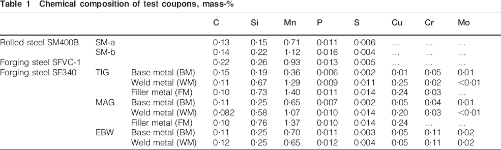
The test coupons were made from rolled steel (JIS G3106 SM400B) and forging steel (JIS G3202 SFVC1 and JIS G3201 SF340). The chemical compositions of the test coupons are shown in Table 1. Immersion tests for SF340 were performed using welded coupons cut from a full scale model of an overpack lid welded by different methods: TIG, MAG and EBW methods.2 – 4 In TIG and MAG welding, filler wires are required for the welding. Therefore, the chemical composition of the welded metal is different from that of the base metal. For general corrosion testing, the coupons were cut into a rectangular shaped 60×120×5 mm, in conformity with Ishikawa et al.5 For localised corrosion testing, disc shaped coupons with a diameter of 80 mm and a thickness of 2 mm were used and polysulphone crevice formers with a diameter of 20 mm and a thickness of 5 mm were attached to the centre on each side of the specimen. The exposed surface area of the test coupons was 131·0 cm2 for general corrosion and 104·6 cm2 for localised corrosion. The surface of the coupons was polished to an #800 emery paper finished and rinsed with acetone.
Chemical composition of test coupons, mass-%
In this study, general corrosion behaviour was examined in synthetic seawater (SSW, ASTM D1141) and synthetic freshwater (SFW, 2·5 mM NaCl–2·5 mM NaHCO3) with reference to Ishikawa et al.5 In order to simulate the use of buffer material, several immersion tests were also performed in the presence of bentonite, the main component of buffer material. The proportion of bentonite to test solution was 1 g buffer per millilitre of solution.
Localised corrosion behaviour was examined in aqueous alkaline solutions containing carbonate that serves as a passivator for carbon steel6 and alkaline saline water set up by mixing with powdered concrete. The concrete was made from ordinary portland cement (OPC) and from low alkaline cement of high flyash and silicafume cement7 (HFSC). The composition and pH of the test solutions for localised corrosion are as follows:
highly corrosive carbonate (HCC): [NaCl] = 0·56M, [Na2SO4] = 0·052M, [NaHCO3] = 0·01M, pH = 8·4
less corrosive carbonate (LCC): [NaCl] = 0·027M, [NaHCO3+Na2CO3] = 0·1M, pH = 10
alkaline carbonate (AC): [NaCl] = 0·56M, [Na2CO3] = 0·1M, pH = 11, 12, 13·4 (adjusted by NaOH)
saline water with OPC (SWOP): [NaCl] = 0·56M, pH = 13
saline water with HFSC (SWHF): [NaCl] = 0·56M, pH = 11.
For SWOP and SWHF solutions, the two types of concrete blocks were crushed to a fine powder with a mesh size of <1 mm and then mixed with 0·56M NaCl solution for 10 days. The final pH values of water in contact with powdered concrete were ∼13 (SWOP) and 11 (SWHF). In addition to generic general and localised corrosion tests, immersion tests under the actual groundwater conditions at Horonobe Underground Research Laboratory were performed as an example of typical marine groundwater. The test solutions simulating the Horonobe groundwater conditions are as follows:
natural Hronobe groundwater (NHW): [Cl] = 0·18M, [C(total)] = 0·026M, pH = 6·8 (measured value8)
synthetic Horonobe groundwater (SHW): CaCO3 (saturated)+NaCl (0·28M)+CO2 (g) (0·05 MPa)
synthetic Horonobe groundwater with OPC (SHW+OP): pH = 13
synthetic Horonobe groundwater with HFSC (SHW+HF): pH = 11.
The number of coupons to apply extreme value statistical analysis for each condition was N = 15 for the base metal and N = 3 for the welded coupons. The temperature was fixed at 353 K to simulate the representative condition at the overpack surface during the initial oxidising period in a repository at which localised corrosion can occur.1 The experimental procedures were as follows. The test coupons were immersed in the test solutions in glass test cells with a capacity of ∼3 L. During each test period, air was bubbled through the test solutions to maintain oxidising conditions. After the immersion period, all the coupons were removed from the test solution and the corrosion products were removed in a 10% diammonium hydrogen citrate solution and with a cathodic current of ∼1 mA cm−2. After removal of the corrosion products, the mass loss of the coupons was measured for calculation of the average corrosion depth. Finally, the corrosion depth on the entire surface of each specimen was measured using a three-dimensional laser profilometer device, and the maximum corrosion depth determined as the distance from the non-corroded surface level.
Extreme value statistical analysis
The extreme value statistical analysis technique was applied to the measured maximum corrosion depths of the base metal coupons to estimate the maximum corrosion depth for a full-scale overpack. Assuming a Gumbel distribution, the cumulative probability F(x) is given by


Results and discussion
Appearance of coupon surfaces
Examples representative for the appearance of the coupon surface after immersion are shown in Fig. 1. In SSW, as an example of general corrosion, the entire surface of the coupon was corroded and no obvious localisation was observed on base metal coupons. However, preferential corrosion was observed on the welded TIG coupons. Preferential corrosion occurred along weld layers or along entire metal welds. Similar characteristics were observed on the welded MAG coupons. On the other hand, for EBW coupons, no preferential corrosion of the welded metal was observed and the corrosion depth of the weld zone was smaller than or equal to the corrosion of the base metal. One of the causes of preferential corrosion on TIG and MAG coupons is considered to be chemical compositional changes in the welded metal due to the use of filler wire. The concentrations of Si, Mn and S in the filler metal used for TIG and MAG welds are higher than those in the base metal, as shown in Table 1. Silicon, manganese and sulphur are elements that have known detrimental influence on the corrosion resistance of carbon steel welds. 9 9,10 Another possible cause is microstructural changes in the weld zone due to thermal effects induced by welding. The welds in TIG and MAG welding are multilayered structures consisting of as-welded and reheated areas. The as-welded areas mainly consist of acicular ferrite and grain boundary ferrite.2 – 4 Huang et al.11 pointed out that the ratio of acicular ferrite and grain boundary ferrite affects the corrosion rate of welded carbon steel. In HCC solutions as an example of localised corrosion, not only crevice corrosion around the crevice former was observed, but also pitting corrosion away from the crevice former was observed and corrosion on the surface was not uniform. In particular, relatively deep corrosion was observed on TIG and MAG welded metal coupons; some of the corrosion fully penetrated the coupons. In Horonobe groundwater, entire coupon surfaces were corroded in NHW and SHW indicating general corrosion propagation. On the other hand, in SHW+OP and SHW+HF, the coupon surfaces were only partly corroded indicating localised corrosion propagated in groundwater equilibrated with cement.
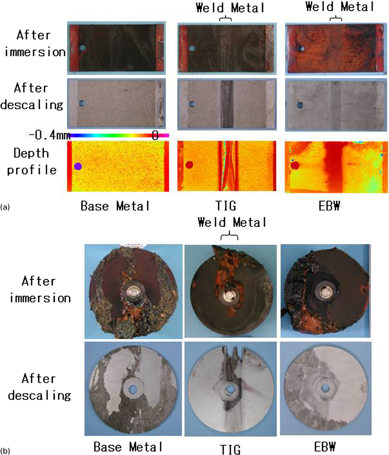
Example coupon surfaces after 90 day immersion in a SSW and b HCC
Maximum corrosion depth
Representative results of extreme value statistical analysis, Gumbel distribution plots, obtained in synthetic seawater are shown in Fig. 2. The parameters α and λ were obtained and the maximum corrosion depth of overpack was estimated as a mode X max and P max as a point at a = 0·99. In this analysis, the overpack surface area S was assumed to be 55 129 cm2, based on the current reference overpack1 design. Therefore, T was calculated to be 421 for general corrosion and 527 for localised corrosion. The P max (mm) was approximated by the following equation

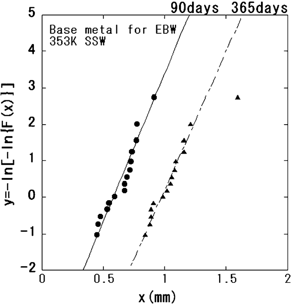
Results of Gumbel distribution analysis for SF340 coupons in SSW
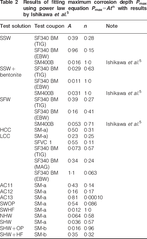
Results of fitting maximum corrosion depth P max using power law equation P max = At n with results by Ishikawa et al.5
Pitting factor
The pitting factor is defined as the ratio between maximum corrosion depth and the average corrosion depth. All the pitting factors observed in this study and found in the literature are plotted by classifying general corrosion, localised corrosion and natural environment corrosion12 – 14 as a function of average corrosion depth, as shown in Fig. 3. The results in Horonobe groundwater without cement (NHW and SHW) are included in the general corrosion group and those of SHW+OP and SHW+HF are in the localised corrosion group. According to Fig. 3a, there is little correlation between the average corrosion depth and the pitting factors for general corrosion, but the upper limit of the pitting factors seems to decrease with increase in average corrosion depth. The pitting factor values for TIG and MAG show a relatively larger distribution due to preferential corrosion of welded metal. However, almost all values are within the upper limit for base metal. Pitting factors of localised corrosion at an average corrosion depth in the order of <10−2 mm were relatively high, more than several tens, but decreased with increase in the average corrosion depth (Fig. 3b). A similar tendency was observed in the data for natural water and soils (Fig. 3c). The integrated data are shown in Fig. 3d. When the average corrosion depth is >10−1 mm, the pitting factor range was similar in general corrosion, localised corrosion and corrosion in natural water and soils.
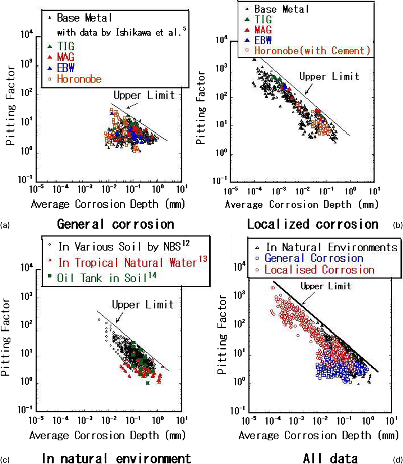
Relationship between average corrosion depth and pitting factor for a general corrosion and b localised corrosion, c in natural water and soils and d integration of a–c
Empirical model to evaluate maximum corrosion depth of overpack during oxidising period
In general, the time to failure due to corrosion of a metallic structure is evaluated by the model on the time dependency of maximum corrosion depth as expressed by equation (5). 12 12,15 Following this general approach, the maximum corrosion depth of a carbon steel overpack was calculated using the parameters A and n listed in Table 2. The time t is the duration of the oxidising period. Although the period should depend on the geological environment and the design of the repository system, it had been calculated to be <100 years.16 Therefore, the period t was assumed to be 100 years (36 500 days). Since P max strongly depends on the parameters A and n, it widely varied in the range from 0·8 to 1132 mm. Brossia and Cragnolino17 pointed out that the time for penetration of 100 mm thick carbon steel could range from <100 years to over several millions of years,13 i.e. a range of ∼5 orders magnitude. Considering that a repository site has not yet been selected in Japan, this approach cannot provide a conclusive assessment of the maximum corrosion depth. Brossia and Cragnolino17 also pointed out another problem, which is that equation (5) does not take account of the cessation of corrosion. In actual environmental conditions around the overpack, the redox conditions will change from oxidising to reducing as oxygen is consumed; consequently, corrosion will be arrested.
By using a different approach, maximum corrosion depth is likely to be estimated from average corrosion depth on its own regardless of environmental conditions as shown in Fig. 3. Because oxygen would be introduced in the buffer and backfilling material, the upper limit of average corrosion depth is relatively easy to estimate accurately from the oxygen budget. By assuming that all the oxygen corrodes the overpack, uncertain environmental conditions such as groundwater chemistry, microbial influence and oxidising period can be included in this assumption. Based on the Gumbel distribution function, the maximum corrosion depth of the overpack can be represented by equation (4) using the parameters α and λ. By describing these parameters as a function of average corrosion depth, P max can also be expressed as a function of the average corrosion depth. The relationships between the average corrosion depth X m and the Gumbel parameters determined in this study are shown in Fig. 4. α was expressed by a form of  , where k 1 and m are constants. Similarly, λ was expressed by the same equation, but it should always be larger than X m, so that the form of
  with the constants of k 2 and m’ applied. In order to simplify the equation, m and m’ were assumed to be equal to 0·5 for general corrosion and 0·25 for localised corrosion. The following equations for upper α (mm) and λ (mm) were obtained as a function of X m (mm)


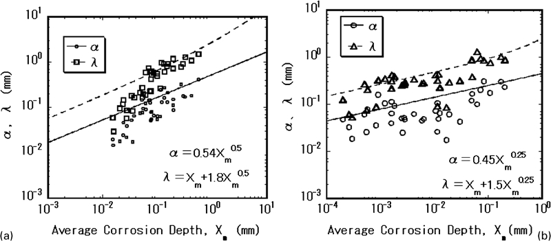
Relationship between average corrosion depth and Gumbel distribution parameters α and λ
general corrosion
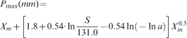
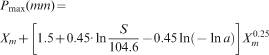
When S is 55 129 cm2 based on present overpack design1 and a is 0·99, equation (8) for general corrosion and equation (9) for localised corrosion can be expressed by


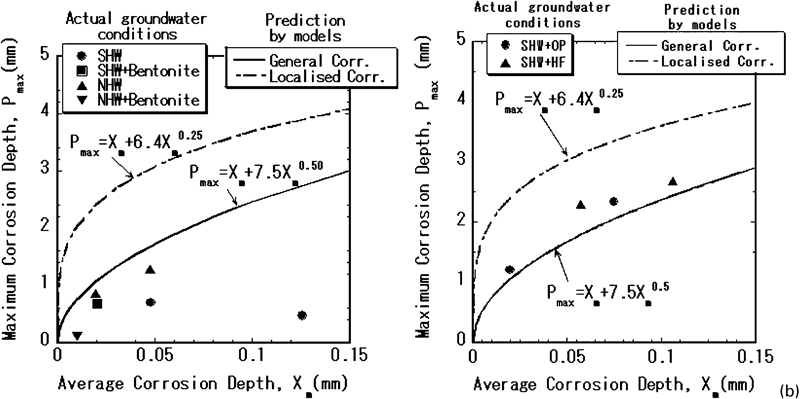
Comparison of model predictions with results under Horonobe groundwater conditions in a NHW and SHW and b SHW+OP and SHW+HF
Conclusions
Although preferential dissolutions were observed in the weld metal of TIG and MAG coupons both in general and localised corrosion environments, the pitting factors were in the range of those of the base metal coupons.
In Horonobe ground water environments, carbon steel coupons underwent general corrosion in the solution without cement. In water in contact with cement, localised corrosion was observed.
The growth rate of general and localised corrosion depended not only on the environmental conditions but also on the type of steel. Therefore, the model of P max = At n gives a large range of values for wide variations of A and n.
According to laboratory test data and literature data in natural water and soils, the upper pitting factor limit can be estimated from the average corrosion depth.
The empirical models as a function of average corrosion depth were suggested based on the Gumbel distribution parameters for general and localised corrosion. Consequently, the applicability of the model to Horonobe groundwater conditions could be verified.
Footnotes
Acknowledgements
This research is part of the Investigations into Engineering Barrier Material Characteristics under a grant from the Japanese Ministry of Economy, Trade and Industry (METI).