
Abstract
The weld joint of the carbon steel overpack is required to isolate the sealed vitrified waste from coming into contact with groundwater for a duration equal to the base metal, which is 1000 years. The authors have proposed a structural integrity evaluation model of the lid closure, which is based on fracture mechanics assessment. Corrosion phenomena at the weld joint and sizing capability of non-destructive examination for weld flaws are key issues in this evaluation model. In this paper, reviewing the most recent test results on the susceptibility of stress corrosion cracking at the weld joint and the estimation of the probability of detection for ultrasonic testing methods, consistency of the evaluation model was discussed.
Keywords
Introduction
The overpack, a container of high level radioactive waste for Japan's geological disposal programme, is required to isolate the sealed vitrified waste from coming into contact with groundwater for 1000 years.1 The same duration and function are required for the weld joint between the body and lid of the overpack. In general, the metal beside a weld is exposed to a rapid thermal cycle of melting and solidification during welding. This cycle induces certain changes including changes to metallurgy, chemical composition, residual stress and surface appearance. Therefore, the long term integrity of the overpack weld joint should be evaluated on the assumption that the welding effects are present.
The authors have initiated studies on a methodology to evaluate the long term integrity of lid closure of carbon steel overpack. These studies include welding tests, non-destructive examination (NDE) tests and corrosion tests using weld specimens. In this series of studies, a structural integrity evaluation model of the lid closure based on the fracture mechanics assessment was proposed.2 – 7
This evaluation method refers to the fitness for service (FFS) assessment of nuclear power plant components, an assessment method specified for the overpack, which takes into consideration the technical limitations caused by emplacement of the overpack in a deep underground geological formation. It is intended to assure the structural integrity of the weld joint for 1000 years without any inspection or repair of the overpack after it is emplaced in a repository.
In this paper, a structural integrity evaluation model is introduced and the results of corrosion tests that are crucial for validating the assumptions underlying this method are presented. The consistency of this evaluation model is also discussed, and the future work that is needed to make the model more reliable is discussed.
The basic specifications of the carbon steel overpack in this paper are based on those included in the ‘Second progress report on research and development for the geological disposal of HLW in Japan’ (the ‘H12 Report’).1
Structural integrity evaluation model for overpack weld joint
Our structural integrity evaluation model was proposed under the condition that weld flaws will necessarily be present at the weld joint. This condition is based on test results for several types of welding methods using carbon steel forgings for general use (SF 340A, JIS G 3201) as welding test specimens for full scale overpack lid structures.
Figure 1a shows the results of gas tungsten arc welding, also known as tungsten inert gas (TIG) welding, as a typical arc welding method applied to a 190 mm thick drop-in lid structure. No significant weld flaws were observed in the macrostructure. On the other hand, in tests using electron beam welding (EBW), a form of high energy beam welding, crack-like flaws induced by welding, cold shuts, appeared at the start end overlapping zones that are produced by the termination of the electron beam, as shown in Fig. 1b. These cold shuts were approximately 1-2 mm in height.
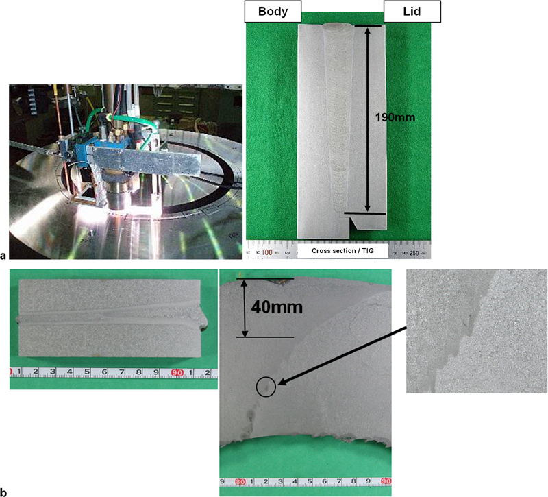
Welding tests for TIG and EBW in full scale lid structure of carbon steel overpack
Fitness for service assessments are quantitative engineering evaluations that demonstrate the structural integrity of an in service component containing a flaw or damage. This assessment covers both the present integrity of the component, given the current state of damage, and the projected remaining life based on a fracture mechanics assessment. The standards prescribed in FFS assessments are currently used in maintenance codes around the world, in both general industry and the nuclear industry. Examples include ASME Boiler and Pressure Vessel Code, Section XI8 and JSME S NAI-20079 for pressure vessels and piping in nuclear power plants, API-57910 for pressure vessels and piping in general use, and BS 791011 for welded structures in general use. One of the most widespread uses of FFS concepts is the justification of life extension for in service components.
The most significant difference between overpack and normal weld structures with respect to structural integrity evaluation is the lack of available inspection and monitoring for overpack, since the overpack must be emplaced in a deep underground repository.
Our proposed structural integrity evaluation model referring to the FFS assessment is shown in Fig. 2.5,7 The objective of this model is to assure that no failures caused by weld flaws are expected to occur during the required containment period of 1000 years, by significantly reducing the positive slope of the crack growth curve (assumption 1) and the negative slope of the material strength degradation curve (assumption 2). Seven prerequisites were stated for this model, primarily for the establishment of these two assumptions. A prerequisite concerning anaerobic corrosion for assumption 2 was newly added in the present study.
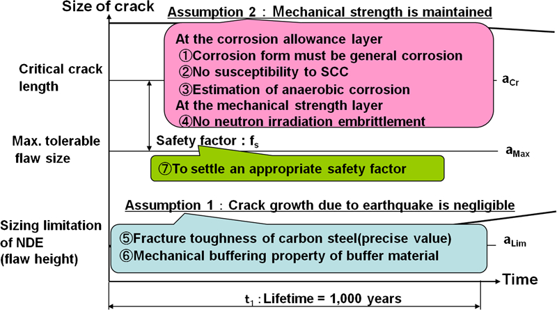
Proposed structural integrity evaluation model for overpack weld joint
As clearly described by the assumptions and prerequisites, the model shows that the structural integrity requirement of 1000 years at the weld joint must be maintained since the related degradation phenomena of the material and the fracture process, which hamper the long term integrity of the weld joint, may be refuted. The authors recognise that there may be a more practical and engineering oriented evaluation method that is deeply connected with the realisation of manufacturing techniques for the overpack final closure.
Corrosion phenomena in structural integration evaluation model
In the proposed evaluation model shown in Fig. 2, three corrosion phenomena were identified by comparing them with the corrosion scenario for the carbon steel base metal:
basically general corrosion
no susceptibility to stress corrosion cracking (SCC)
very low estimate of anaerobic corrosion.
These corrosion phenomena were proposed in JNC's H12 Report as the degradation process at the weld joint.
General corrosion
Taniguchi et al. reported that the form of corrosion in carbon steel under aerobic conditions, including any corrosion in the weld zone, must be general corrosion. This conclusion was reached on the basis of test data concerning pitting factors and the predicted maximum corrosion depth estimated by an extreme value statistical analysis using the Gumbel distribution. It was also pointed out that the maximum corrosion depth of the weld zone did not exceed the depths of the base metal estimated in this study (see LongTermCor2010-08).12
Susceptibility to stress corrosion cracking
With regard to the susceptibility to SCC, it should be noted that certain heat treatments can alter the microstructure and cause changes in the SCC behaviour of low carbon steel in sodium carbonate–sodium bicarbonate solutions (Na2CO3+NaHCO3).13,14
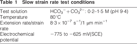
Therefore, to compare the susceptibility to SCC between the base metal and the weld zone, a slow strain rate test was conducted in a carbonate–bicarbonate solution on weld specimens produced by each of the TIG, metal active gas and EBW methods. The test conditions are shown in Table 1. Based on the observations of the fracture surface, the SCC fracture area ratio was calculated as shown in Fig. 3. In the present study, the SCC fracture area ratio is defined as the ratio of observed brittle fracture surface area to the entire fracture surface area. Since the base metal showed the highest value of the SCC fracture area ratio under all welding methods, increased susceptibility to SCC initiation in the carbonate–bicarbonate solutions caused by welding was judged to be refuted.
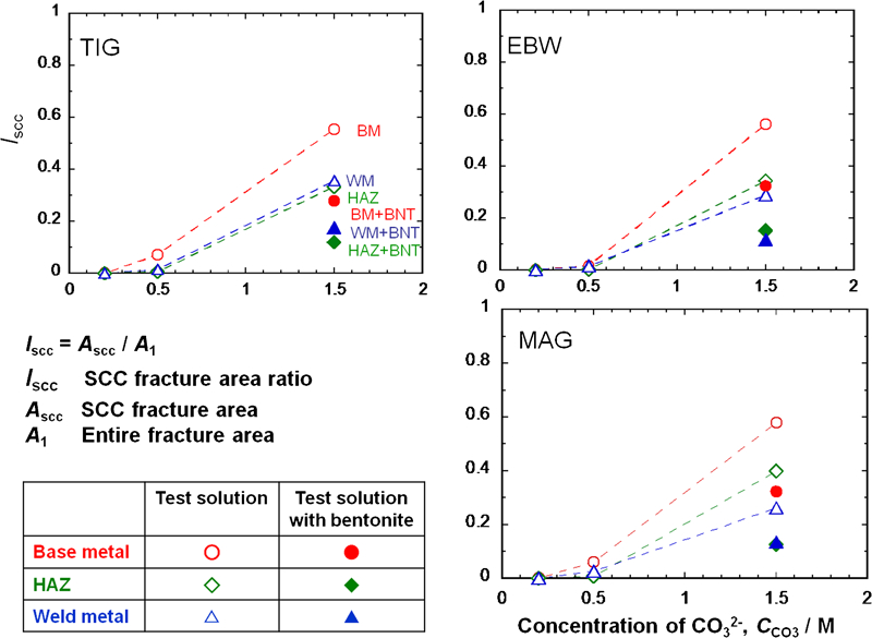
Comparison of SCC fracture area ratio for each welding specimen
Slow strain rate test conditions
Anaerobic corrosion
Kobayashi et al. reported that the average corrosion rate of the weld zone under the anaerobic conditions was <10 μm/year, the proposed corrosion rate for estimating the overpack corrosion allowance presented by the JAEA. They also showed that no significant effects of hydrogen absorption were expected on the basis of measurements of diffusive hydrogen concentrations in the weld zone (see LongTermCor2010-20).15
Detectability of NDE for weld flaws
As described in the section ‘Structural integrity evaluation model for overpack weld joint’, the presence of weld flaws is connected directly to the driving force for the crack growth. In particular, the weld flaw height is recognised as a critical dimensional index in the proposed evaluation model. A crack-like flaw with a height of 1-2 mm was observed at the start end overlapping zones that were welded by EBW in the EBW tests on the full scale overpack lid structure. To evaluate the detection capability of ultrasonic testing (UT) as a NDE for the weld joint, a 190 mm thick carbon steel test specimen was provided and several types of natural defects were intentionally created on the surface and the interior of the test specimen. Given that the detection depth for each UT method could be obtained, a combination of UT scanning techniques was conducted, consisting of creeping wave for the surface and time of flight diffraction (TOFD) and phased array for the area ranging from the subsurface to the bottom. After the UT scanning was complete, destructive examination was conducted to enable visual inspection of the existing defects and their shapes and dimensions. A comparison of the results from NDE (using TOFD) and destructive examination is shown in Fig. 4.
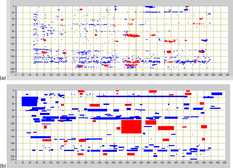
Comparison between a destructive examination and b NDE (TOFD)
The probability of detection (POD) of flaw height for each UT technique is shown in Fig. 5. These POD values were calculated by using the flaw height as the parameter for the approximate equation of the POD curve shown in NUREG/CR-5068.16 Figure 5 shows that a POD of 100% could be obtained for flaw heights up to 2 mm for each UT method.
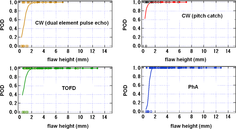
Probability of detection for UT techniques
Consistency of structural integrity evaluation model
In light of the results in above sections ‘Corrosion phenomena in structural integration evaluation model’ and ‘Detectability of NDE for weld flaws’, the structural integrity evaluation model in Fig. 2 was revised as shown in Fig. 6. The critical crack length for a non-ductile fracture calculated from the maximum principal stress generated at the weld joint of the overpack (assumed to be disposed in a granite formation 1000 m below the surface) is shown in this figure as 46 mm. A value of 10 was assumed as the safety factor for this critical crack length by referring to the acceptance criteria for critical flaw size used in the flaw assessment of ferritic vessels in FFS assessments for nuclear power plant components. As a result, the maximum tolerable flaw size was estimated as 4 mm in the proposed evaluation model, as shown in Fig. 6.
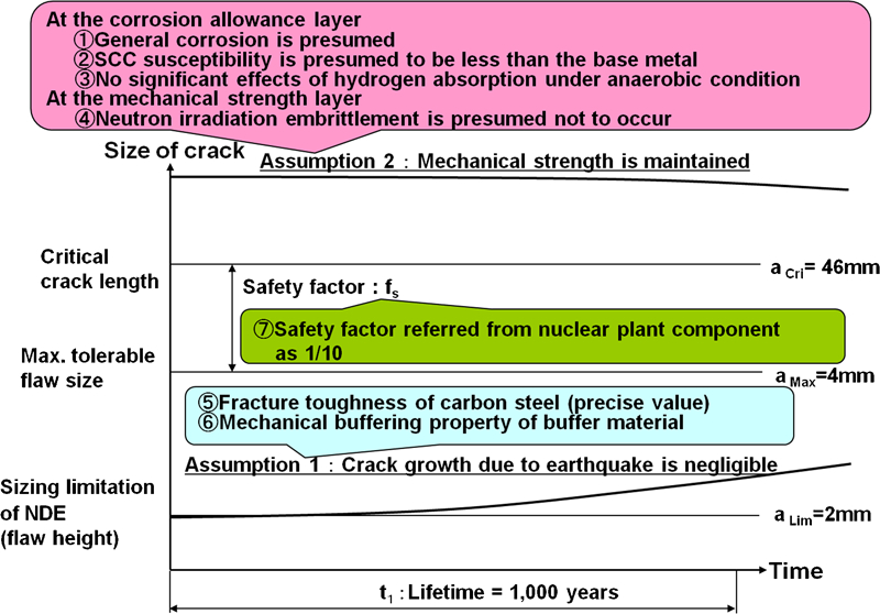
Revised structural integrity evaluation model for overpack weld joint
The test results concerning general corrosion, SCC susceptibility and anaerobic corrosion were consistent with three prerequisites of corrosion issues for assumption 2, as illustrated in Fig. 6. Also, since the radiation dose was 3-4 orders of magnitude smaller than the applicable dose range used in the Japanese embrittlement correlation formula for steel in nuclear reactor pressure vessels,17 it was presumed that neutron irradiation embrittlement at the weld joint due to radiation from vitrified waste inside the overpack does not occur.
For assumption 1, crack growth due to earthquakes was not found. This conclusion is based on a comparison of the estimated values of maximum principal stress at the weld joint due to earthquake loading.5
Therefore, the two assumptions in Fig. 6 are judged to be consistent. The relationships between the evaluation indexes of critical crack length, maximum tolerable flaw size and the limits of NDE size estimation, as shown in Fig. 6, are not contradictory when a safety factor of 10 is applied. These results appear to support the consistency of this structural integrity evaluation model for overpack weld joints.
Discussion
Evaluation method for structural integrity
The authors recognise that the evaluation method in Fig. 6 is essentially different from methods that predict overpack lifetime based solely on corrosion phenomena. In the authors’ model, the overpack is recognised as a type of manmade structure, in the form of a weld structure, which is required to last 1000 years in containment. The long term integrity of the weld joint should be evaluated in light of the potential negative effects from welding. The objective of this model is to assure that failure generated by growth of weld flaws will not occur within a 1000 year period beginning immediately after the closure welding between the body and lid of the overpack is complete, while referring to the fracture mechanics assessment and taking into account mechanical, electrochemical and radiation conditions peculiar to the overpack. To realise this objective, the methodology must incorporate all of the phenomena that may potentially contribute to degradation at the weld joint into a single evaluation model. In this example, the authors chose fracture mechanics assessment as an example methodology.
Evaluation of crack growth
In this paper, the authors have assumed that susceptibility to SCC at the weld joint of a carbon steel overpack is less than the susceptibility at the base metal. It would be good to know whether this is a safe assumption and whether the results of susceptibility comparisons can provide assurance that no SCC will occur during the lifetime of the overpack. Because material degradation may be evaluated on a time axis, crack growth should be observed and evaluated over time to obtain a more reliable assessment of SCC. For corrosion under the anaerobic conditions, an assessment of the cracks is also required.
Although it is recommended that the entire degradation process regarding the integrity of the weld joint should be included in one evaluation model as shown above in the section ‘Evaluation method for structural integrity’, the test method and conditions have a significant effect on the reliability of the evaluation method.
Detectability and sizing of weld flaws
The fundamentally important requirement for using UT methods in NDE of the weld joint is that the testing does not miss weld flaws that may harm the weld joint. In order to make this judgment, the weld flaws must be classified as harmful or harmless, which requires evaluation indexes for their dimensions. Figure 6 shows three such indexes on the vertical axis: critical crack length, maximum tolerable flaw size and NDE size estimation limits. In other words, in addition to identifying the detectability and size estimation capability of UT methods, an integrated evaluation method that shows the dimensional indexes of weld flaws and cracks for failure must be provided. From the POD curves shown in Fig. 5, weld flaws with a height near the maximum tolerable flaw size of 4 mm can be identified with the probability of 100% by using combined UT scanning techniques that vary in depth. Therefore, in order to be able to classify the weld flaws as harmful or harmless, further investigation of the reliability and the accuracy of the evaluation indexes showing on the vertical axis of Fig. 6 must be continued.
Conclusions
Based on the results of welding tests using the test specimen in full scale overpack lid structures, the consistency of the structural integrity evaluation model, proposed on condition that weld flaws will necessarily be present at the weld joint, was studied. The main conclusions of this study are as follows.
Concerning the proposed structural integrity evaluation model based on a fracture mechanics assessment with two assumptions and seven prerequisites, the following items were identified through corrosion tests using weld joint specimens:
general corrosion is presumed
SCC susceptibility is presumed to be less than that of the base metal
no significant effects of hydrogen absorption under the anaerobic conditions.
For each UT method: creeping wave, TOFD and phased array, POD values of 100% for weld flaws up to 2 mm in height were identified through non-destructive and destructive tests on natural defects intentionally implanted in a 190 mm carbon steel test specimen of carbon steel.
From the above results and from previously published reports by the authors, two assumptions which are induced in the proposed structural integrity evaluation model were judged to be consistent. The relationships between three-dimensional evaluation indexes, which are also induced in the evaluation model, were identified as not contradictory in the magnitude of their values.
These results appear to support the consistency of the structural integrity evaluation model.
Footnotes
Acknowledgements
This investigation constitutes a part of the results obtained in the programs entitled, ”Development of Advanced Technology for Engineering Components of HLW Disposal„� and ”Study on Irradiation Effects on Engineered Barrier Materials„� under a grant from the Ministry of Economy, Trade and Industry.