
Abstract
Metal waste form (MWF) alloy of D9 stainless steel with 8·5 wt-% zirconium was cast and evaluated for the corrosion behaviour. The microstructure, phase analysis, corrosion resistance and passive film properties of the alloy were evaluated using scanning electron microscopy, energy dispersive X-ray spectroscopy, X-ray diffraction and electrochemical methods. The corrosion performance of MWF alloy was carried out in demineralised (DM) water at pH 1, 5 and 8 and also in simulated Kalpakkam and Rajasthan ground water systems. In X-ray diffraction analysis, the identified phases are mostly iron based solid solutions of γ-austenite, Zr–Fe type and Ni–Zr type intermetallics. The typical microstructure of MWF alloy showed the presence of solid solution and the intermetallics. The anodic polarisation results of MWF alloy in Rajasthan ground water and in DM water at pH 5 and 8 showed higher breakdown potential compared with DM water at pH 1 and in Kalpakkam ground water. The electrochemical impedance spectroscopic results of MWF alloy in different media showed the influence of ground water media. The surface morphology after passivation and polarisation revealed the possibility of different types of deposition and dissolution. The corrosion behaviour of MWF alloy in different simulated media and its relation to microstructure and surface morphology are discussed based on the results obtained in relevance with geological repository conditions.
Introduction
In general, the metal waste form (MWF) alloy is the metallic waste generated in anode dissolution basket at the end of pyrochemical reprocessing of spent metallic fuel.1,2 Metal waste form alloy is one form of candidate radioactive waste materials for geological repository. Aqueous corrosion of MWF alloy is one of the important issues to keep isolating the radionuclides from biosphere through selective leaching.3 Metal waste form alloy consists of stainless steel (SS) cladding, noble metal fission products, zirconium (Zr) from alloy fuel and contaminated actinide element remaining in the clad.4 These are consolidated by melting at 1600°C to form SS–Zr MWF alloy. The waste form has to be poured inside the canister material and packed as engineered barrier system and finally disposed to the geological repository.5 The concept of geological disposal is a means of protecting human beings and the environment on short and long term bases.6
The contaminated actinides in MWF alloy will be in the form of uranium and plutonium which will remain radioactive for more than 10 000 years.7,8 Metal waste form alloy will also be subjected to various kinds of physical and chemical stresses due to high temperature, radiation, dissolved oxygen and some aggressive minerals present in the ground water.3,5 These can cause oxidation of the materials and loss of structural integrity, or even encourage future oxidation upon exposure of the container to ground water. Another form of degradation is corrosion due to the aqueous environment, including uniform corrosion, localised corrosion, galvanic corrosion, intergranular corrosion and stress corrosion cracking.3 In addition, radiation effects, including radiation hardening, embrittlement, enhanced diffusion and enhanced creep rate, must be taken into account since all materials are susceptible to these phenomena.3,5,9
It is necessary to have a good understanding of corrosion behaviour of MWF alloy in the ground water system which will help to predict the performance of the MWF alloy in the repository environment. The prototype fast breeder reactor being constructed in India will be using alloy D9 stainless steel (D9 SS) as clad material for mixed oxide fuel10 and the MWF alloy generated after reprocessing of spent fuels from Indian nuclear power plant will be D9 SS–Zr based alloy. Hence this paper will focus on the corrosion performance of MWF alloy made of D9 SS with Zr in different simulated ground water media. The simulated ground water media chosen for these studies include demineralised (DM) water at pH 1, 5 and 8, the simulated Rajasthan ground water near Thar Desert, Jaipur City, Rajasthan, India and simulated Kalpakkam ground water at Kalpakkam, India.11,12
Materials and methods
Alloy preparation
Metal waste form alloy was prepared as ingots of D9 SS13 alloy with 8·5 wt-% zirconium. Casting of the alloy was carried out by melting at 1600°C for 3 h in induction casting vacuum furnace filled with argon gas (400-500 mmHg) followed by slow cooling in the furnace to obtain pancake shaped cast forms. The cast alloy has been homogenised at 1050°C for 2 h.
Exposure media
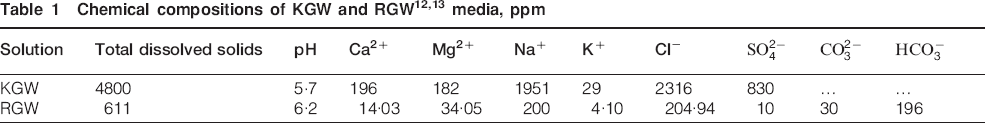
The media used for corrosion testing include DM water solution at pH 1, 5 and 8 (designated in entire text as pH 1, pH 5 and pH 8), simulated Kalpakkam ground water (KGW)11 and Rajasthan ground water (RGW) media.12 The pH value of simulated test solution was obtained by adding appropriate concentration of HCl and NH4OH. The typical compositions of KGW and RGW are shown in Table 1.


Specimen preparation
Metal waste form alloy thus prepared was cut into pieces of 10×10×5 mm dimension and then ground to 600 grit SiC emery paper on all sides. These specimens were then mounted in an epoxy resin with a brass rod for electrical connection. The exposed surfaces of the mounted specimens were ground to 1000 grit SiC emery paper and then polished to 1 μm diamond finish for corrosion studies. The edges of the sample were covered by corrosion resistant lacquer that will prevent the crevice attack at sample/mount interface. All the polished specimens were ultrasonically cleaned in acetone before the corrosion testing.
Microstructural study
The detailed microstuctural study of MWF alloy was carried out using scanning electron microscopy (SEM) in backscattered electron (BSE) mode after etching the samples in 10% ammonium persulphate (NH4HSO4) solution at 2 V up to 1·5 min. The local area compositions were studied using energy dispersive X-ray (EDS) analysis. The lattice phases present in the MWF alloy were studied by X-ray diffraction (XRD) analysis. X-ray diffraction data were collected from a STOE powder diffractometer using Cu Kα radiation and the data were analysed with the help of JCPDS software. The surface morphologies of these specimens were observed by SEM and atomic force microscopy (AFM) after formation of passive film and potentiodynamic polarisation testing in different electrolyte media.
Electrochemical testing for corrosion
Electrochemical techniques have been employed to understand the corrosion behaviour of MWF alloy in different simulated ground water media.
Potentiodynamic polarisation studies
The corrosion resistance properties of MWF alloy in different simulated ground water media were evaluated by potentiodynamic anodic polarisation studies. All the potentiodynamic polarisation experiments were carried out at room temperature using the five neck ASTM standard electrochemical cell consisting of three electrodes: reference electrode (Ag/AgCl in saturated KCl), counter electrode (Pt) and working electrode (specimen). Solartron 1287 electrochemical interface was used for the polarisation experiments. The potentiodynamic anodic polarisation experiments were carried out at a scan rate of 10 mV min−1 and polarisation was continued till the breakdown of transpassive potential. Three sets of experiments were conducted for each medium and all the polarisation plots were reproducible.
Electrochemical impedance spectroscopy (EIS) studies
The EIS measurements were carried out using a Solartron 1255 frequency response analyser and Solartron 1287 electrochemical interface. The experiments were carried out for MWF alloys in the frequency range from 0·01 Hz to 100 kHz by superimposing an AC voltage of 10 mV amplitude at open circuit potential in pH 1, pH 5, pH 8, KWG and RGW media. The EIS results were interpreted using simple electrical equivalent circuit (EEC)13 of one time constant and this model provides accurate fitting of the experimental impedance data. The circuit description consists of the arrangement of {R S(CPE||R P)} elements, where R S is the solution resistance, CPE is the constant phase element in parallel connection with R P, which is the polarisation resistance at the interface. The circuit element values were obtained by fitting the experimental impedance data using Zview version 2.6 software (Scribner Associates Inc., Southern Pines, NC, USA). The impedance expression of CPE14 is given by Z CPE = 1/[T(jω)n], where ω is the angular frequency, T and n are frequency independent fit parameters, j = (−1)1/2 and ω = 2πf, where f is the frequency in Hz. Constant phase element has been used in the present investigation to obtain better fit for experimental data and this will represent the capacitance of the passive oxide layer. Three sets of experiments were conducted for each medium and EIS measurements under all conditions were reproducible.
Electrical equivalent circuits do not provide sufficient insight into the reaction pathway as they are elemental analogues and not models.15 The reaction mechanism analysis is a method where a mechanism is proposed to derive the impedance from the rate of elementary reaction.15 – 17 However for the present work, authors have used EECs to fit the experimental values.
Results and discussion
Microstructural evaluation
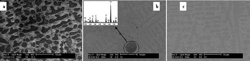
Backscattered electron mode SEM image of the MWF alloy along with its EDS spectra after electrochemical etching is shown in Fig. 1. The BSE microstructure (Fig. 1a) of the MWF alloy revealed the presence of two different phases: one dark and the other bright. The detailed elemental analyses by EDS revealed that the dark phase contains Fe, Cr and Ni as major elements and Mo as minor element, indicating the presence of solid solution phases of the D9 SS alloy. However, in the bright phase along with Fe, Cr and Ni, Zr was present as major element whereas concentration of Ni is comparatively more at bright phase. Different phases present in the MWF alloy have also been characterised by XRD analysis as shown in Fig. 2. The results showed typical peaks of D9 SS alloy along with peaks of Zr intermetallic phases of NiZr, Ni3Zr, Ni7Zr2, Fe3Zr, FeZr2 and Fe2Zr. Pure Zr was not found and it appeared in the form of Zr based intermetallics which were seen as bright phase in the microstructure. The high intensities of Ni in bright phase were due to higher solubility of Ni in NiZr compared with Fe.18 Nickel is also an austenite stabiliser and Abraham et al.19 reported that Zr combines with iron, chromium, nickel and other elements to form Laves and other intermetallics. These intermetallics are strong sink for the austenite stabiliser like nickel.
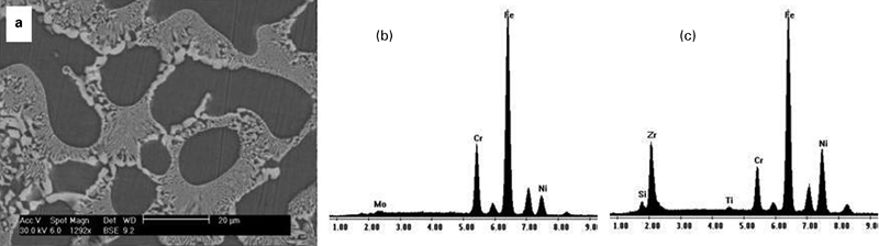
a BSE mode SEM image, b EDS for dark regions and c EDS for bright regions of MWF alloy
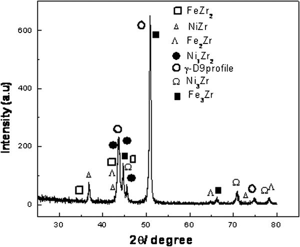
X-ray diffraction pattern of MWF alloy
Electrochemical corrosion studies
Potentiodynamic polarisation study
The potentiodynamic anodic polarisation plots of MWF alloy in different simulated ground water media are shown in Fig. 3. The polarisation results did not show much variation for the breakdown potential E BP values in pH 5, pH 8 and RGW, but in pH 1 and in KGW showed lower E BP values. In pH 1 and RGW, the current densities were higher than the others. Lowering of breakdown potential can occur due to the presence of higher Cl− ion content in solution which was also revealed by pitting attack on the specimen surface with well defined pitting potential E P.20 Both pH 1 and KGW media showed lower breakdown potential due to the presence of higher Cl− ion which is responsible for the pit formation on the surface. Whereas, in pH 5 and pH 8, the conditions were mild acidic and mild basic respectively, the transpassive dissolution started after attaining the corresponding E BP. In RGW, as the mineral concentration was very low, especially Cl− ion content, higher E BP was obtained. Further, in RGW higher current density was noticed due to thinner hydrated passive film21 formation compared with KGW.
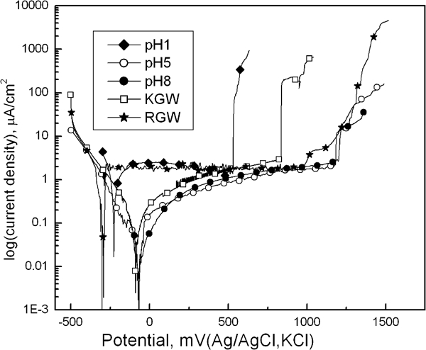
Potentiodynamic polarisation plots of MWF alloy in different media
Electrochemical impedance spectroscopy
The Bode plots of EIS analysis of MWF alloy in different simulated ground water media are shown in Fig. 4a and b. In the frequency versus impedance plot (Fig. 4a), at higher frequency the MWF alloy showed low impedance magnitude whereas at lower frequency a significant increase in the impedance magnitude was observed. At higher frequency, since the interfacial capacitance was predominant, only solution resistance contributed to the complex impedance. However at lower frequency, the interfacial resistance and the reactance contributed to the complex impedance.22 From Fig. 4a, it can be seen that at a frequency range of 1-10−2 Hz the increase in the impedance was prominent. In pH 8 and RGW, higher value of complex impedance was observed compared with pH 1, pH 5 and KGW. Chloride ion has high tendency to adsorb on the surface of the film and then lower the film stability by replacing the water molecules from hydrated passive film.23 The replacement of Cl− ion at the bridge position resulted in the formation of soluble chloride metal complex, with which metal ions were removed from the film oxide.20,23 Owing to the presence of Cl− ion, at low frequency the impedance value became lower in pH 1, pH 5 and KGW compared with pH 8. But in RGW, higher value of impedance was obtained due to the presence of Ca, Mg,  and
and  which form insoluble sulphate and carbonate layer on the surface.24 In Fig. 4b, the phase angle obtained at higher frequency was nearly zero and with decreasing frequency the phase angle increased. A distinct phase shift was also observed in different media. Most likely, the marginal shift of phase angle value depended on surface adsorption of electrolyte.22,25 In pH 5 and pH 8, the presence of such minerals was very low and hence narrower shift of phase angle was seen due to less surface adsorption. However in pH 1, KGW and RGW, the wider shift of phase angle could be observed. Though in RGW, the width of phase shift was quite lesser than other solution, the value of theta was quite higher, indicating the formation of a stable adsorbed film as an insoluble layer on the surface.21
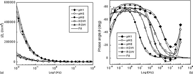
Bode plots of EIS of MWF alloy in different media
Surface morphology after polarisation
The secondary electron mode SEM images of MWF alloy after polarisation in different media are shown in Fig. 5. The surface after polarisation in pH 1 (Fig. 5a) revealed a contrast between dark and bright phases with higher transpassive dissolution. After polarisation in pH 5, pH 8, KGW and RGW, the contrast between the dark and bright phases was negligible. The transpassive dissolution in those media was comparatively low.20 However, after polarisation in KGW (Fig. 5b), the surface revealed the formation of pits with dendritic appearance. The EDS scan (Fig. 5b) in this dendritic area revealed the presence of Na, K, Ca, Cl along with Fe, Cr, Ni and Zr whereas at other places the presence of Na, K, Ca or Cl was not observed. This indicated that the deposition of salt was present only in the dendritic area. After polarisation in pH 5, pH 8 and RGW, the surface indicated very low transpassive dissolution with minimum localised attack (Fig. 5c).
Secondary electron mode SEM images of MWF alloy after polarisation
The AFM images of MWF alloy after passivation and polarisation in different media are shown in Fig. 6. The surface morphologies (Fig. 6a) of MWF alloy passivated in pH 5 and pH 8 revealed the smooth topography with minimum surface aggregation. The surface passivated in KGW (Fig. 6b) revealed the formation of thick salt deposit while in RGW (Fig. 6c) the deposition was comparatively thinner. The thicker passive film in KGW revealed the presence of higher concentration of soluble minerals (Table 1) compared with other media. The deposited layer on the MWF alloy surfaces acted as thin film insulating layers which prevented leak currents, unspecific adsorption and surface decomposition in aqueous electrolyte. 23 23,26 The thicker the deposited layer, the higher the film resistance. Though in KGW film thickness was more, due to the presence of higher concentration of Cl− ion, the film became unprotective by the formation of soluble chloride complex and thereby film resistance decreased.23
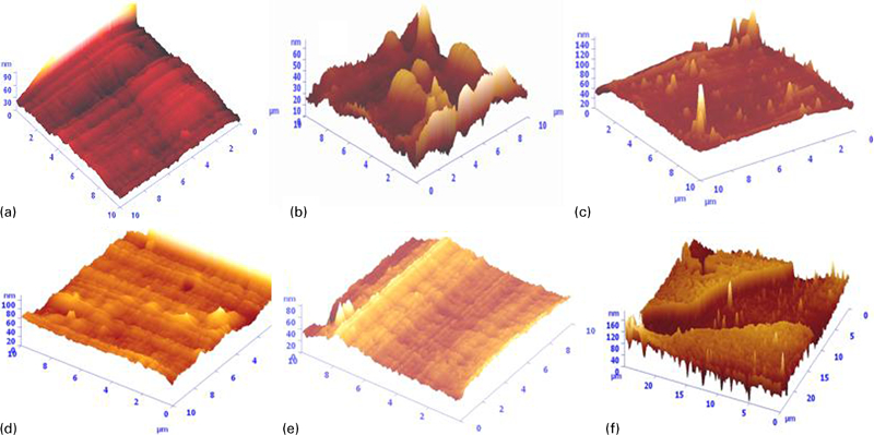
Images (AFM) of MWF alloy after passivation and polarisation in different media
The AFM images indicated the presence of micropits on the exposed surfaces which were polarised in KGW, and in pH 5, pH 8 and RGW (Fig. 6d and e). However, surfaces polarised in KGW (Fig. 6d) showed salt precipitation along with pit formation. There was little or no pit formation on the surfaces polarised in pH 5, pH 8 and RGW. The AFM topography of the MWF alloy after polarisation in pH 1 (Fig. 6f) exhibited unique topography with two distinct phases. One phase was at a higher elevation while the other phase was at a lower valley. The elevated phase in the AFM morphology corresponded to the bright phase obtained in the SEM images and the lower valley corresponded to the dark phase. This indicated that after polarisation in pH 1, dark phase had higher rate of dissolution than the bright phase. The Zr rich intermetallic phases showed lower dissolution and minimum pit formation.13
Conclusions
The corrosion behaviour of MWF alloy with D9 SS and 8·5 wt-% Zr was studied in different simulated ground water media for understanding the corrosion issues in geological disposal. The following conclusions could be drawn from the present investigation.
From the microstructural study, it was revealed that Zr forms intermetallic precipitation in the MWF alloy. These intermetallics are strong sink for austenitic stabiliser.
Metal waste form alloy formed stable hydrated passive film in RGW but in pH 1 and KGW the film stability was lower due to the formation of soluble chloride complex.
Electrochemical impedance spectroscopy study showed that MWF alloy in pH 1, pH 5 and KGW revealed lower impedance due to Cl− ion adsorption but in RGW it showed higher impedance value due to the formation of insoluble Ca and Mg sulphate, and carbonate passive film.
Surface morphology of MWF alloy after polarisation in pH 1 revealed uniform metal dissolution and in KGW the formation of pits and scattered salt deposition was observed. However, after polarisation in pH 5, pH 8 and RGW, very low transpassive dissolution was noticed.
Therefore, lower pH and chloride content in ground water appear to have more corrosion effect compared with neutral pH and scale forming ground waters. However, in all the different simulated ground water conditions, the severity of corrosion was less and the MWF alloy showed better corrosion resistance properties.
Footnotes
Acknowledgements
The authors gratefully acknowledge Dr G. Balachandan of DMRL, Hydrabad for casting the alloy, Mrs C. Sudha, PMD, MMG, IGCAR, Kalpakkam for SEM studies and Dr G. Panneerselvam, FChD, for XRD study.