
Abstract
The effect of an Excimer laser treatment on the corrosion resistance of friction stir welds in AA2024-T351 has been studied by means of electrochemical techniques and immersion tests. The results show a decrease in anodic and cathodic reactivity in the weld region after the laser treatment, achieved due to the formation of a 3-5 μm thick corrosion resistant layer. Immersion tests in 0·1M NaCl confirm that the presence of the treatment decreases the severity of corrosion attack. However they also show that, if the laser layer is damaged by a scratch, corrosion occurs preferentially in the scratch area. Delamination of the laser treated layer can also occur as a consequence of corrosion propagation during the exposure of laser treated samples.
Introduction
Since its introduction in 1991,1 friction stir welding (FSW) has increasingly caught the interest of the aeronautical industry, which has been considering the possibility of replacing conventional riveted joints with friction stir welded joints. This technology offers the opportunity to manufacture high quality welds in the traditionally poorly-weldable high strength aluminium alloys of the 2XXX and 7XXX series, with significant advantages over riveting. In the aerospace industry, FSW has been used with success in joining primary structures in the Eclipse 500 jet,2 and will be applied to join external fuel tanks in the NASA Space Shuttle.3 In high-integrity industries such as the nuclear industry, FSW will be employed to manufacture corrosion resistant copper canisters for the containment of radioactive waste.4
In the last years, a number of studies have been performed to characterise the quality, strength, fracture toughness, fatigue, corrosion and stress corrosion cracking resistance of friction stir welds, and the results have been in most cases encouraging. A review of the findings emerged so far is reported by Mishra and Ma.5
One of the primary concerns about the applicability of FSW in the aircraft is the corrosion performance of the welds: the thermal cycle produced by welding leads to significant changes in the microstructure of the metal, which generates enhanced corrosion susceptibility. Several studies have shown a decrease in corrosion resistance in the weld region of FSW manufactured in 2XXX and 7XXX alloys,6 – 28 and this causes concerns related to the corrosion-fatigue of FSW components, as the onset of localised corrosion in aluminium alloys is known to be able to decrease this parameter.29
Three main microstructural regions are usually identified in a friction stir weld: nugget, thermomechanically affected zone and heat affected zone (HAZ). The weld process parameters (mainly rotational and traverse speed of the FSW tool piece) influence which of these regions shows the greatest corrosion attack. Work on AA2024-T351 17 17,18 showed the correlation between welding parameters and precipitation of the age-hardening precipitate (S phase) and related the corrosion behaviour of the welds to the local thermal cycle produced in each weld region as a consequence of different process conditions.
Given the increased susceptibility of the weld region, it is important to improve the corrosion performance of friction stir welds by the use of appropriate process conditions or post-treatments. The choice of appropriate process parameters has been proven to be a valuable tool in tailoring the properties of a weld, but has been unable to prevent corrosion of the joint. 17 17,18 The use of cryogenic fluids to cool the weld region during welding has also shown some limited ability in preventing sensitisation of the weld region. 19 19,20 The use of post-weld heat treatments to increase and homogenise the corrosion resistance of the weld, on the other hand, has shown that abnormal grain growth can occur if the weld nugget is exposed to solution heat treatment temperatures 30 30,31 and that artificial aging after welding is unable to induce microstructural changes in the heat affected zones of the weld.26,32 – 34 Furthermore, the application of such thermal treatments can be limited by practical considerations related to the size of the components to be treated.
Among possible post-treatments, laser surface melting (LSM) can be considered. Laser surface melting is able to increase the corrosion resistance of aluminium by dissolving the detrimental constituent particles present in commercial alloys. The constituent particles, rich in relatively noble elements such as Cu and Fe, increase the cathodic reactivity by acting as catalytic sites for oxygen reduction 35 35,36 and at the same time act as preferential sites for pitting initiation37 so that their removal can produce a noticeable increase in corrosion resistance. A review of the application of LSM to aluminium alloys was produced by Watkins et al.38
On parent material, increase in corrosion resistance has been obtained by treating aluminium alloys with pulsed lasers such as Excimer lasers,39 – 51 in which the short duration of the thermal cycle induced by laser irradiation leads to limited microsegregation in the molten and resolidified layer.47 – 51 In contrast, relatively low corrosion resistance has been obtained with continuous wave (CW) lasers such as CO2 and CW-Nd:YAG lasers, as, in this case, the longer interaction times of the laser beam with the surface produces significant microsegregation of the alloying elements.52 – 58 In particular studies on AA2024 and AA2014 have shown the formation of a fine columnar or dendridic structure in which significant microsegregation of Cu was observed, leading to the formation of a cathodically reactive surface.52 – 57 The microsegregation is detrimental to the corrosion performance of the surface as the formation of galvanic cells between different phases is known to be able to accelerate the degradation of the less noble phase.
Initial tests investigating the use of LSM to increase the corrosion resistance of friction stir welds has been reported.6 – 9,59,60 Apart from increasing the corrosion resistance of the parent material and of the weld region, the use of LSM to increase the corrosion resistance of welds might offer the ulterior benefit of reducing galvanic coupling effects between different weld regions that can occur if wetting of the metal with a relatively conductive electrolyte takes place.
This paper discusses the application of laser treatment with Excimer laser to increase the corrosion resistance of friction stir welds in AA2024-T351. A companion article describes the effect of laser treatment on FSW in AA7449-T7951.61 These papers summarise part of the results obtained in a PhD project62 that studied the corrosion resistance of friction stir welds in aerospace aluminium alloys and investigated the use of LSM to improve their corrosion resistance.
Material and methods
AA2024-T351 laser surface melted friction stir welds were supplied by BAE SYSTEMS in the form of 4·0 mm thick plates; the nominal chemical composition of AA2024 is reported in Table 1.63 Friction stir welding was performed with a Triflute carbon steel tool piece at rotation speed of 486 rev min−1 and a traverse speed of 195 mm min−1. Mechanical milling of 0·2 mm from the weld surface was performed before laser treating the welds to remove the characteristic friction stir weld ‘crown’.
Nominal chemical composition of AA2024,63 wt-%
Laser surface melting was performed in BAE SYSTEMS with a XeCl Excimer laser (wavelength λ = 308 nm) on the surface of AA2024-T351 FSW plates (L-LT plane). The laser was operated at a fluence of 5 and 10 J cm−2. These two treatments were obtained respectively in a 6×3 and a 3×3 raster scanning mode62 in order to obtain 18 and 9 pulses per unit area and hence the same integrated fluence (90 J cm−2). In this article, the two treatments will be denoted as ‘5 J 6×3’ (5 J cm−2 6×3 raster) and ‘10 J 3×3’ (10 J cm−2 3×3 raster). The laser treatment was performed in air after organic degreasing of the plates with iso-propanol. Appropriate degreasing was found to be important as external species (for example from the lubricant used during previous rolling operations) were found to be potentially incorporated in the treated layer if not adequately removed. The laser focusing system comprised of microarray of lenses that produced a spot size of 1·5×1·5 mm.
The morphology of laser treated FSW was characterised with SEM of surface and cross-section. The cross-sections were prepared via cutting with a Struers ‘Accutom-5’ precision machine, cold mounting in a Met Prep ‘Tri-Hard’ epoxy resin and polishing to 1 μm with Struers ‘DiaDuo’ diamond suspension. Before examination, a thin carbon coating was also deposited on the sample in order to eliminate charging effects at the metal/resin interface and make the sample electrically conductive. For this analysis a JEOL 7000F field emission gun scanning electron microscope was used in secondary electron and backscattering mode at an accelerating voltage of 15 kV. Chemical analysis of the laser treated material was also investigated using energy dispersive X-ray spectroscopy (EDX), performed at an accelerating voltage of 15 kV with a JEOL 6400 SEM equipped with a Noran Instruments EDX detector.
The electrochemical reactivity of laser treated and untreated welds was tested in a 0·1M NaCl solution in a microcapillary cell. In this set-up, a droplet of solution of controlled dimensions is positioned via a pipette tip on the area to be tested. The pipette is physically connected to a solution reservoir where both reference electrode (Ag/AgCl) and counter electrode (platinum wire) are accommodated. Details on the use of this technique are reported elsewhere. 6 7 17 6,7,17,18 For all the tests performed in this work, a pipette tip with a contact area of 1·2 mm2 was used. Anodic and cathodic polarisation tests were performed on selected areas of laser treated and untreated welds; the tests were performed on the weld surface in a scan perpendicular to the welding direction in order to obtain a map of the electrochemical reactivity as a function of position across the weld line. Anodic and cathodic scans were performed separately on different spots after 300 s of free corrosion in which the open circuit potential (OCP) was monitored. The scan started at the OCP (±10 mV) and proceeded to higher (anodic polarisation) and lower (cathodic polarisation) values of the potential. Only the cathodic polarisation measurements performed on the laser treated ‘10 J 3×3’ treatment started from a value of the potential different from the OCP, which was −800 mV(Ag/AgCl). The sweep rate was 1 mV s−1. The surface preparation involved polishing to 1 μm 3 days before testing for untreated welds and 30 s immersion in concentrated nitric acid immediately before testing for the laser treated welds. Just before testing, untreated and laser treated weld samples were rinsed with deionised water, ethanol and air dried. Nitric acid dipping was adopted as preparation procedure for the laser treated material since the normal grinding/polishing preparation procedure would have removed the laser treated layer. Separate tests (not shown) confirmed that difference in surface preparation between laser treated and untreated material did not affect the outcome of these measurements.62
Immersion tests in Cl containing electrolyte were performed to verify whether the presence of laser treatment on AA2024-T351 FSW would reduce the severity of corrosion and to understand whether the presence of scratches in the treatment would be accompanied by significant corrosion of the substrate. Samples about 1 cm wide and 8 cm long (for an overall area of 8 cm2) were scratched and immersed in corrosive electrolyte. The immersion was carried out in two independent tests for 5 and 20 days in a naturally aerated 0·1M NaCl solution on untreated and laser treated welds. The samples were covered in several layers of ‘Stopping-off’ lacquer to expose only the L-LT surface. The immersion was performed in a beaker immersed in a thermal bath at a temperature of 25°C; deionised water was periodically added to the system in order to keep the solution volume and the electrolyte concentration constant with time. The samples were scratched across the weld region perpendicular to the welding direction. Both untreated and laser treated welds were scratched for consistency. The scratch was produced few days before immersion in the electrolyte with a sharp stainless steel tool and was estimated to be ∼15 μm deep after profilometric analysis. As the depth of the LSM layer was only 3-5 μm thick, the scratch was deep enough to expose the substrate. On the corroded samples, 2D analysis was performed via optical and SEM microscopy of surface and cross-section and three-dimensional (3D) analysis was performed with X-ray microtomography (ex situ samples). Before examination, removal of corrosion products was carried out in some cases with immersion for 2 min in concentrated nitric acid.
Open circuit potential measurements were also performed on untreated, intact laser treated and scratched laser treated samples to evaluate the effects of galvanic coupling between laser treated layer and scratched area (substrate). The dimension of these samples was ∼9 cm2, similar to that of scratched weld samples. This ensured similar anode/cathode ration in both experiments. The tests were performed for 24 h in naturally aerated 0·1M NaCl in a beaker containing 500 mL of solution. The data acquisition rate was set to 1 measurement every 100 s. The samples were covered with several layers of ‘Stopping-off’ lacquer in order to expose only the scratched L-LT surface (laser treated or untreated). For these measurements, the reference electrode was a saturated calomel electrode. The temperature was controlled at values of 25°C with a water bath.
X-ray microtomography was performed at the Materials Science beamline of the Swiss Light Source at the Paul Scherrer Institut in Switzerland.64 This technique represents a powerful tool to image the microstructure of relatively small volumes of material in three dimensions and was used to understand the mechanism of corrosion propagation in laser treated material. The acquisition apparatus comprised a 28 μm thick Ce doped YAG scintillator. The beam energy was set to 17·5 keV, the exposure time to 2 s. Seven hundred and twenty-one radiographs were acquired in a complete 180° rotation around the sample axis at regular angles of ∼0·25°. The acquisition window of the camera was set to 1024×1024 pixels in 2× ‘binning mode’, resulting in a theoretical pixel size of ∼1·4 μm. The 3D information was reconstructed with traditional filtered (Butterworth) backprojection algorithm. Sample ‘pins’ (parallelepipeds with base dimension of about 700×700 μm) were cut with a Struers ‘Accutom-5’ machine and glued with ‘Araldite’ glue in stainless steel holders. Ex situ samples were cut out from nugget, HAZ and parent material of laser treated welds after immersion test, as described in the previous paragraphs. These samples were analysed in order to investigate corrosion propagation in damaged LSM layers. Samples for in situ experiments were cut from nugget, HAZ and parent material of laser treated welds and exposed in situ to a 0·1M NaCl solution in a radiation transparent silicone rubber tube. In this case, the cut surfaces of the sample were exposed to the corrosive solution in addition to the laser treated surface. The samples were glued to the stainless steel holders with a continuous layer of glue in order to prevent the simultaneous exposure to the electrolyte of aluminium and stainless steel which would have resulted in undesired galvanic coupling effects. On each in situ sample, analysis before and during immersion (after 24 h) was carried out. These samples were analysed to investigate the mechanism of corrosion propagation in laser treated layers.
Results
Laser treated layer morphology
Figure 1a shows an optical micrograph of a ‘10 J 3×3’ laser treated friction stir weld; the characteristic pattern produced on the metal surface after the LSM treatment is visible from the magnified view displayed in Fig. 1b. Higher magnification SEM images of the treated surface show the absence of the characteristic micrometre sized constituent particles found in AA2024-T351 (Fig. 1c and d). Scanning electron micrographs of the cross-section of the same sample (‘10 J 3×3’) show partial dissolution of the bright, micrometre sized constituent particles and formation of a 3-5 μm thick precipitate free layer in any weld region (Fig. 2a–c).
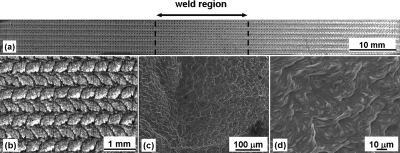
Excimer laser treated AA2024-T351 FSW (‘10 J 3×3’ treatment); a, b optical micrographs showing surface morphology after treatment; c, d micrographs (SEM) (secondary electron mode)
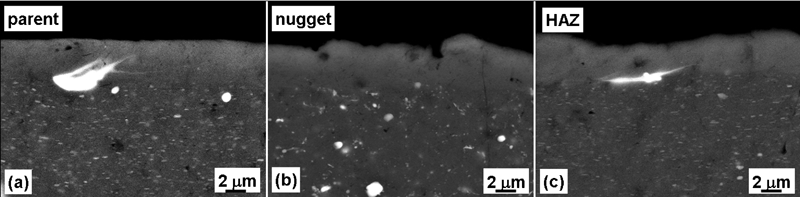
Cross-section SEM images (backscattered electron mode) showing partially melted constituent particles in LSM layer produced on a parent material, b FSW HAZ and c FSW nugget for ‘10 J 3×3’ treatment on AA2024-T351 laser treated FSW
Figure 3 shows backscattered SEM images showing a comparison between ‘10 J 3×3’ laser treated (Fig. 3a), ‘5 J 6×3’ laser treated (Fig. 3b) and untreated (Fig. 3c) parent material samples. The ‘5 J 6×3’ sample shows bright patches which are likely to be partially dissolved constituent particles (bright in backscattering mode). These are not visible in the ‘10 J 3×3’ sample, suggesting that they have been more efficiently dissolved. Similar results where found in the HAZ of the welds, but not in the nugget, in which particle dissolution was complete also for the ‘5 J 6×3 sample’ (not shown).
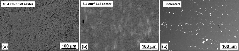
Images (SEM) (backscattered mode) showing surface appearance of a ‘10 J 3×3’ treatment, b ‘5 J 6×3’ treatment and c untreated metal on AA2024-T351 parent material
Figure 4 shows the elemental composition of the ‘10 J 3×3’ LSM layer and the untreated matrix in the parent material region after EDX analysis. The results show that the LSM layer and the matrix exhibit similar elemental composition; although there is considerable scatter, there is some evidence for slight enrichment in Cu in the LSM layer.
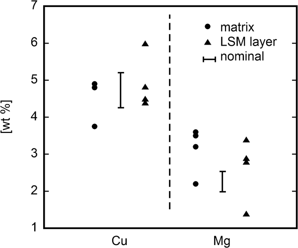
Elemental analysis (EDX) of untreated and laser treated (‘10 J 3×3’) AA2024-T351 parent material. Nominal chemical composition of alloy (3·8-4·9 wt-%Cu, 1·2-1·8 wt-%Mg, 0·25 wt-%Zn) is also plotted
Electrochemical characterisation of laser treated welds
The electrochemical reactivity of the LSM layer produced on the AA2024-T351 weld was tested with anodic and cathodic polarisation tests performed with microcapillary cell. Typical anodic polarisation curves obtained for the parent material region of the laser treated and untreated welds are shown in Fig. 5a (‘5 J 6×3’ treatment) and Fig. 5c (‘10 J 3×3’ treatment). It is evident that, for both ‘5 J 6×3’ and ‘10 J 3×3’ samples, the laser treatment can improve the corrosion resistance of the alloy by increasing the breakdown potential. After laser treatment, the surface exhibits relatively wide passive regions in 0·1M NaCl, which are not present in the untreated material. Particularly low passive current density is shown by the ‘10 J 3×3’ treatment. The scatter in the values of breakdown potential measured with microcapillary cell is typical of this technique and is associated with the reduced area tested in these measurements compared with conventional electrochemical measurements.37
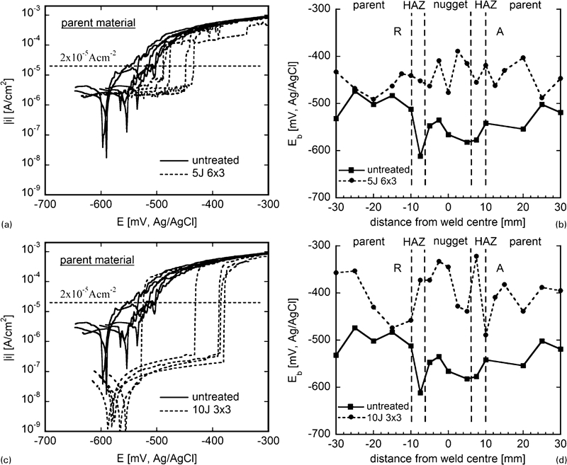
Anodic reactivity of laser treated and untreated FSWs in 0·1M NaCl (sweep rate 1 mV s−1). a, c typical anodic polarisation curves in parent material comparing the reactivity of the laser treatment (dipped in nitric acid) with the reactivity of the untreated metal (polished); a ‘5 J 6×3’ treatment; c ‘10 J 3×3’ treatment. b, d nominal breakdown potential (E b) at i = 2×10⁻⁵ A cm−2 as a function of position relative to the weld centre for laser treated (dipped in nitric acid) and untreated FSW (polished); b ‘5 J 6×3’ treatment; d ‘10 J 3×3’ treatment. A = ‘advancing’ side of the weld; R = ‘retreating’ side of the weld
In order to compare the reactivity across the weld, a nominal ‘breakdown potential’ (E b) was selected as the potential where the value of the anodic current density reached 2×10⁻⁵ A cm−2. Values of E b as a function of position across the weld line are shown in Fig. 5b (‘5 J 6×3’) and Fig. 5d (‘10 J 3×3’). In both these plots the untreated weld is shown as a solid line, which lies below the broken line that corresponds to the laser treated welds. Despite the scatter in the values of the breakdown potential, the separation between the curves measured on untreated and laser treated welds demonstrates that laser treatment confers an improvement in corrosion resistance, as the breakdown potential is significantly increased after the laser treatment. Furthermore, the breakdown potential is fairly consistent across the entire weld for the laser treated surfaces, but is lower in the weld region for the untreated weld, showing the greatest susceptibility to anodic dissolution of this region if no post-weld treatment is carried out.
Typical cathodic polarisation curves measured in the parent material region of laser treated and untreated welds are shown in Fig. 6a (‘5 J 6×3’) and Fig. 6c (‘10 J 3×3’). It is clear that the laser treatment can increase the corrosion resistance of the alloy by reducing the cathodic reactivity. To show this effect on a weld, the value of the cathodic current density measured at a potential of −900 mV(Ag/AgCl) were plotted as a function of position across the weld line for laser treated and untreated welds. This is shown in Fig. 6b (‘5 J 6×3’) and Fig. 6d (‘10 J 3×3’). The laser treated material (broken line) shows lower cathodic reactivity in the whole weld region and more uniform reactivity in comparison with the untreated weld (solid line), where a cathodic current density peak is observed in the weld nugget.
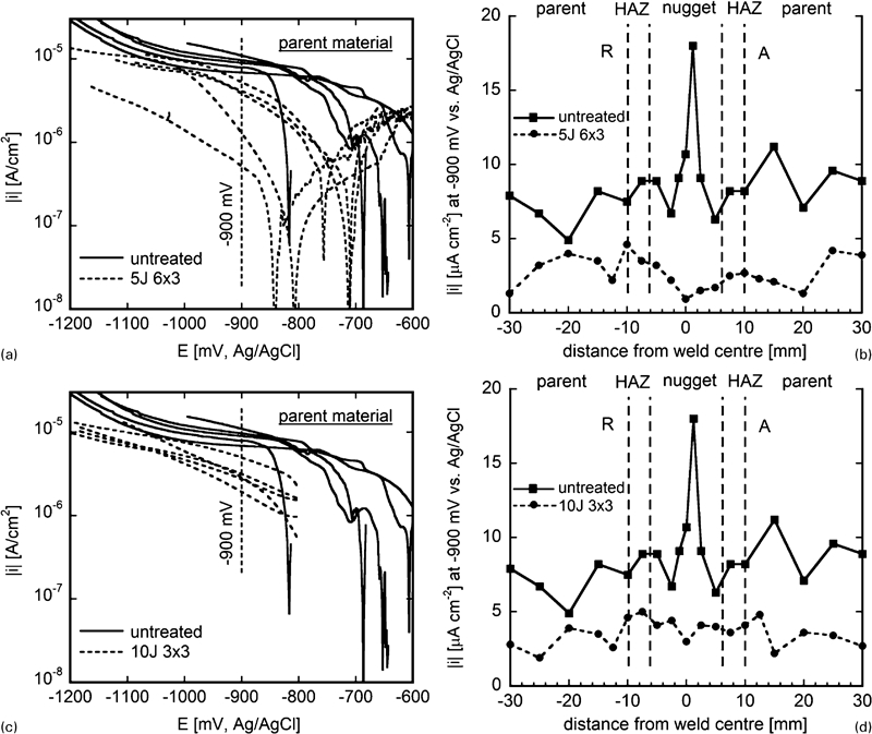
Cathodic reactivity of laser treated and untreated FSWs in 0·1M NaCl (sweep rate 1 mV s−1). a, c typical cathodic polarisation curves (sweep rate 1 mV s−1) for parent material comparing the reactivity of the laser treatment (dipped in nitric acid) with the reactivity of the untreated metal (polished); a ‘5 J 6×3’ treatment; c ‘10 J 3×3’ treatment. b and d cathodic current density at −900 mV(Ag/AgCl) as a function of position relative to the weld centre for laser treated (dipped in nitric acid) and untreated FSW (polished); b ‘5 J 6×3’ treatment; d ‘10 J 3×3’ treatment. A = ‘advancing’ side of the weld; R = ‘retreating’ side of the weld
Optical and scanning electron microscopy examination after immersion in 0·1M NaCl solution
To verify whether the LSM treatment increases the corrosion resistance of 2024-T351 FSWs and to understand whether the presence of potential scratches in the treatment would lead to significant dissolution in the scratched area, immersion for 5 and 20 days of scratched laser treated and untreated welds in 0·1M NaCl solution was performed. Post-immersion analysis was performed both in the scratched area and in areas ‘away’ from the scratch.
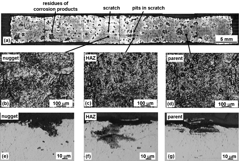
Figure 7a shows the appearance of the untreated weld after 20 days immersion in 0·1M NaCl followed by corrosion product removal in concentrated nitric acid. The weld was found susceptible to pitting, with relatively small and sparse pits in nugget (Fig. 7b and e) and parent material (Fig. 7d and g) and coarser and more numerous pits in the HAZ (Fig. 7c and f). Sparse areas of superficial intergranular corrosion were also detected (not shown). Particularly intense attack was found in the scratched area in the HAZ (Fig. 7c).
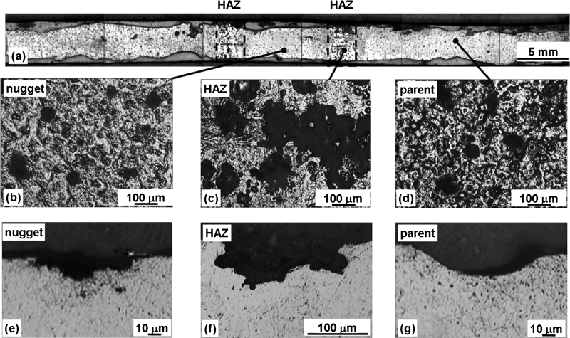
Untreated FSW after 20 days immersion in 0·1M NaCl and removal of corrosion products in concentrated nitric acid: a weld surface micrograph; b–d optical micrographs of surface in nugget, HAZ and parent material respectively; e–g optical micrographs of cross-section showing typical localised corrosion sites in nugget, HAZ and parent material respectively. Note that micrograph f is taken a lower magnification than micrographs e and g
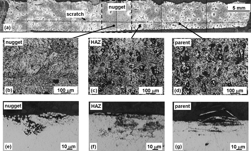
Figure 8a shows the appearance of the ‘10 J 3×3’ laser treated weld after the same test. Residues of incompletely removed corrosion products were still visible after immersion in nitric acid in certain areas of the sample so that optical microscopy was necessary to gain a better evaluation of the extent of corrosion damage. Evaluation of the damage in areas away from the scratch is shown in (Fig. 8b–g). Figure 8c and f shows that there are small corrosion sites in the HAZ (∼50 μm) for the laser treated sample compared with larger sites (>100 μm) for the untreated weld (Fig. 7c and f). The nugget of the laser treated weld was found to be particularly resistant (Fig. 8b). The morphology of damage in the ‘10 J 3×3’ laser treated layer showed shallow areas of attack surrounding central intact areas of micrometric scale. Evidence of delamination of surface layers and sparse areas of intergranular attack were also evident from observation of the cross-section.
Laser treated ‘10 J 3×3’ FSW after 20 days immersion in 0·1M NaCl following removal of corrosion products in concentrated nitric acid: a weld surface micrograph; b–d optical micrographs of surface ‘away’ from the scratch in nugget, HAZ and parent material respectively; e–g optical micrographs of cross-section ‘away’ from the scratch showing typical localised corrosion sites in nugget, HAZ and parent material respectively
The ‘5 J 6×3’ weld (Fig. 9) showed similar reactivity to that exhibited by the ‘10 J 3×3 weld’ (Fig. 8) after 20 days immersion in 0·1M NaCl, with a particularly beneficial effect in the HAZ. However, the number of localised attacks visible in HAZ (Fig. 9c) and parent material (Fig. 9d) was slightly higher than that visible in the same regions of the ‘10 J 3×3’ weld (Fig. 8c and d).
Laser treated ‘5 J 6×3’ FSW after 20 days immersion in 0·1M NaCl following removal of corrosion products in concentrated nitric acid: a weld surface micrograph; b–d optical micrographs of surface ‘away’ from the scratch in nugget, HAZ and parent material respectively; e–g optical micrographs of cross-section ‘away’ from the scratch showing typical localised corrosion sites in nugget, HAZ and parent material respectively
Analysis of the scratched area of the ‘10 J 3×3’ sample, however, revealed the presence of few relatively large pits in the exposed substrate after 20 days exposure to 0·1M NaCl, especially in the HAZ (Fig. 10a). An independent immersion for 5 days confirmed this behaviour (Fig. 10b) and showed that two relatively large pits developed in the HAZ in these conditions (note that Fig. 10b shows two large pits surrounded by white corrosion products in the HAZ, while the other black spots visible in the samples were not associated with pitting). From surface examination ( Figure 7 Figs. 7c and 10a), the size of the pits developed in the scratched HAZ of the ‘10 J 3×3’ laser treated weld were comparable in size with that found in the HAZ of the untreated weld. This was not the case for the ‘5 J 6×3’ treatment, in which examination of the scratched area after 20 days (Fig. 9a) and 5 days (Fig. 10c) did not show preferential development of pitting in the scratched HAZ.
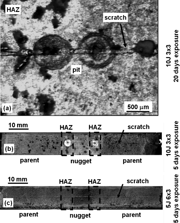
Optical micrographs showing attack developed in the scratched area of the laser treated welds after immersion in 0·1M NaCl: a high magnification micrograph showing pits developed in the ‘10 J 3×3’ laser treated FSW after 20 days immersion (see Fig. 9a); b pits developed in the HAZ of ‘10 J 3×3’ laser treated FSW after 5 days immersion; c appearance of the ‘5 J 6×3’ laser treated FSW after 5 days immersion. Note that the 5 and 20 days immersion tests were performed on different samples. Note that on b and c corrosion products were not removed
Open circuit potential measurements on ‘10 J 3×3’ laser treated and untreated parent were employed to explain the behaviour of the scratched laser treated material. Measurements on intact and scratched laser treated parent material and on untreated parent material in 0·1M NaCl are shown in Fig. 11. The measurements show higher OCP of the intact laser treated material in comparison with the untreated and scratched laser treated material.
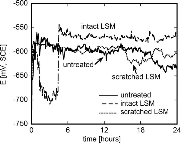
Open circuit potential of untreated, scratched laser treated (‘10 J 3×3’) and intact laser treated (‘10 J 3×3’) parent material specimens during immersion in 0·1M NaCl
Apart from showing the characteristic morphology and size of localised attack after immersion in corrosive electrolyte, inspection of corroded cross-sections revealed a certain tendency of the laser treated layer to delaminate from the substrate as a consequence of corrosion propagation (e.g. Figure 8 Figs. 8g and 9g). This behaviour can lead to partial removal of the laser treated layer from the substrate, potentially decreasing the effectiveness of the laser treatment. There was some uncertainty as to whether the delamination observed in the cross-sectional analysis was an artefact of sample preparation. In order to determine whether this was the case, further analysis was carried out though careful sample preparation (slow speed cutting) followed by X-ray microtomography measurements, which are described in the section on ‘X-ray microtomography examination of in situ samples’.
X-ray microtomography examination of ex situ samples
In order to study corrosion propagation in damaged laser treated layers, X-ray microtomography was used to analyse ex situ samples cut out from a scratched ‘10 J 3×3’ laser treated weld after immersion in 0·1M NaCl for 5 days (the weld shown in Fig. 10b). The corrosion products were not removed before examination. Surface observation of the weld had shown formation of relatively large pits in the HAZ and little attack in the rest of the weld. X-ray microtomography was used to gain a better characterisation of the corrosion damage.
Figure 12 shows X-ray microtomography ‘slices’ parallel to the laser treated surface extracted from a 3D reconstruction of a sample cut out from the nugget of the weld. The slices visualise planes at different depths below the surface of the metal. Slices at 3 and 10 μm (Fig. 12a and b) intersect the scratch, which was found to have a depth of between 10 and 20 μm from 3D examination of the tomogram. There was no evidence of any localised corrosion developing from the scratch. Figure 12b and c shows that two relatively small localised corrosion sites (⩾20 μm deep) developed away from the scratch. Similar results were found on a sample cut out from parent material and are consistent with the extent of attack observed after 20 days immersion (Fig. 8b and d).
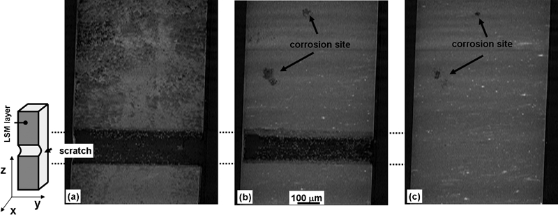
X-ray microtomography ‘slices’ of scratched laser treated (‘10 J 3×3’) AA2024-T351 FSW in the nugget region examined ex situ after immersion for 5 days in 0·1M NaCl. The slices show planes parallel to the laser treated layer at different depths below the surface: a 3 μm; b 10 μm; c 20 μm. Note that the ex situ immersion was carried out on a sample containing both the laser treated weld region and laser treated parent material, from which microtomography samples were extracted. Corrosion products were not removed
Figure 13 shows X-ray microtomography ‘slices’ parallel to the laser treated surface extracted from a 3D volume reconstruction of the a sample cut out from the HAZ of the weld. This sample contained a section of one of the pits shown in Fig. 10b and microtomography examination confirmed that the pit developed in the scratched area and penetrated into the substrate for a depth of about 200 μm. (Note that the depth of the scratch originally produced on the metal was about 10-20 μm.) Figure 13b also shows that significant corrosion attack developed beneath the scratch in areas that looked intact during optical examination. The morphology of the attack found in the HAZ sample, is also shown in the set of micrographs displayed in Fig. 14, which shows X-ray microtomography ‘slices’ perpendicular to the laser treated layer and to the scratch direction.
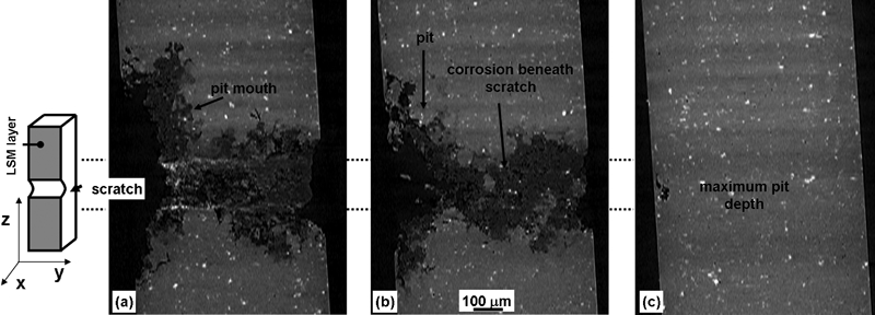
X-ray microtomography ‘slices’ of scratched (‘10 J 3×3’) laser treated AA2024-T351 FSW in the HAZ region examined ex situ after immersion for 5 days in 0·1M NaCl. The slices show planes parallel to the laser treated layer at different depths below the surface: a 15 μm; b 75 μm; c 200 μm. Note that the initial scratch depth was about 10-20 μm and that, apart from the pit visible on the left of the micrographs, significant dissolution occurred beneath the rest of scratch as shown by micrograph b. Corrosion products were not removed
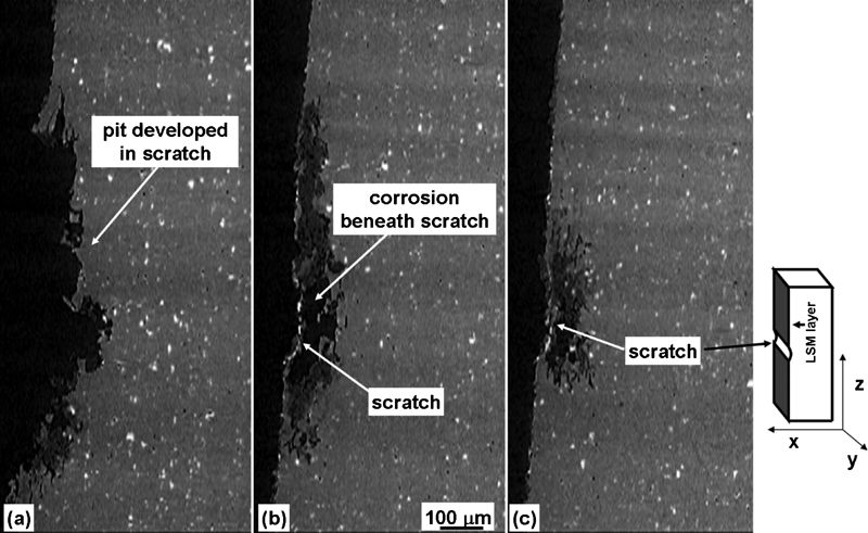
X-ray microtomography ‘slices’ of scratched laser treated (‘10 J 3×3’) AA2024-T351 FSW in the HAZ region after immersion for 5 days in 0·1M NaCl. The slices show planes perpendicular to the laser treated surface and to the scratch direction and show the development of corrosion damage in the scratched area: a slice showing maximum pit depth; b, c slices showing typical attack below the scratch
X-ray microtomography examination of in situ samples
To investigate the delamination effect observed from post-exposure examination of the cross-section (e.g. Figure 8 Figs. 8g and 9g), in situ X-ray microtomography experiments were performed on ‘pins’ carefully cut (slow cutting speed) from the nugget, HAZ and parent material of a ‘10 J 3×3’ laser treated weld. In this case, the cut untreated surfaces were exposed together with the laser treated surface.
Figure 15 shows the same X-ray microtomography ‘slice’ perpendicular to the axis of the pin sample acquired before corrosion exposure (Fig. 15a) and in situ (Fig. 15b) following 24 h exposure of a parent material laser treated sample in 0·1M NaCl. The distribution of constituent particles confirms that the same section of the sample is being observed in both figures. It is evident that delamination of the LSM layer has taken place during corrosion propagation in the laser treated material. By virtue of being an in situ technique, X-ray microtomography was able to confirm that the delamination observed during the analysis of the cross-section was not an artefact of sample preparation but rather it occurred as a consequence of corrosion.
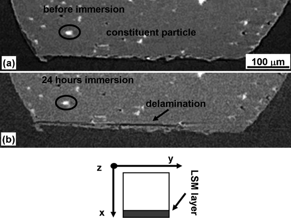
The same X-ray microtomography ‘slice’ of a parent material laser treated sample (‘10 J 3×3’) collected a before immersion and b in situ following immersion for 24 h in 0·1M NaCl. The slice is perpendicular to the pin axis. The distribution of intermetallic particles in the metal confirms that the same slice is being observed in both images
Figure 16 Figures 16 and 17 show the extent of the delamination damage developed after 24 h during in situ exposure, displaying sets of ‘slices’ at different locations along the axis of the sample. These results indicate that delamination can occur in a significant fraction of the laser treated area after 24 h exposure to 0·1M NaCl. The results obtained on HAZ and nugget samples (not shown), however, did not show any sign of delamination after 24 h exposure, suggesting that this phenomenon might take place only on some areas of a laser treated surface. This is consistent with the observations made after 20 days exposure in the same electrolyte (immersion tests), which showed that, although delamination occurred in some areas, it did not occur on the whole sample. An example is shown in Fig. 18, which shows the presence of the laser treated layer adjacent to a localised corrosion site developed after 20 days immersion in 0·1M NaCl in the nugget of a laser treated FSW (the same site shown in Fig. 8e). Although the enlarged image shown in Fig. 18b suggests that some delamination may be occurring in proximity of the localised corrosion site, the right hand side of Fig. 18a shows that the laser treated layer is still largely present on the surface.
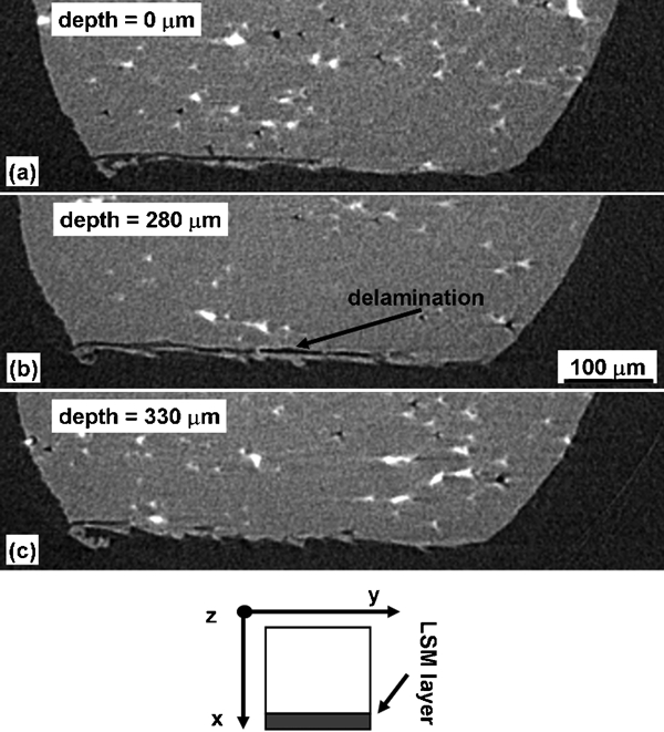
X-ray microtomography ‘slices’ of a parent material laser treated (‘10 J 3×3’) sample collected in situ after immersion for 24 h in 0·1M NaCl. The slices show planes perpendicular to the pin axis direction at different depths from a plane close to the top of the pin (a = 0 μm, b = 280 μm, c = 330 μm)
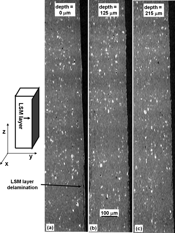
X-ray microtomography ‘slices’ of parent material laser treated (‘10 J 3×3’) collected in situ during immersion for 24 h in 0·1M NaCl. The slices show planes perpendicular to the laser treated layer at different depths from the side of the pin (a = 0 μm, b = 125 μm, c = 215 μm). Delamination of the LSM layer is visible for a significant extent after 24 h immersion in corrosive electrolyte
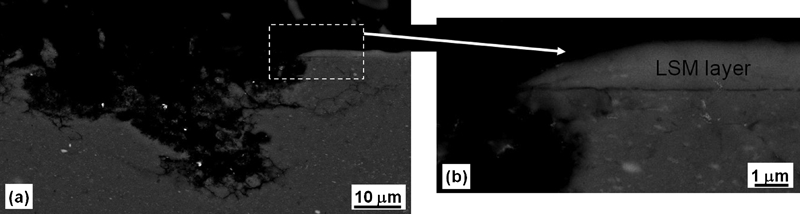
Cross-section SEM images of laser treated ‘10 J 3×3’ AA2024-T351 FSW sample (nugget region) showing the presence of the laser treated layer on the surface after 20 days immersion in 0·1M NaCl
Discussion
Electrochemical measurements ( Figure 5 Figs. 5 and 6) and immersion tests (Fig. 7) indicated a higher corrosion susceptibility of the weld region in comparison with the parent material for untreated AA2024-T351 FSWs, shown by a decrease in breakdown potential and by an increase in cathodic reactivity. These results are in agreement with the findings of other studies that highlighted the decrease in corrosion resistance often found in heat treatable aluminium alloys as a consequence of FSW.6 – 28 In particular, for AA2024-T351, this behaviour was attributed to the changes in precipitation of S phase generated in the weld region as a consequence of the welding process. 17 17,18
Laser surface melting produced the formation of a homogeneous, 3-5 μm thick laser treated layer across weld region and parent material. Thermal dissolution of constituent particles occurred in the LSM weld, leading to the formation of a precipitate free layer on the micron scale. At the micrometre scale (typical of EDX measurements) the chemical composition of the laser treated layer showed some evidence of copper enrichment relative to the matrix of the bulk alloy, which is likely to be associated with the dissolution of copper rich constituent particles. The dissolution of constituent particles was enhanced in the nugget region (Fig. 2b), as in these area the constituent particles are fragmented into smaller pieces by the action of the FSW tool. 17 17,18 The morphology of the laser treated layer observed in this study is consistent to that observed by other studies after LSM aluminium alloys with Excimer lasers,39 – 51 which showed only submicrometre precipitation (usually observed with TEM or high resolution SEM techniques) in laser treated aluminium alloys.47 – 51
Electrochemical measurements indicated that LSM with an Excimer laser can improve the corrosion resistance of AA2024-T351 friction stir welds by decreasing cathodic reactivity and increasing the breakdown potential in weld region and parent material ( Figure 5 Figs. 5 and 6). Furthermore, the electrochemical measurements showed that laser treating the weld can produce homogenisation of the reactivity, with consequent reduction of galvanic coupling effects that could occur if wetting of the metal surface with a continuous, conductive electrolyte takes place.
The increase in corrosion resistance of the laser treated weld was confirmed by immersion tests in chloride solution, which showed that significantly shallower pits formed in the HAZ of the laser treated weld. An increase in corrosion resistance was also observed in other regions of the weld (especially for the ‘10 J 3×3’ treatment), since optical microscopy indicated a lower density and size of pits formed in the laser treated material compared with that observed in the same regions of the untreated weld. A higher density of attack was found in the ‘5 J 6×3’ treatment. However, a comparison of the pit density found on the laser treated welds and the untreated welds was not straightforward owing to differences in surface roughness (the higher roughness of the untreated material makes it difficult to distinguish pits of small size). The reduction in pit density is likely to be associated with the ability of the laser treatment to dissolve some of the constituent particles, which in aluminium alloys are known to be initiation sites for pitting. In the laser treated welds, the morphology of attack observed from examination of the surface (a narrow region of attack surrounding an intact central area) and the evidence of delaminated features in the cross-section suggest that, in the laser treated layer, corrosion initiation may be associated with remnants of incompletely melted constituent particles and areas of delamination of the LSM layer. (Preferential attack around constituent particles is well known in aluminium alloys and is likely to have occurred, at least in the early stages of corrosion, also in the untreated weld). Analysis of the cross-section also suggests significant variability in the morphology of propagation beneath the surface.
The reduction in cathodic reactivity produced with LSM is achieved through the dissolution of constituent particles that, being rich in noble elements such as Cu or Fe, act as catalytic sites for oxygen reduction.39 – 51 The increase in breakdown potential is likely to be related to the dissolution of constituent particles, which can be preferential sites for pitting initiation, 35 35,36 but also to the formation of a homogeneous Cu rich laser treated layer: Cu is known to increase the breakdown potential of aluminium alloys when in solid solution65 and might enhance the dissolution resistance of the LSM layer. The increase in breakdown potential and the decrease in cathodic reactivity found in this study on AA2024-T351 are consistent with the results found by Viejo et al.49 – 51 on AA2050-T8 and by Chan et al.40 on AA6013 after LSM with an Excimer laser. Different results were found on 7XXX alloys,40,44,60 – 62 in which decrease in cathodic reactivity but no increase in breakdown potential was found after laser treatment. The different behaviour of 7XXX alloys was attributed to the formation of a Zn rich rather than Cu-rich LSM layer.43,60 – 62
The increase in breakdown potential and decrease in cathodic reactivity achieved on AA2024-T351 after LSM with Excimer laser are superior than that reported by similar studies on AA2024 and AA2014 after LSM with CW-Nd:YAG and CO2 lasers.62 This was attributed to the higher homogeneity of the treatments obtained with pulsed lasers such as Excimer lasers in comparison with treatments obtained with CW lasers such as CW-Nd:YAG and CO2 lasers, in which, in contrast, higher levels of microsegregation are produced.
The increased corrosion resistance of laser treated layers produced on friction stir welds in AA2024-T351 was verified with immersion tests, that showed reduced corrosion susceptibility of laser treated welds in comparison with untreated ones especially in the most sensitised areas of the welded joint (HAZ). Surface examination and cross-section analysis showed that greater depth of attack was found in untreated welds in comparison to laser treated ones. Care, however, must be taken in judging these results, since the exposure of scratched rather than intact laser treated samples might have decreased the amount of attack produced on the laser treated surface as a consequence of corrosion accentuation in the scratched area (found for the ‘10 J 3×3’ treatment).
If LSM is to be an effective way of improving the corrosion resistance of AA2024-T351 FSWs, it is important to consider the fact that the laser treated layer is only 3-5 μm thick, and that exposure of the substrate (either due to the presence of a pre-existing defect or as a consequence of corrosion development over time) is likely to occur. In this scenario, considerations related to the exposure of damaged (scratched) laser treated samples and to potential galvanic coupling effects between the LSM layer and the substrate become important.
The results shown in Fig. 11 indicate that the intact laser treated layer has a higher OCP than the untreated parent material. This suggests that, if the substrate is exposed, galvanic coupling between laser treated layer and substrate will tend to drive corrosion preferentially in the substrate. The OCP of the scratched laser treated sample, however, is similar to that of the untreated material indicating that the galvanic couple formed between the LSM layer and the substrate is corroding at the potential that the uncoupled substrate alone would exhibit during free corrosion. This suggests that, at least for the anode/cathode ratio used in this study, the low cathodic reactivity of the LSM layer is unable to significantly polarise the substrate so that galvanic coupling between the substrate (anode) and the LSM layer (cathode) should not result in accelerated corrosion of the substrate.
The results of immersion tests in 0·1M NaCl confirmed this analysis. The micrographs displayed in Fig. 10 show that relatively large pits developed in a scratched laser treated weld after 5 and 20 days immersion, especially in the HAZ of the ‘10 J 3×3’ laser treated sample. These pits were comparable in size with those found in the untreated HAZ (Fig. 7c) but fewer in number. These results support the idea that preferential dissolution of the substrate, especially in the HAZ, can take place if a scratch exposes the untreated material, but that the extent of the damage produced in this case is comparable to that developed in the same conditions in the untreated material. X-ray tomography examination of the HAZ region of a scratched ‘10 J 3×3’ laser treated weld exposed ex situ ( Figure 13 Figs. 13 and 14) confirmed the higher corrosion susceptibility of the scratched area and showed that, together with pitting, extensive corrosion damage beneath the scratch (invisible with normal optical examination) can develop after exposure to corrosive electrolyte. The ‘5 J 6×3’ laser treated samples showed lower tendency for localised corrosion to develop in scratched areas in comparison to ‘10 J 3×3’ laser treated samples (Fig. 10). The origin of this behaviour is not clear but it is speculated that the slightly higher anodic reactivity of the ‘5 J 6×3’ treatment associated with the attack of incompletely dissolved constituent particles (possibly associated with the higher passive currents shown in Fig. 5a relative to that shown in Fig. 5c) might reduce the total anodic current available for the development of localised corrosion in the scratched area, helping in this way to protect the substrate.
Post-exposure cross-sectional examination and in situ X-ray tomography suggested that delamination of the laser treatment from the substrate can take place as a consequence of corrosion propagation. This effect, however, was found only in 1 out of 3 samples (in parent material but not in HAZ and nugget) after 24 h in situ exposure to 0·1M NaCl ( Figure 15 Figure 16 Figs. 15-17) and did not result in complete removal of the laser treated layer after 20 days exposure in 0·1M NaCl solution (Fig. 18). Similar behaviour was observed in other work on laser treated AA2024 45 45,62 and AA7449-T7951. 61 61,62 Studies comparing the extent of propagation of localised corrosion in laser treated and untreated FSW after atmospheric exposure, however, showed that, despite some visible delamination, the laser treated layer afforded significant protection to the substrate,62 owing to its reduced cathodic reactivity. The laser treated layer delamination might be related to the formation of fine bands of precipitate in the LSM layer.45 – 48
Conclusions
The use of LSM with an Excimer laser as corrosion protection post-treatment for friction stir welds in AA2024-T351 was investigated. Two different treatments, a 5 J cm−2 6×3 raster treatment (‘5 J 6×3’) and a 10 J cm−2 3×3 raster treatment (‘10 J 3×3’) were studied. The treatments, produced with the same integrated fluence, exhibited relatively similar corrosion behaviour even if some differences were found. The findings of this study can be summarised as follows.
Without laser treatment, friction stir welds in AA2024-T351 showed higher susceptibility to pitting corrosion in the weld region, especially in the HAZ, after exposure to 0·1M NaCl solution.
The LSM treatment performed with an Excimer laser on AA2024-T351 friction stir welds produced the formation of a 3-5 μm thick layer where constituent particles were dissolved and the alloying elements retained in solid solution. In particular, a Cu rich solid solution was formed after LSM treatment.
The laser treatment improved the corrosion resistance of AA2024-T351 friction stir welds by decreasing and homogenising anodic and cathodic reactivity in weld region and parent material. As a consequence, while untreated welds showed increased susceptibility to pitting in the HAZ, laser treated welds showed more uniform and less intense corrosion attack after exposure to 0·1M NaCl solution.
If a scratch exposing the substrate was produced on the ‘10 J 3×3’ laser treated weld before immersion to corrosive electrolyte, during immersion pitting developed in the scratched area, especially in the HAZ. The severity of attack, however, was comparable to that found in the HAZ of the untreated material. Preferential attack of damaged areas was reduced for welds laser treated with a ‘5 J 6×3’ treatment.
The behaviour of the ‘10 J 3×3’ scratched laser treated weld was attributed to the formation of a laser treated layer with higher OCP relative to the untreated material but low cathodic reactivity: galvanic coupling between LSM layer and substrate drives corrosion preferentially in the substrate, but the reduced cathodic efficiency of the LSM layer ensures a free corrosion potential of the galvanic couple similar to that of the untreated material, which is incapable of polarising the scratched area and increasing its dissolution rate.
Corrosion propagation beneath the laser treated layer produced partial delamination of the LSM treatment. This phenomenon can cause the removal of the protective treatment form part of the surface and might decrease the capability of the LSM treatment to protect the weld.
Footnotes
Acknowledgements
The authors would like to acknowledge Airbus UK, BAE SYSTEMS and Airbus D for sponsoring the PhD project which the work shown in this paper is based on. In particular the authors would like to acknowedge Mike Poad (Airbus UK), Stephen Morgan (BAE SYSTEMS), Debbie Price (previously at BAE SYSTEMS), Daniela Lohwasser (Airbus D), Philip Prangnell (University of Manchester), Paul Ryan (formerly at the University of Manchester), Manthana Jaryiaboon and Napachat Tareelap (formerly at the University of Birmingham) for useful discussion. The authors would also like to acknowledge the contribution of Nick Stevens (University of Manchester) for his help with the microtomography measurements.